

"Welding" function
The "Welding" function is used to insert welds between two components, enabling the creation of fillet, butt and lap welds.

Inserting and defining welds
To insert welds, click on the “Weld” option in the top toolbar.
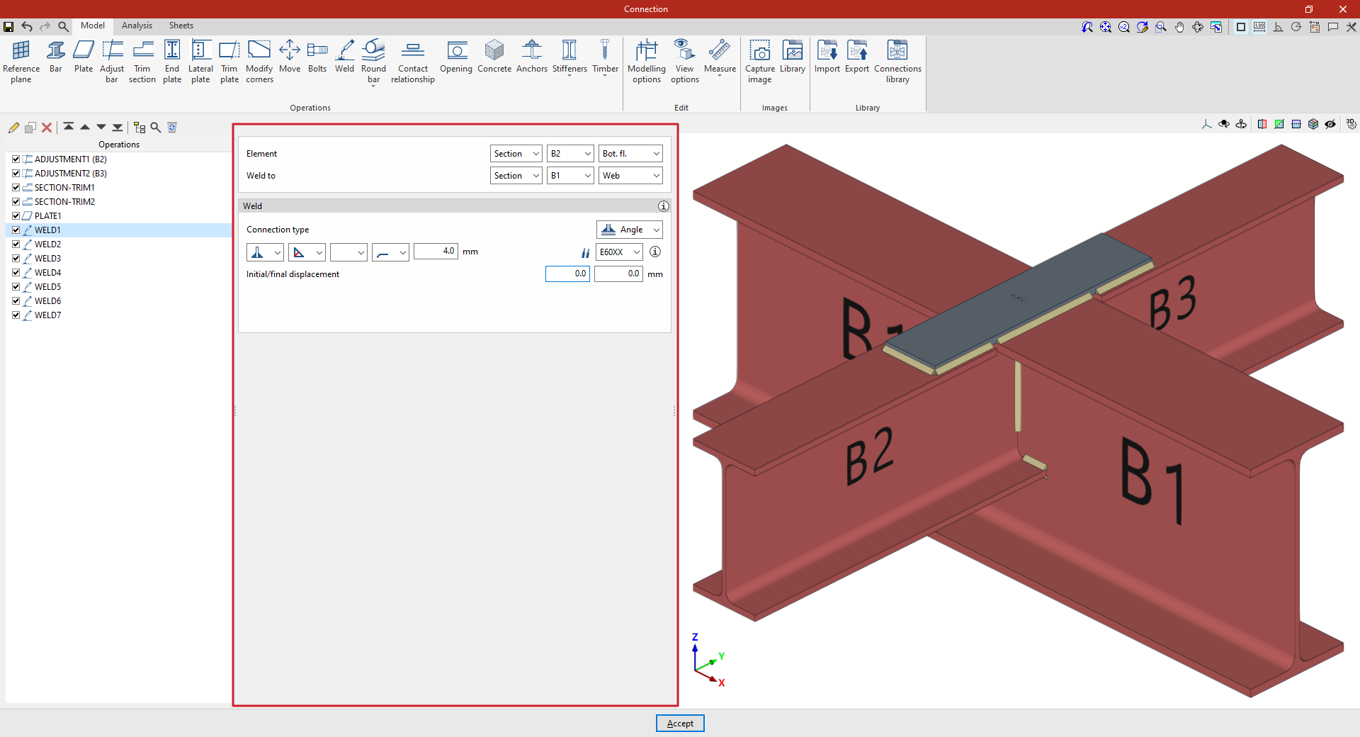
At the top of the central panel, select the “Element” to be welded from those available; this can be a “Section” or a “Plate”. If a section is selected, you must select the plate or part of the section to be welded, such as the upper flange (“Top flange”), the lower flange (“Bottom flange”) or the “Web” of rolled I sections.
Under “Connection type”, select whether the weld is a “Fillet weld” or a “Lap weld”.
The following welding parameters are defined below in the various drop-down menus:
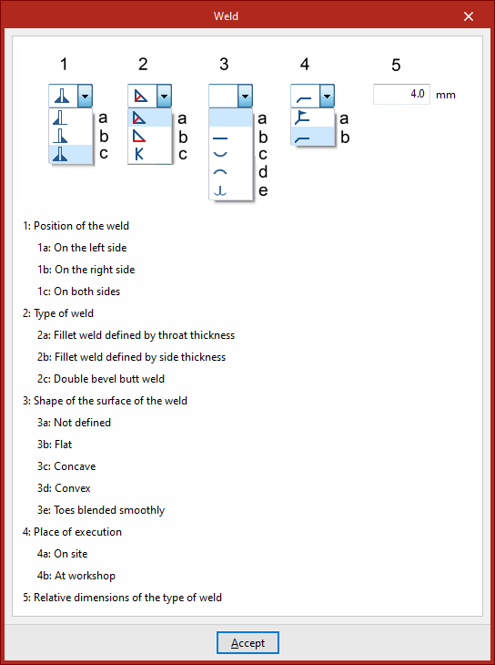
- The first drop-down menu shows various options for defining the position of the weld bead:
- On the left-hand side
- On the right-hand side
- Or on both sides
- In the second drop-down menu, select the type of weld from the available options, which are as follows:
- At an angle, defined by the throat thickness
- At an angle, defined by the side thickness
- Or flush-mounted with a double bevel
- The third drop-down menu allows you to define the shape of the weld surface, which can be undefined, flat, concave, convex or with smooth transition curves.
- The fourth drop-down menu specifies the location where the work will be carried out, either on-site or at a workshop.
The program provides a help section in the top-right corner, where you can find further information about these options.
On the right, you can select the “Electrode” from those available. The information button on the right allows you to view its parameters, such as its reference number or the resistance of the filler metal.
Finally, you specify whether the welds have an “Initial or final displacement”. By default, the program places the weld on the flat section of the wing, with the weld bead interrupted at the radius specified by the section.
In addition, for lap connections, the “Location” option appears, which can be set to “On all edges” or “On a given edge”. In the latter case, the“Edge number” must be specified; this can be found in the connection view.
Example
The example shown here demonstrates how to carry out welding operations to join beams.
| Note: |
|---|
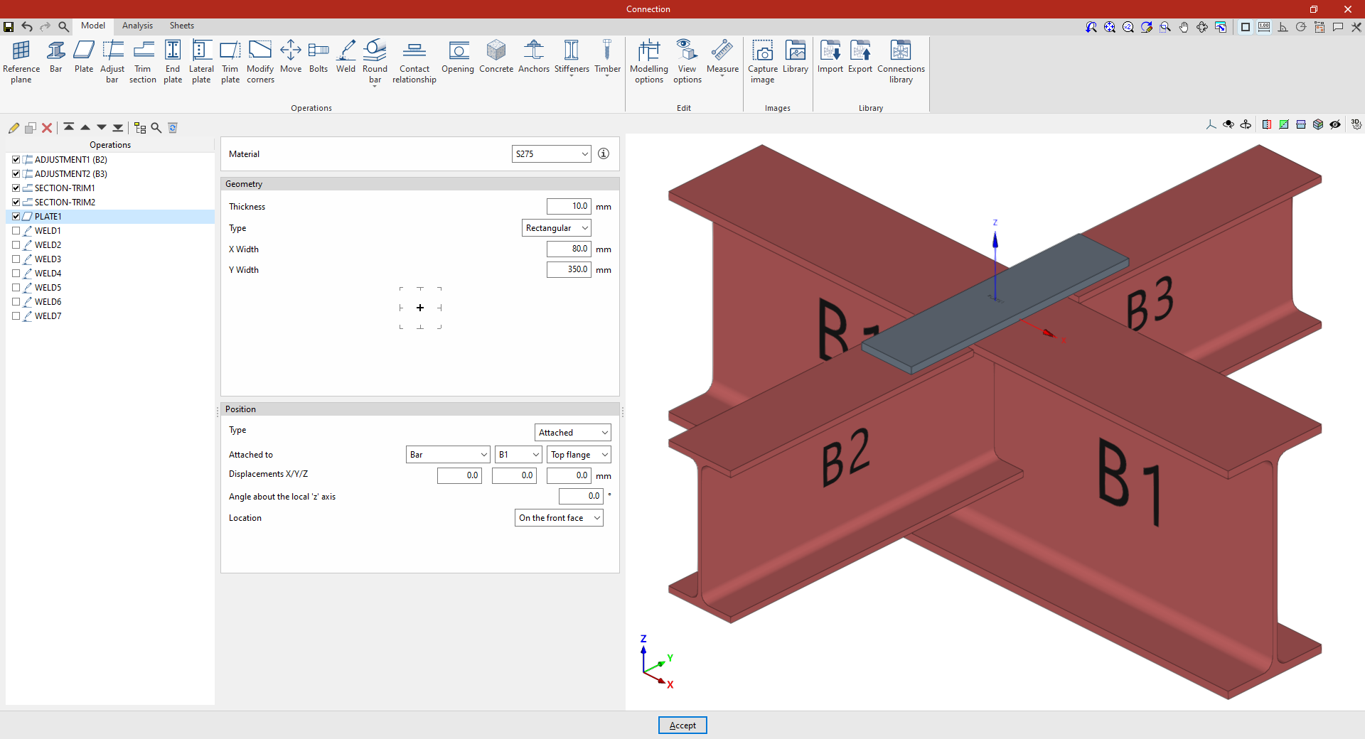
| In modelling this connection, adjustments and trimming have been made to the cross-sections of secondary beams B2 and B3, which connect perpendicularly to the main beam B1. In addition, a plate has been attached to the upper flange of beam B1. The necessary welds between the beam cross-sections and between the plate and the beams are then inserted. |
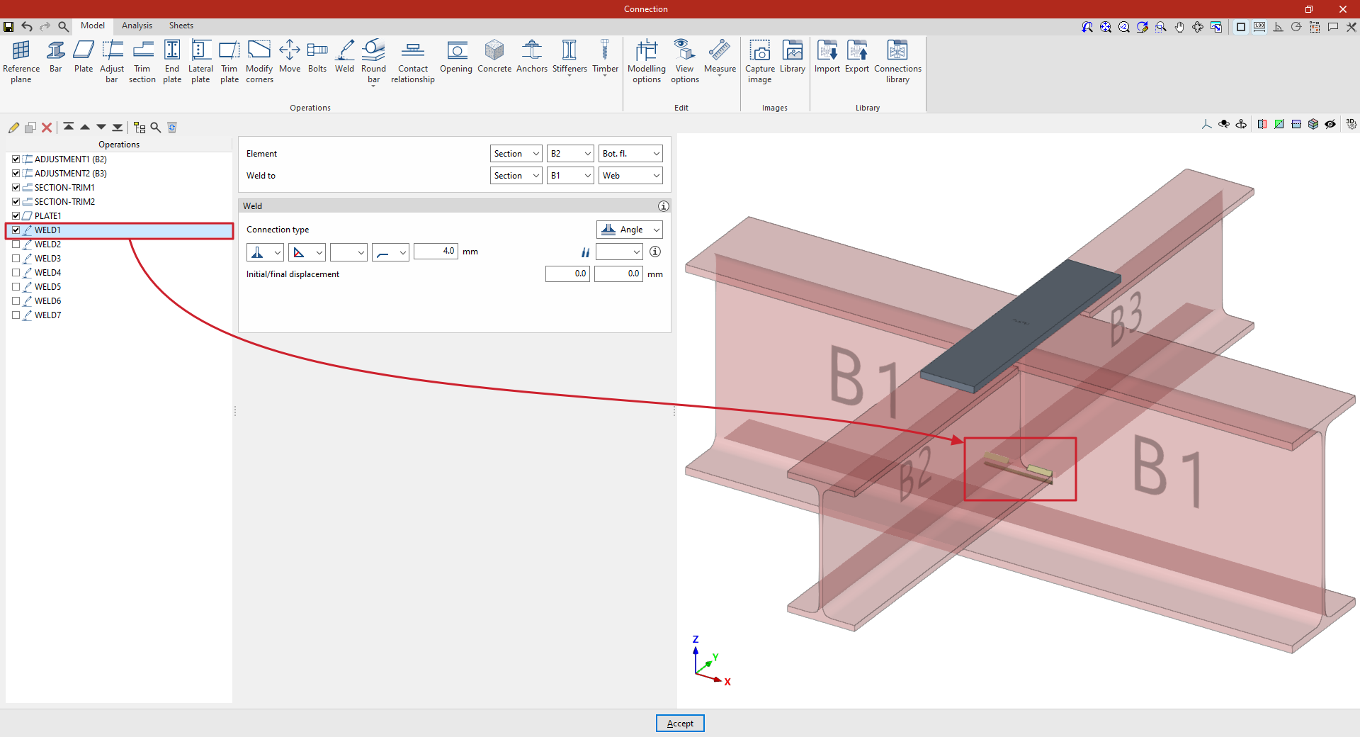
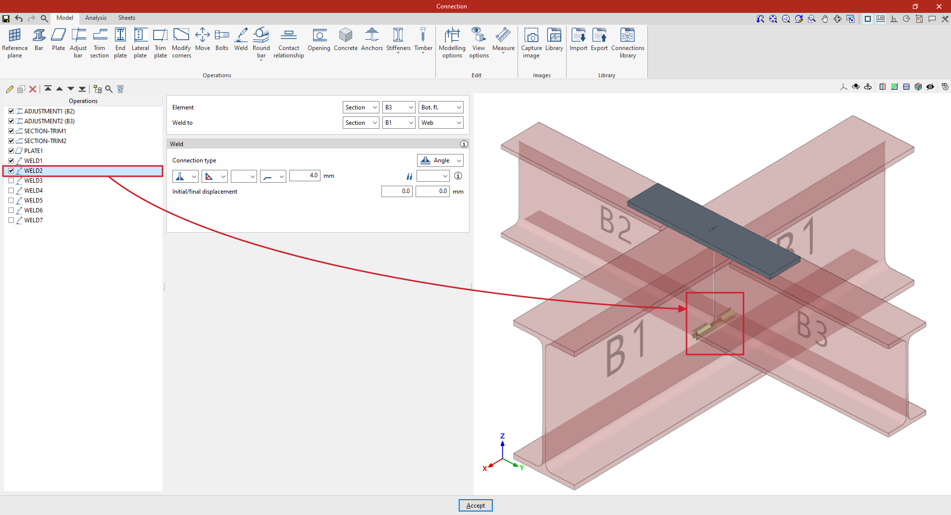
1. First, we describe how to add the welds for the lower flanges of a secondary beam to the web of the main beam. In this case, select “Section” and, from the drop-down menus on the right, select beam B2 and “Bottom flange”. Specify that you wish to “Weld to” another “Section”, corresponding to beam B1, and specifically to its “Web”.
Next, select “Angled” and, in the first drop-down menu, choose the option for both sides. Angled weld beads are defined by the groove depth, set to 4 millimetres.
2. To apply this operation to the other beam, after selecting the operation, use the “Copy” option at the top of the table on the left. In the new operation, under the “Element” section, select beam B3, leaving the other parameters unchanged.
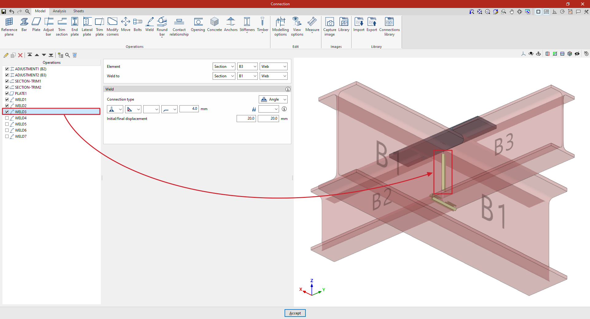
3. A new copy of the previous operation is created to apply it to “Section” B3, and specifically to its “Web”.
This defines the weld on the web of the secondary beam, which by default runs along its entire length. The length of the weld can be adjusted by entering an “Initial and final displacement” of 20 millimetres in both cases.
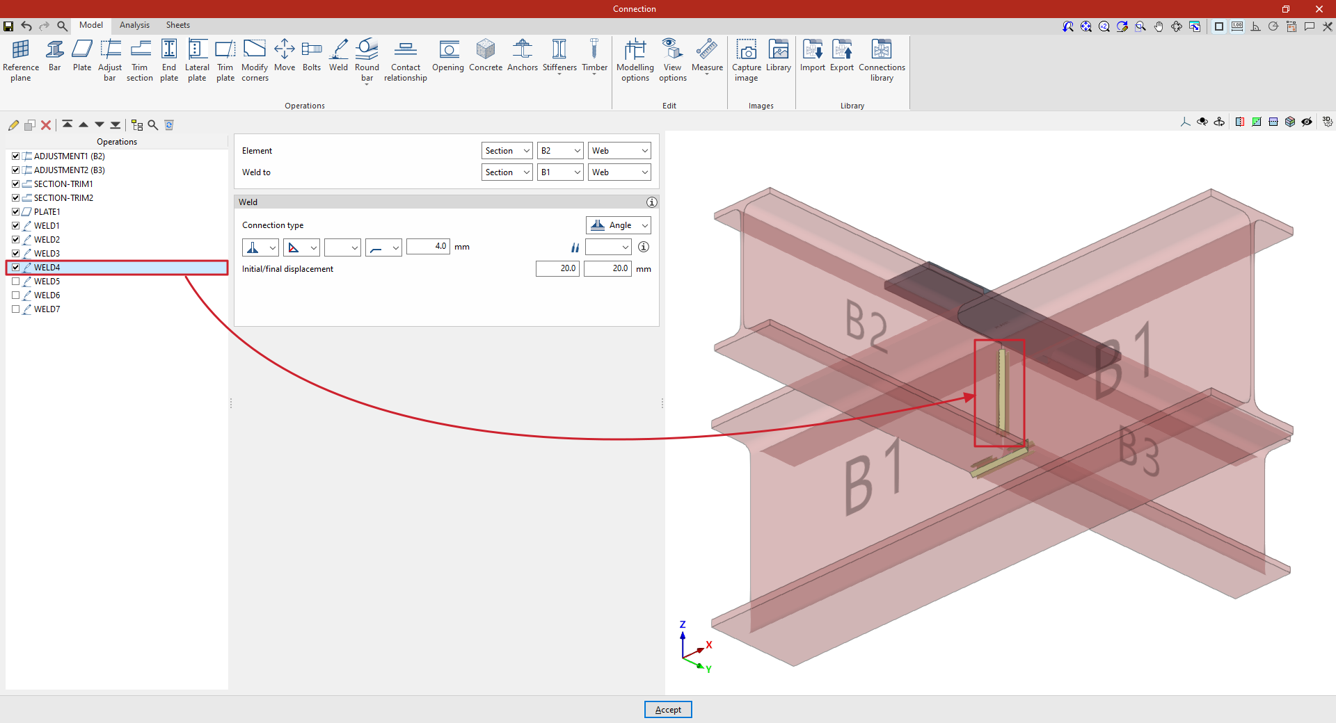
4. This procedure is repeated to apply it to the “Web” of “Section” B2, thereby completing the welds between the beam sections.
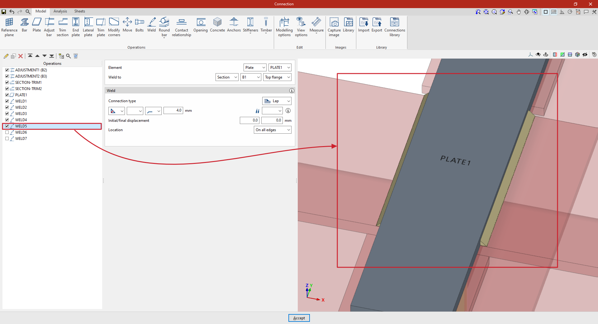
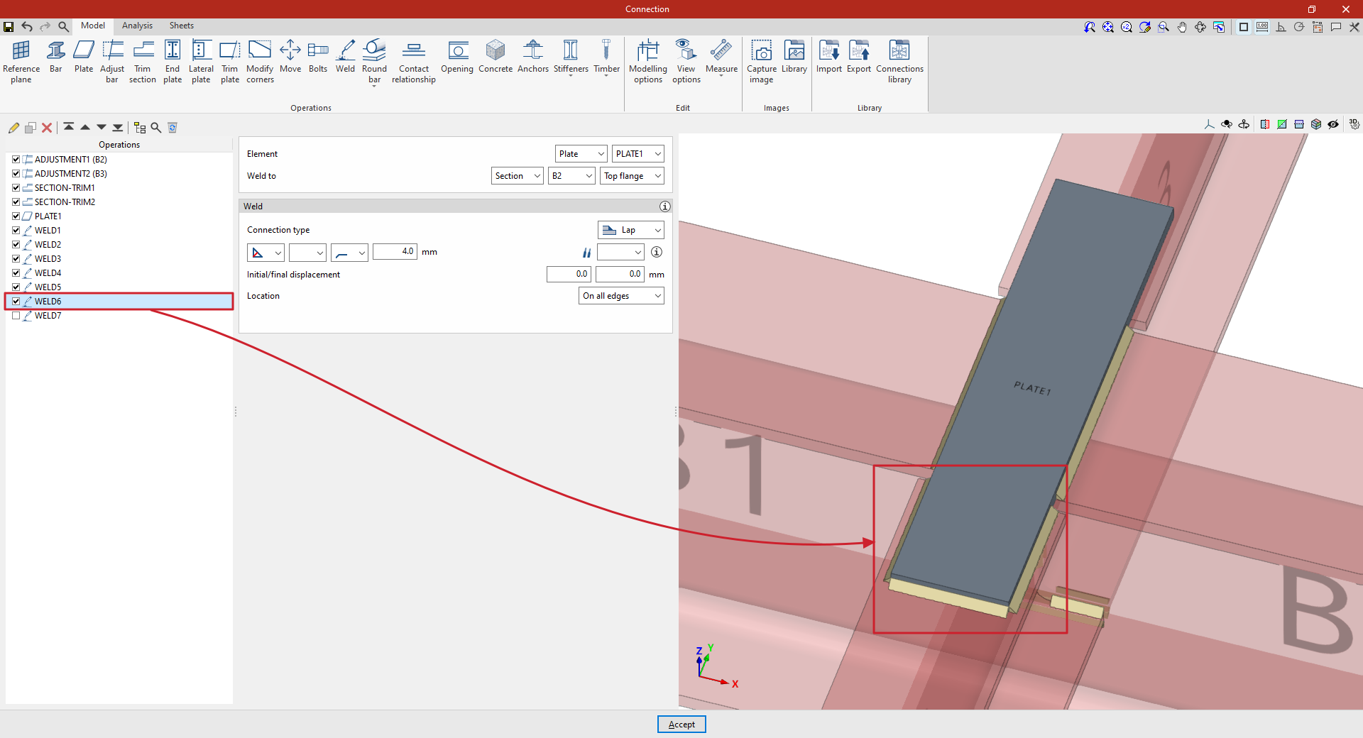
5. Next, define the welds between the plate and the beams. To do this, click on “Weld” again and, under “Element”, select “Plate”, choosing the single plate added to the model from the drop-down menu on the right.
Firstly, it is specified that you wish to “Weld to” “Section” B1, and specifically to the “Top flange”.
Within the “Welding” parameters, the “Connection type” is defined here as “Overlap”. Once again, an angled weld bead is defined by the groove depth, which is set to 4 millimetres.
“Alignment” is set to “All edges”.
6. To weld the plate to the secondary beams, copy the operation and apply the weld to section B2.
7. Finally, copy the operation again and select section B3, keeping the other parameters unchanged.
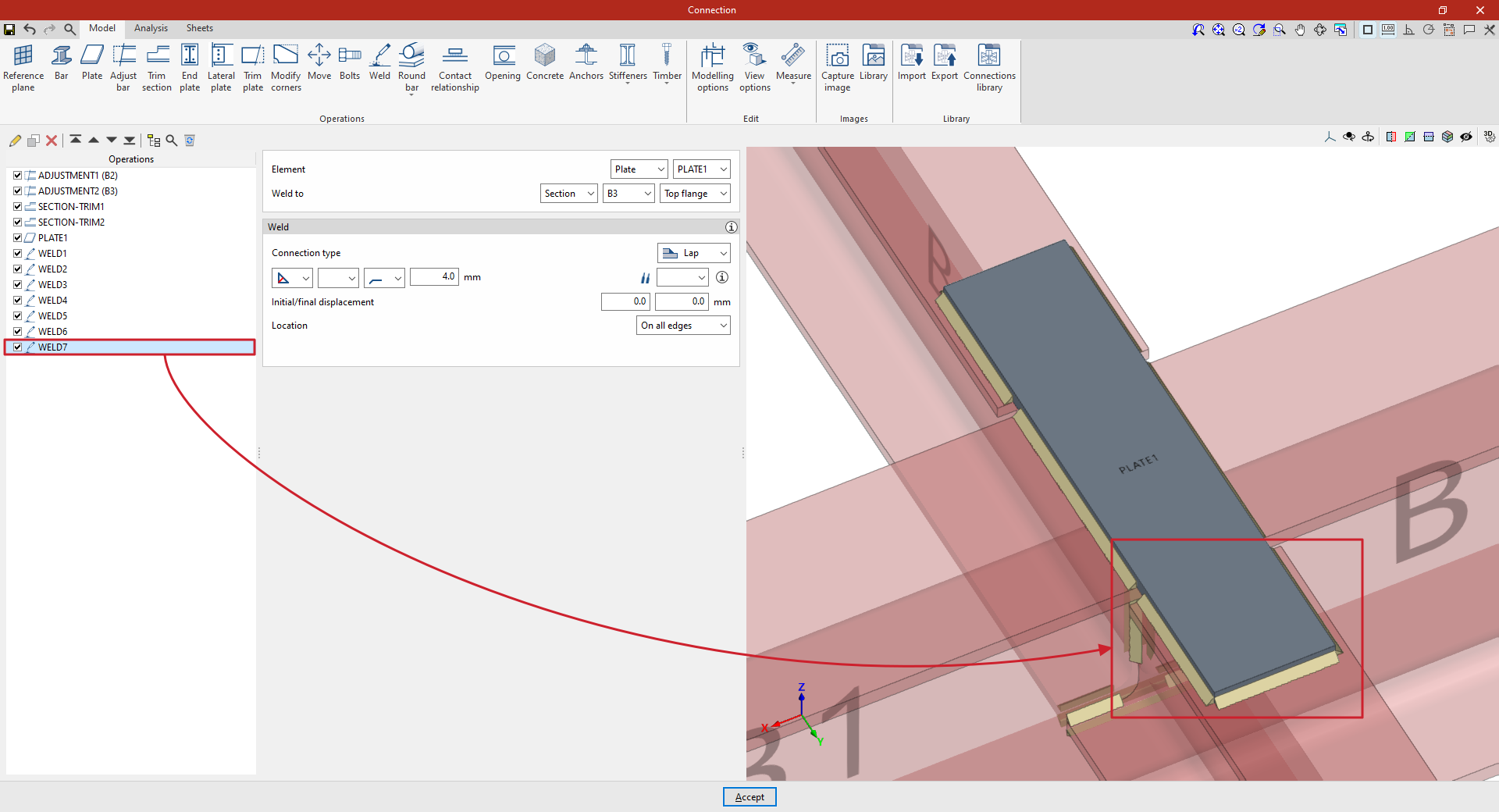
At this point, once the model is complete, you can continue by opening the “Analysis” tab to perform the analysis of the connection.