

"Bolts" function
The "Bolts" operation is used to insert bolts to join several bars or plates together.

Inserting bolts and selecting elements to be bolted
To add bolts to the connection, click on the “Bolts” option in the top toolbar.
At the top of the central panel, select the “Element” to be bolted from those available; this can be a “Section” or a “Plate”. If a section is selected, you must select the plate or part of the section to be bolted, such as the upper flange (“Top flange”), the bottom flange (“Bottom flange”) or the “Web” of rolled I sections.
Next, in the "Bolt to" drop-down menu, select the second element to be bolted to the first. Again, this can be a “Section” or a “Plate”; if you select a section, you must select the plate or part of the section where you want to place the bolt.
| Note: |
|---|
| If you wish to join more than two elements, simply select the two end elements of the connection. The program automatically detects whether there are any other elements between those selected in the drop-down menus, for example, a plate between two sections. |

Selecting and defining bolts
The following section defines the following parameters:
- You must specify the "Category" of the bolt as either "Not prestressed" or "Prestressed".
- Further down, the “Type” of bolt is defined by selecting its series and nominal diameter. If desired, you can click on the button on the right to open a window where you can view the part number and geometric properties of the “Bolt”, the “Nut” and the “Washer”, as well as the “Available lengths”. At the bottom, it indicates whether the bolt is “Prestressed” or “With lock nut”, as well as the “Number of washers on the side of the head” and the “Number of washers on the side of the nut”.
- The “Material” of the bolt is specified below. By clicking on the button on the right, you can view its specifications, including its “Reference”, “Description”, “Modulus of elasticity”, “Yield strength” and “Fracture limit”, as well as the material of the nut and washer.
- The drop-down menu below allows you to select the "Location", either "On site" or "At workshop".
- The "Reverse direction" box can be ticked to change the orientation of the bolts.
- Finally, the bolt's "drill bit" is specified. This can be:
- "Circular", in which case a "Space" is defined between the drill bit and the bolt,
- or "Elongated" in either of the two local directions (X or Y) of the sheet metal. In this case, the ratio between the length and the diameter of the hole ("L/d") is defined, with 1 being equivalent to a circle, as well as the "Space" between the hole and the bolt.
Bolt layout
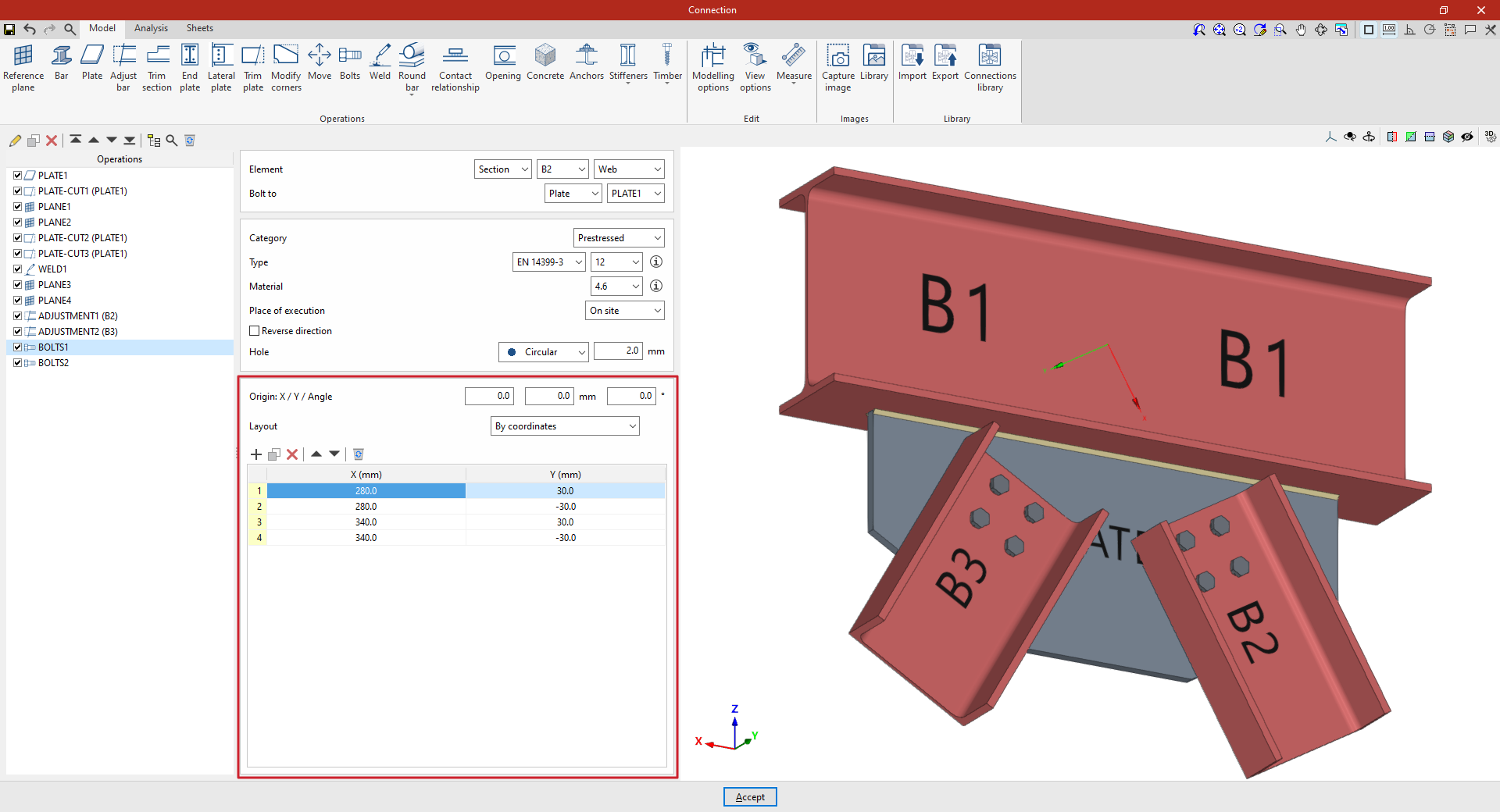
Next, in the following section, the bolts are positioned:
- You must define the local X and Y coordinates and the angle of the positioning origin for the bolts on the plate or bar by entering this data in the "Origin: X / Y / Angle" fields.
- Below, it is indicated whether the "Layout" of the bolts on the plate or bar is:
- "By coordinates",
- by "Rows and columns",
- by "Rows and columns per flange" (in front plates on double-T sections),
- "Perimeter" on the sheet metal,
- or "Radial".
| More information: |
|---|
| Further information on these layout options can be found via the following link. |
| Note: |
|---|
| The reference system for the bolt coordinates is the envelope of the selected element, i.e. its original geometry prior to any adjustments being applied. You can use the“Display options” to make the envelopes of the sections visible in the connection view. To do this, display the “Sections” in transparent mode by clicking on the cell in the “Drawing” column and activate the display of the “Envelope” in the right-hand panel. After clicking “Accept”, the section envelopes are displayed in grey. If this function is enabled, the program displays the coordinate origin of the bolts in the viewer, showing the X-axis in red and the Y-axis in green. |
Example
In this example, bolts are used to join a beam to two braces.
A welded plate has been added perpendicular to the lower flange of the beam, and trimming operations have been carried out to modify its geometry. In addition, the sections of the braces have been adjusted to avoid overlapping with the beam.
Next, insert the bolts between each of the diagonal braces and the plate:
- Step 1
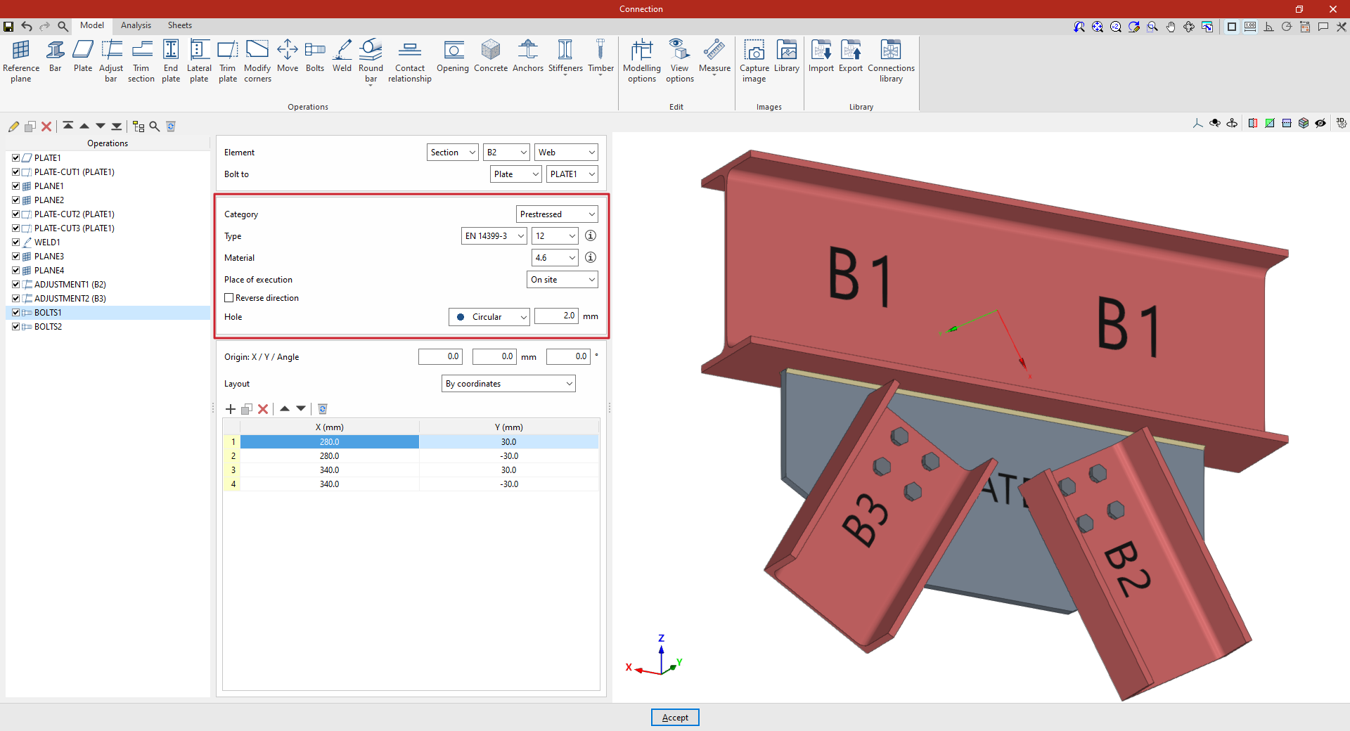
First, select “Section” B2, then select “Web”. Specify that you wish to “Bolt to” a “Plate”, selecting the only plate included in the model from the drop-down menu on the right.
Select the EN 14399-3 series and a nominal diameter of 12 from the drop-down menus. Select steel grade 4.6 and set a “Space” of 2 millimetres.
Next, manually define the position of the bolts by clicking “Add” to include them in the table and entering their “X” and “Y” coordinates in the units shown. In this case, four bolts are created manually with X and Y coordinates of 280 and 30; 280 and -30; 340 and 30; and 340 and -30 millimetres.
This adds the bolts connecting diagonal B2 to the welded plate.
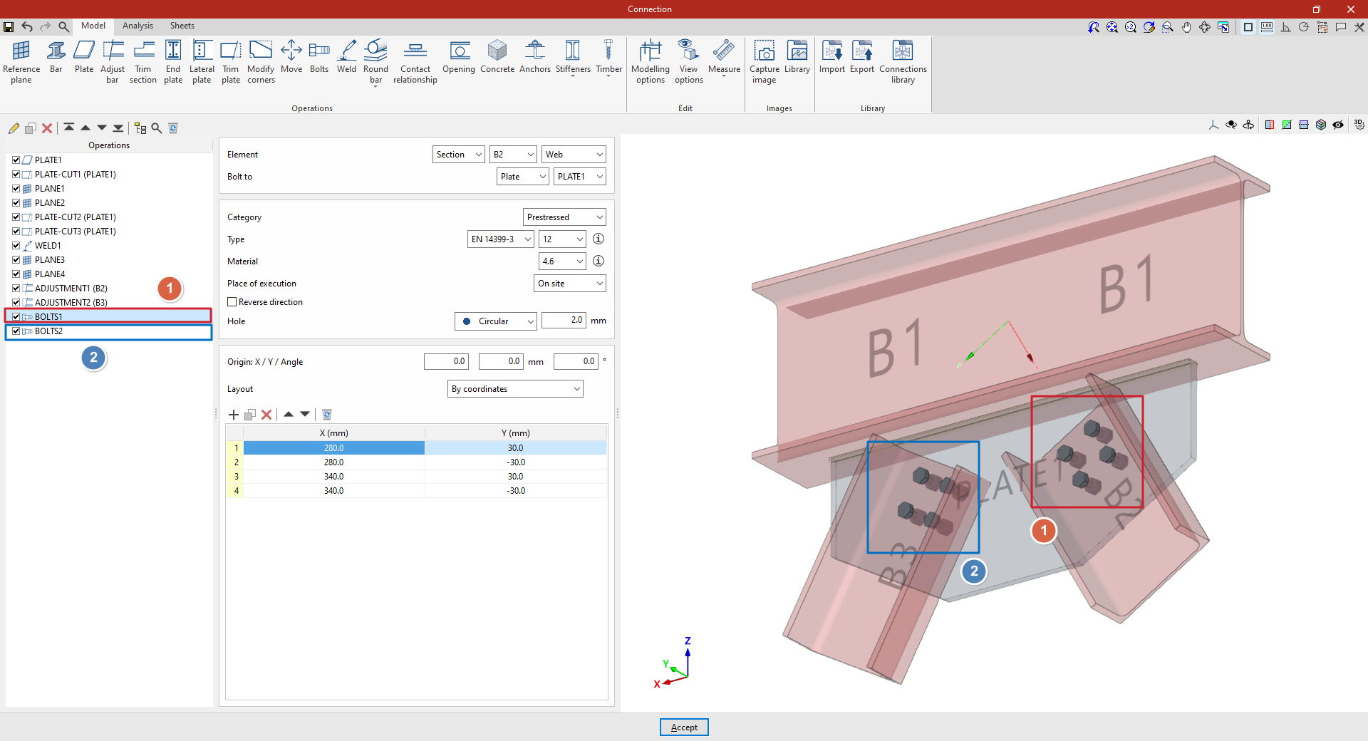
- Step 2:
To add the bolts connecting diagonal B3 to the same plate, select the step from the table on the left and click the "Copy" button at the top. Then, in the new step, change only the "Element" in the drop-down menu at the top to B3, leaving the other parameters unchanged.
At this point, once the model is complete, you can continue by opening the “Analysis” tab to carry out the analysis of the connection.