

"Opening" function
The "Opening" function allows you to create openings in sections or plates – whether circular, rectangular or polygonal – as well as to insert holes.

Inserting openings
To insert openings, click on the “Opening” option in the top toolbar.
First, select the “Element” where the opening is to be located, which can be a “Section” or a “Plate”. If a section is selected, you must select the plate or part of the section where you wish to create the opening, such as the top flange (“Top flange”), the bottom flange (“Bottom flange”) or the “Web” of rolled I sections.
The opening “Type” can be “Circular”, “Rectangular”, “Polygonal” or “Hole”:
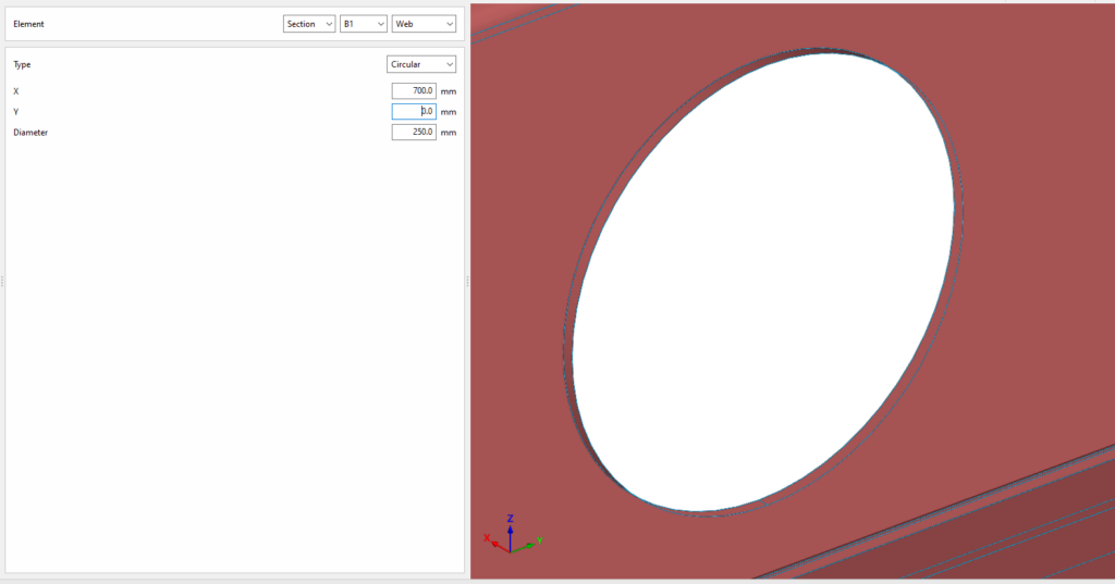
Circular openings
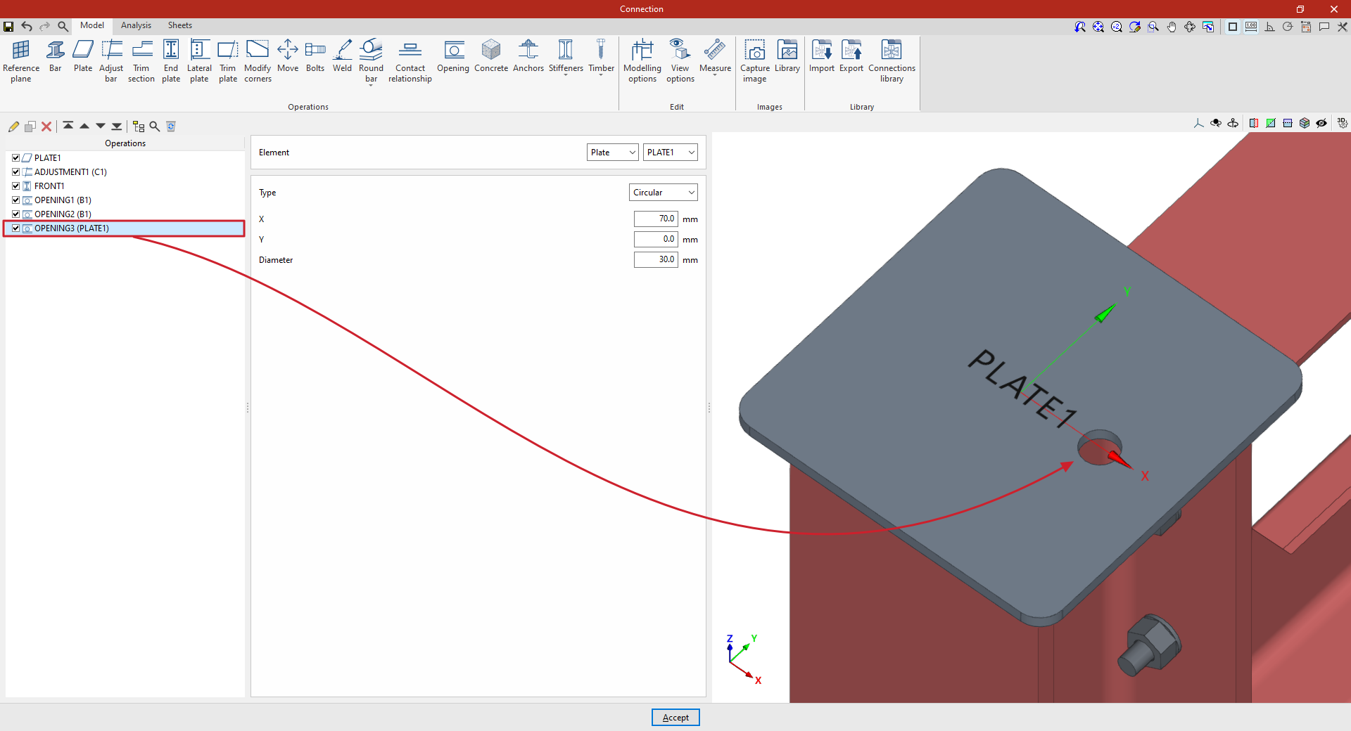
To insert circular openings, select “Circular” under “Type”.
To position a circular opening, enter the ‘X’ and ‘Y’ coordinates of the opening’s centre relative to the element’s local coordinate system. Finally, enter the "Diameter" of the opening.
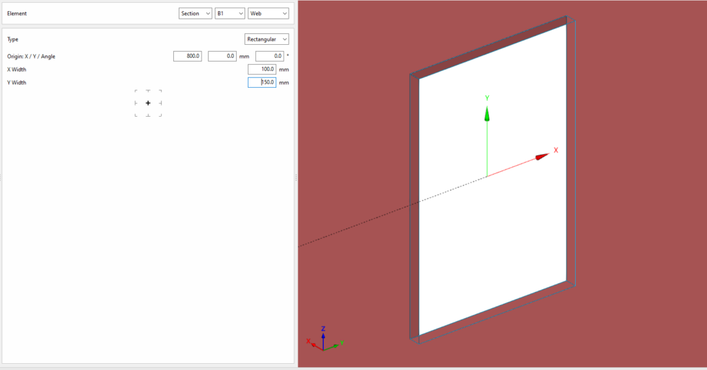
Rectangular openings
To insert rectangular openings, select “Rectangular” under “Type”.
You must define the local X and Y coordinates and the angle of the positioning origin for the openings in the element by entering this data in the "Origin: X / Y / Angle" fields.
Next, you must specify the “Width X” and “Width Y” of the opening.
In the diagram below, you can select the reference point for the opening: either its centre, the centre of one of its sides, or one of its corners.
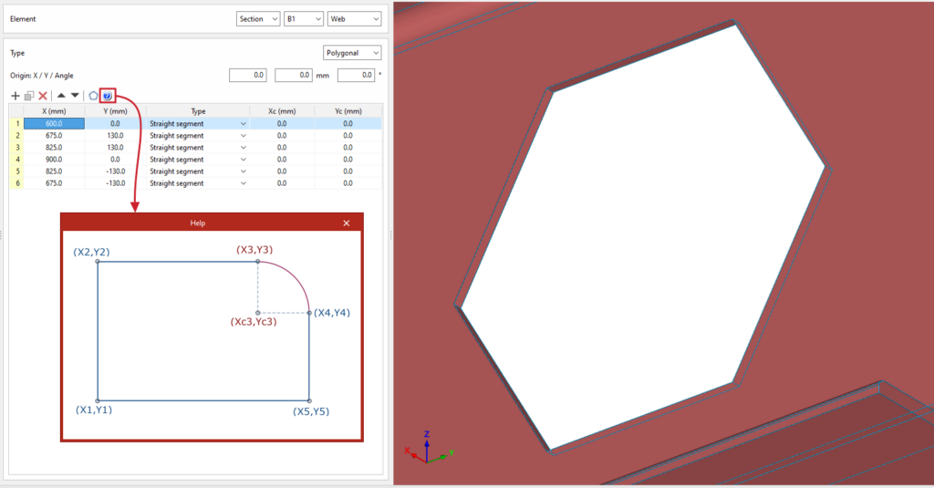
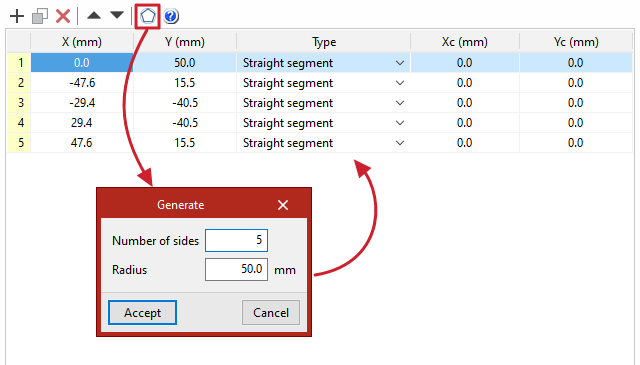
Polygonal openings
To insert circular openings, select “Polygonal” under “Type”.
For polygonal openings, a table appears in which the geometry of the opening is defined:
- The options on the top bar allow you to “Add”, “Copy”, “Delete” and reorder vertices in the list. You can click “Add” several times to enter the “X” and “Y” coordinates of the vertices that form the opening’s polygon.
- The polygon may include straight or curved sections:
- If it is a straight section, select "Straight segment" in the "Type" column and define the "X" and "Y" coordinates of the starting vertex. The section will extend to the "X" and "Y" coordinates of the next vertex.
- If the section is curved, select "Curved segment" in the "Type" column and define the coordinates of the centre of the arc, "Xc" and "Yc". The section will extend from the "X" and "Y" coordinates defined for it to the "X" and "Y" coordinates of the next vertex.
To make it easier to enter this data, the program displays a "Help" image when you click on the relevant button at the top of the table.
| Note: |
|---|
| Right-clicking on the cells in this table gives you access to additional features, such as "Paste from the clipboard", which allows you to enter data quickly if it has already been entered into a spreadsheet. |
The program also features a "Generate" tool at the top of the list, which allows you to automatically generate vertices for polygonal openings in straight segments by entering the "Number of sides" and the "Radius" of the circle circumscribed around the vertices of the opening. Using this tool will clear any data previously entered in the list.
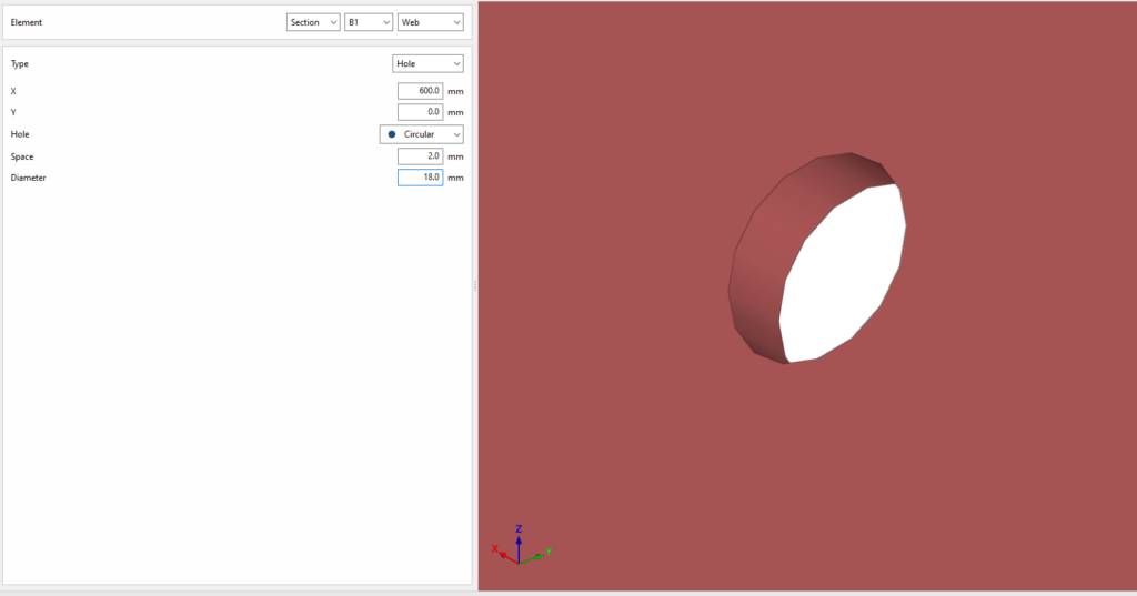
Hole
To add holes, select “Hole” under “Type”.
To position the hole, enter the "X" and "Y" coordinates of the hole centre relative to the part’s local coordinate system. Then select the type. This can be "Circular" or "Elongated":
- If it is "Circular", a "Space" is defined between the drill and the component passing through it, in addition to the "Diameter".
- The hole can be "Elongated" in either of the two local directions (X or Y) on the sheet metal. In this case, the ratio between the length and the diameter of the hole ("L/d") is defined, where 1 corresponds to a circle, as well as the "Space" between the hole and the through-part and its "Diameter".
Example
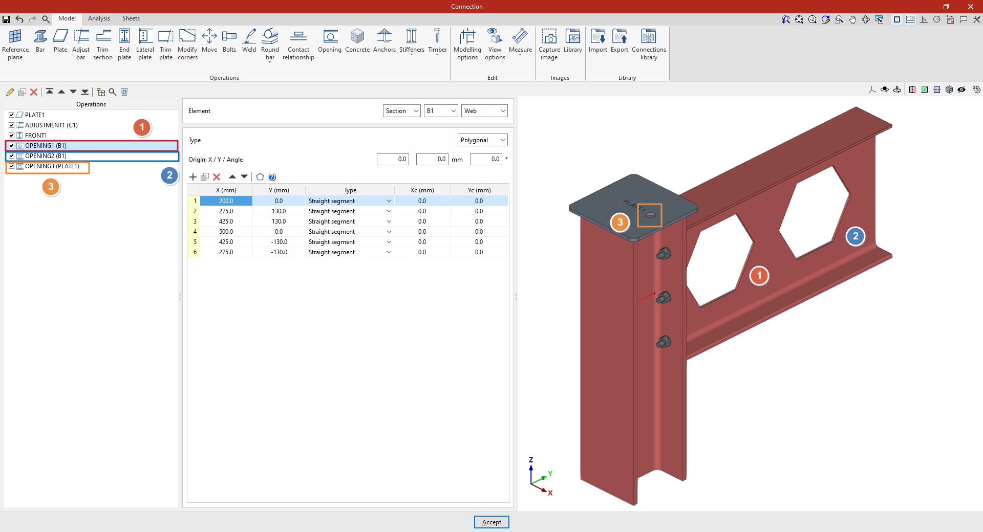
In this example, a plate has been inserted at the top of the column, and its geometry has subsequently been adjusted. A front plate has also been added to connect beam B1 and column C1.
Next, the necessary welds are made between the beam sections and between the plate and the beams.
Next, openings are cut into the beam to simulate a lightened web:
1. Select the “Section” B1 and choose the “Web”. In this case, the opening takes on a hexagonal shape, so select “Polygonal” and enter its coordinates in the table.
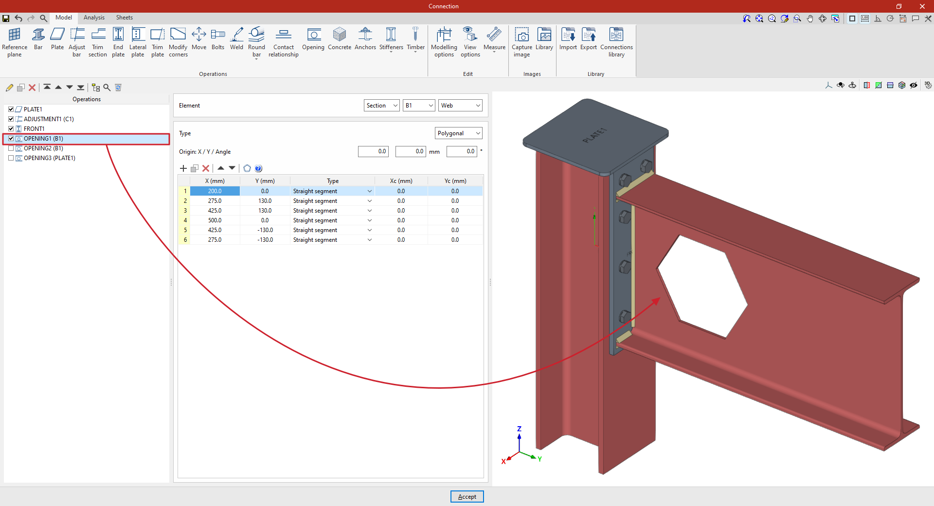
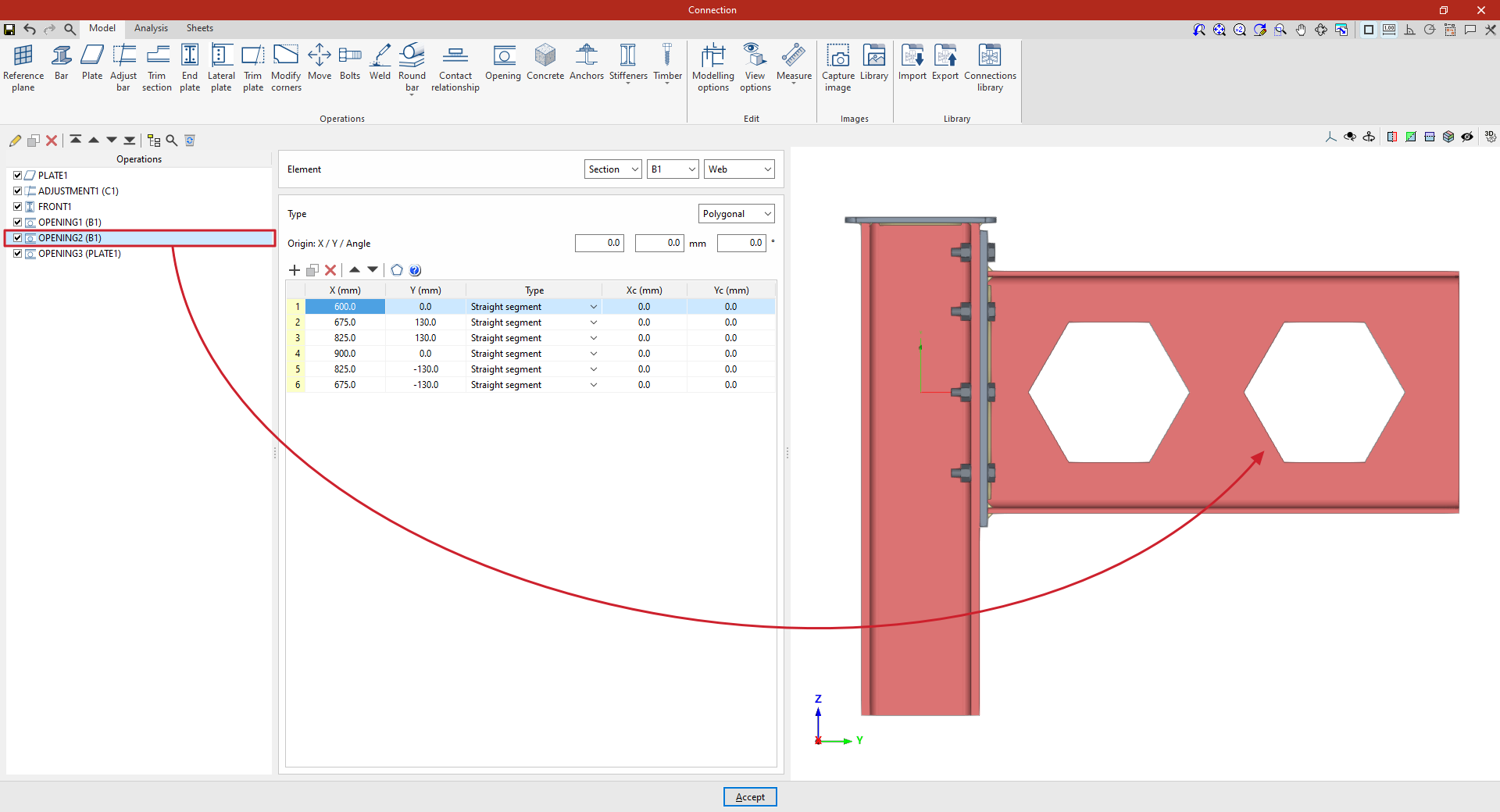
2. Further along, a second opening is cut into the beam.
To do this, copy the previous transaction by selecting it in the table on the left and clicking the “Copy” button at the top.
Next, whilst retaining the rest of the data, enter the coordinates of the new opening to position it correctly. The values can be typed directly into the cells or pasted from the clipboard.
3. To create an opening in the plate, click on the “Opening” option again and, in the “Element” section, select “Plate” 1 from the drop-down menu.
At this point, once the model is complete, you can continue by opening the “Analysis” tab to perform the analysis of the connection.