

"Adjust bar" function
The "Adjust bar" operation allows you to lengthen or shorten a bar by aligning it with another bar, a reference plane or a plate. It also allows you to generate welds after alignment.

Inserting bar adjustments and selecting elements
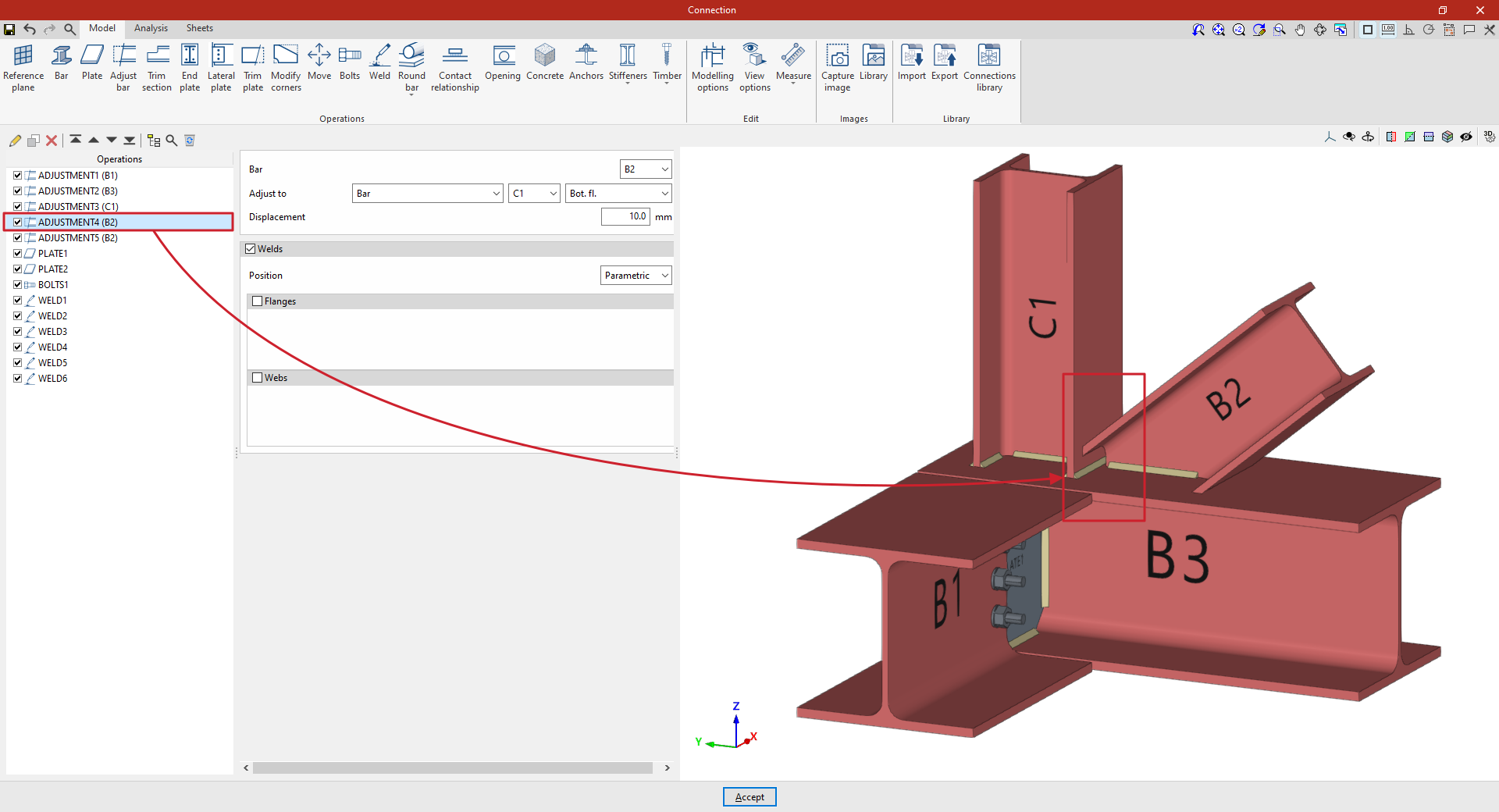
Clicking the “Adjust bar” option adds an adjustment operation. While the operation remains selected in the left-hand table, you can configure its parameters using the options in the central panel.
Use the drop-down menus at the top to select the “Beam” to be aligned. You can “Align to” a “Beam”, the envelope of a beam (“Beam (Envelope)”), a “Plate”, a “Reference plane” or a “Plane perpendicular to the beam”.
In the “Displacement” field, you can enter a value to adjust the position of the setting.
Using the adjustment tools, the section is lengthened or shortened to the specified point. The result of the operation is displayed in the viewport on the right.

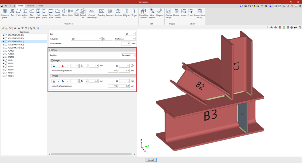
Defining welds in bar adjustments
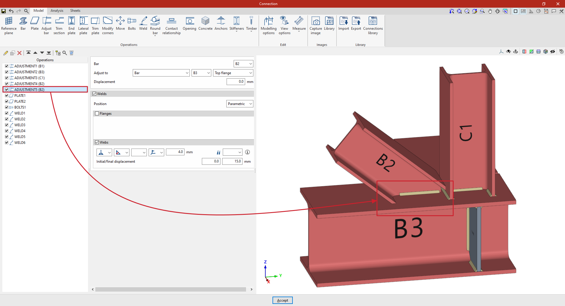
The program allows you to enter the “Welds” for the “Flanges” and “Webs” directly by ticking the relevant boxes. Within each section:
- The first drop-down menu shows various options for defining the position of the weld bead:
- On the left-hand side,
- On the right-hand side,
- Or on both sides.
- In the second drop-down menu, select the type of weld from the available options, which are as follows:
- At an angle, defined by the throat depth,
- At an angle, defined by the thickness of the weld side,
- Or flush-mounted with a double bevel.
- The third drop-down menu allows you to define the shape of the weld surface, which can be undefined, flat, concave, convex or with smooth transition curves.
- The fourth drop-down menu specifies the location where the work will be carried out, whether on-site or in the workshop.
On the right, you can select the “Electrode” from those available. The information button on the right allows you to view its parameters, such as its reference number or the resistance of the filler metal.
You must specify whether the welds have “Initial/final displacement” values. By default, the program places the weld on the flat part of the web, interrupting the weld bead at the radius specified by the section.
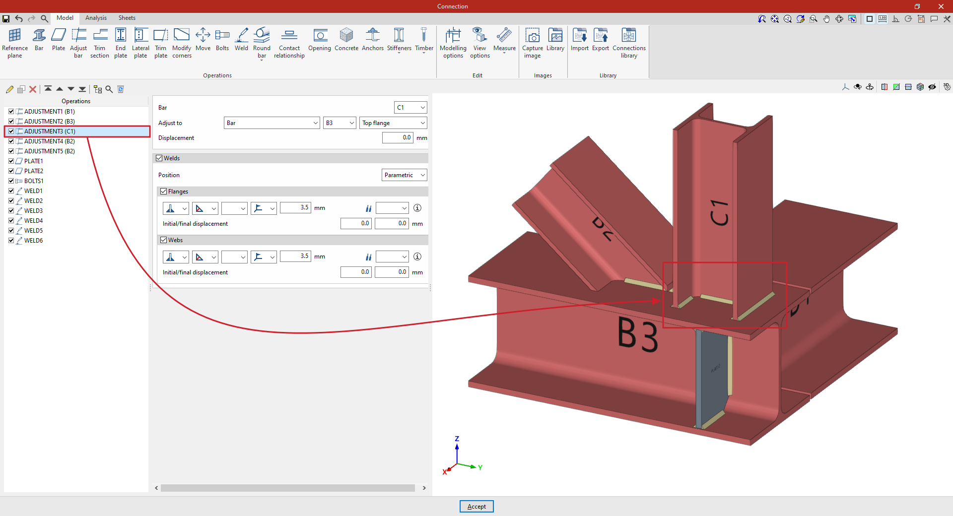
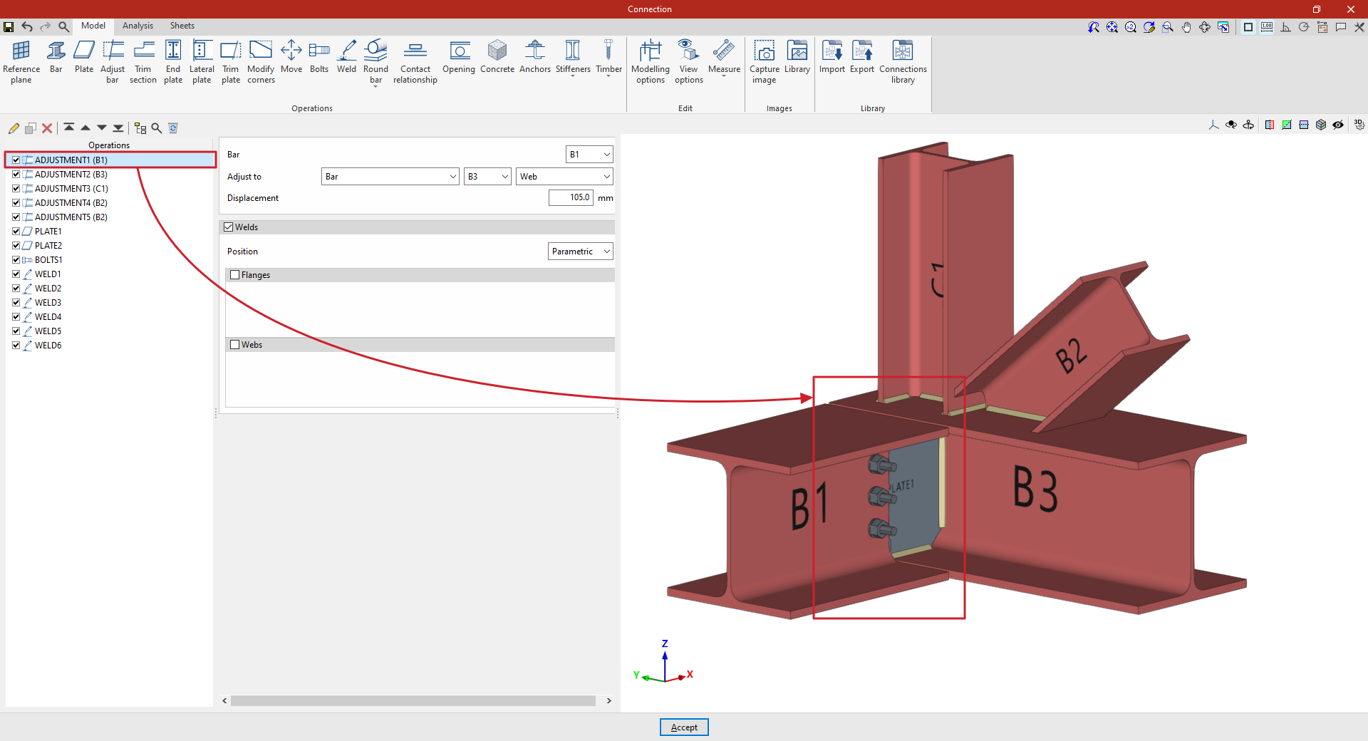
Example
In the example shown here, bar adjustment operations are entered to resolve a connection between four bars (C1, B1, B2 and B3):
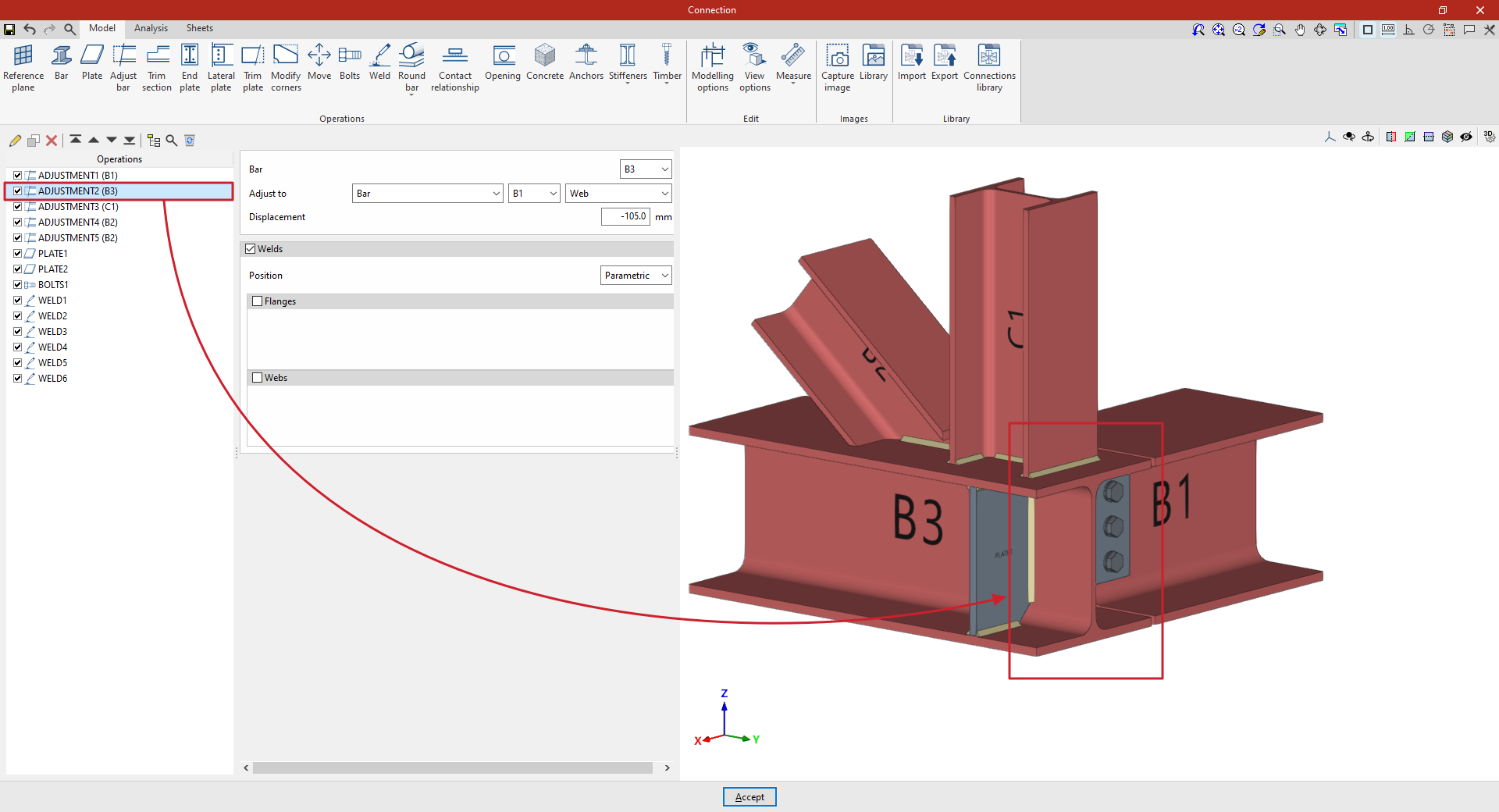
From this point onwards, the remaining operations required to complete the connection model must be added before the “Analysis” can be carried out.