"Modify corners" function
The "Modify corners" function allows you to edit the shape of the plates by adding cuts to their corners, such as a bevel, chamfer, notch, round or arc.

Overview of the corner modification operation
To perform this operation, click on the “Modify corners” option in the top toolbar.
To do this, after adding the operation, select the "Plate" you wish to edit from the drop-down menu. In the viewer on the right-hand side of the screen, the coordinates of each corner of the selected plate are displayed.
In the "Corners" table, you can define cut-outs at each corner. When you select each row in the table, the "Corner" number is displayed at the bottom; you then define the "Type" of cut and enter its dimensions.
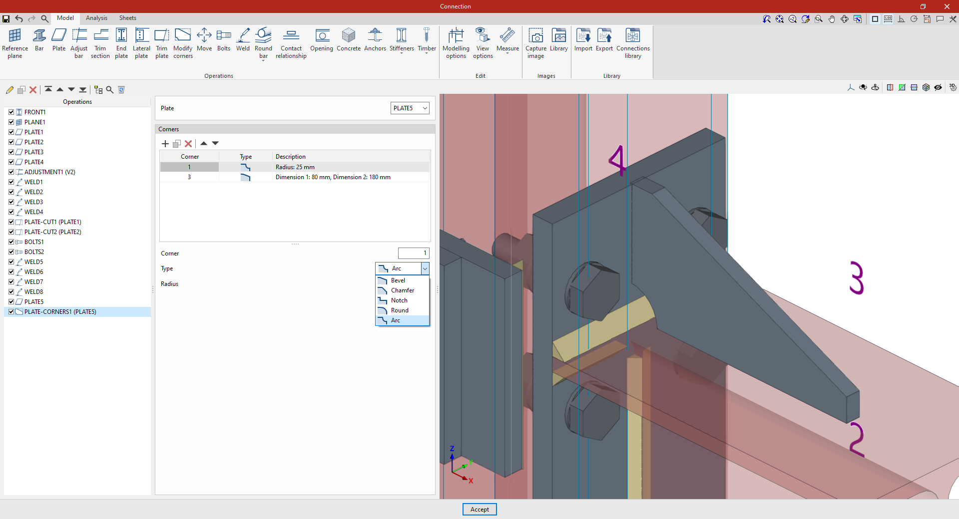
The types of cuts are as follows:
- Bevel
Trims the corner using a bevel. Define the "Dimension 1" and "Dimension 2" of the bevel. - Chamfer
Trims the corner using a symmetrical chamfer. The "Dimension" of the chamfer is defined. - Notch
Inserts a rectangular notch that may have a rounded inner corner. The "Dimension 1", "Dimension 2" and "Radius" of the notch are defined. - Round
Rounds the corner. You can set the "Radius" of the rounding. - Arc:
Trims the corner with an arc, creating a concave shape. The "Radius" of the arc is defined.
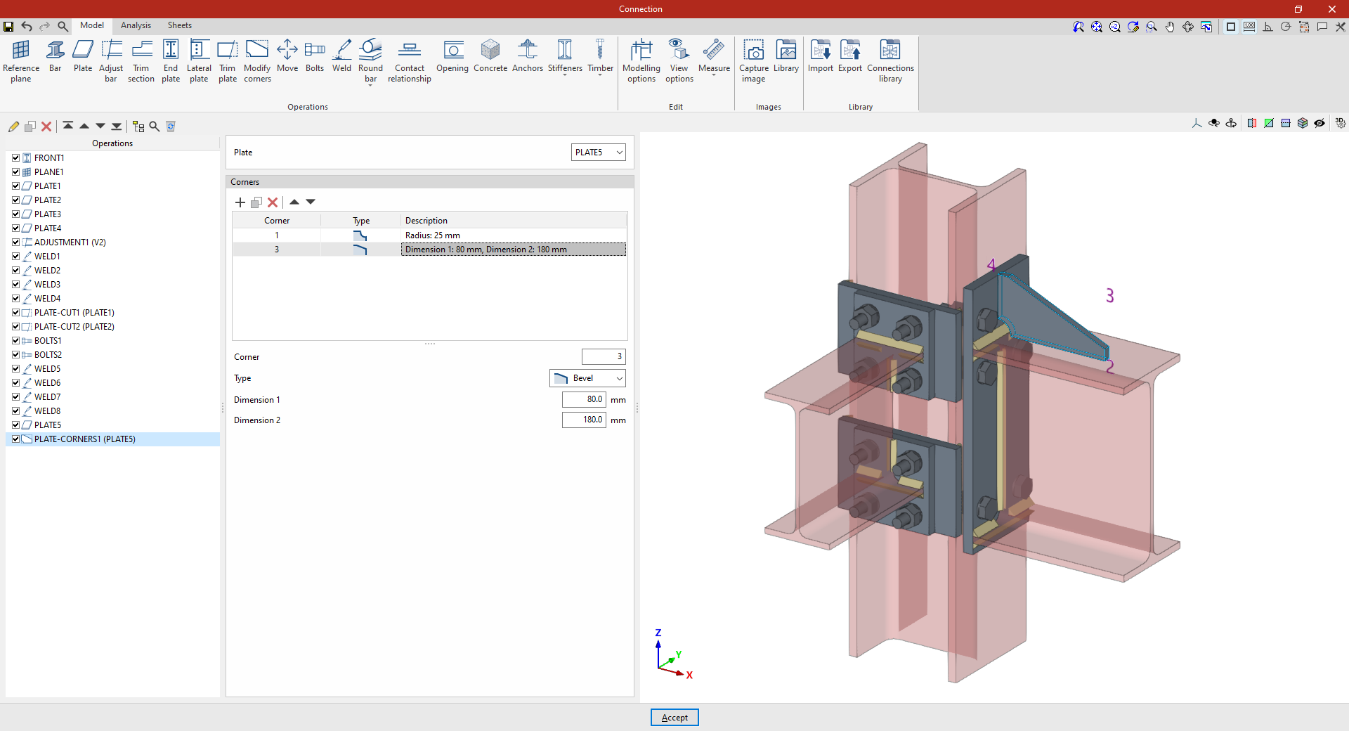
Example 1
In the first example, the aim is to modify the geometry of a plate perpendicular to a beam.
A new cut is added to corner ‘1’ in the "Corners" table. In this case, select a "Chamfer" cut and enter a "Dimension" of 25 mm.
Next, a new row is added to the table for “Corner” ‘3’, specifying a "Type" of cut as “Bevel”, with a “Dimension” of 80 mm in one direction and 180 mm in the other.
Thus, when this operation is applied to the selected sheet, it is transformed from a rectangular shape into the desired shape after the cuts are made at the corners.
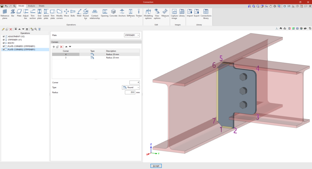
Example 2
In the second example, a stiffener has been defined that is bolted to the secondary beam, and cuts are to be applied to it.
Add the “Modify corners” operation and, in the “Plate” drop-down menu, select the stiffener.
In the “Corners” table, a cut is added to “Corner” ‘6’, of “Type” “Notch”, with dimensions of 20 mm and 105 mm, and a “Radius” of 10 mm.
A new line is added for the ‘5’ corner, with a notch measuring 105 mm by 70 mm and a radius of 10 mm.
As a result, the stiffener is now shown as a cut-out.
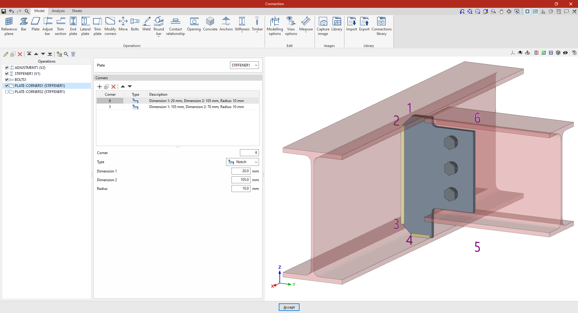
If a “Modify corners” operation is added again, the available corners are those resulting from the previous operations. For example, changes can be applied to corners ‘3’ and ‘4’. To do this, two new rows are added to the table for these “Corners”, selecting “Rounding” as the “Type” in both cases with a “Radius” of 20 mm.
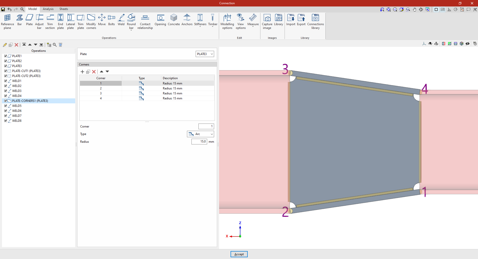
Example 3
In the third example, we want to make cuts at each of the corners of a slab situated between two beams.
Once again, select the “Modify corners” operation and choose “Plate” from the drop-down menu.
Next, add a fillet with a radius of 15 mm at corner ‘1’. Finally, you can create new fillets using the "Copy" option for corners ‘2’, ‘3’ and ‘4’.