"Reference plane" function
The "Reference plane" function allows you to insert auxiliary reference planes when modelling connections; these can be used to create cuts in sections and plates, to adjust the extension or reduction of these planes, or as a reference when adding plates.

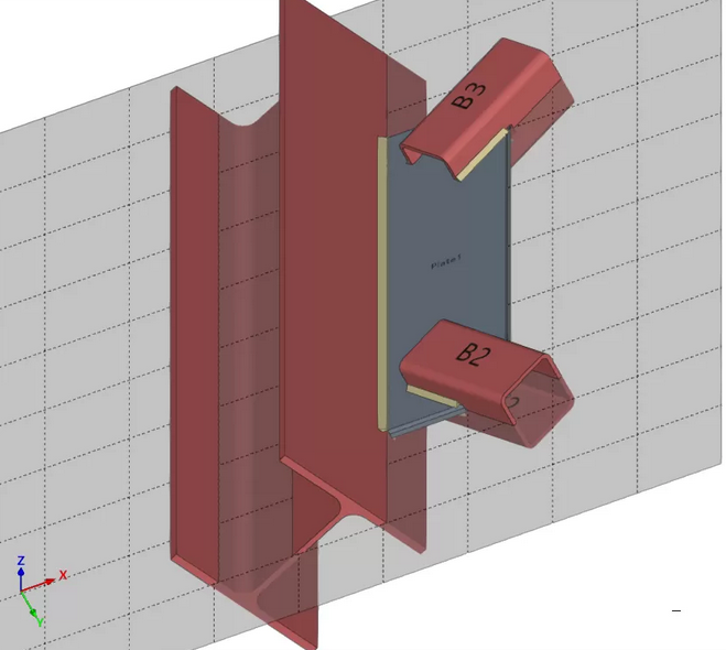
| Example (original situation): |
|---|
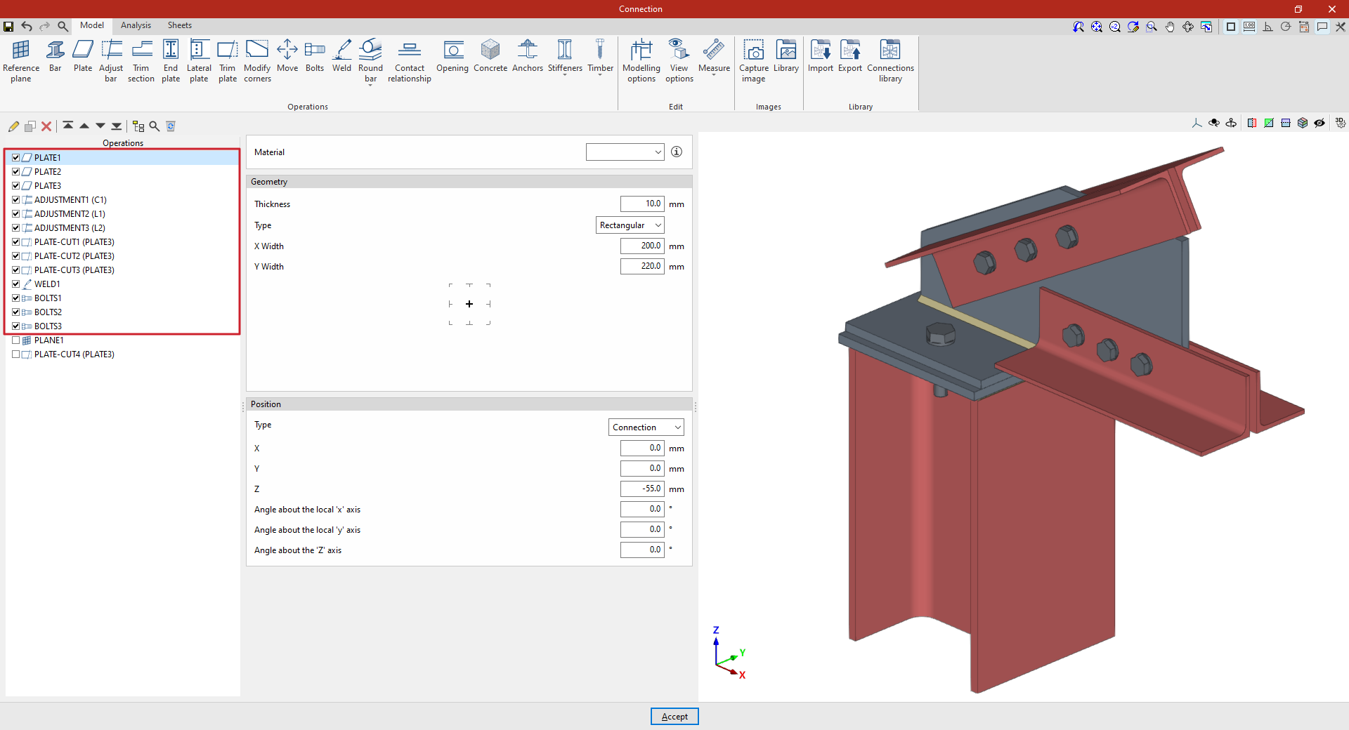
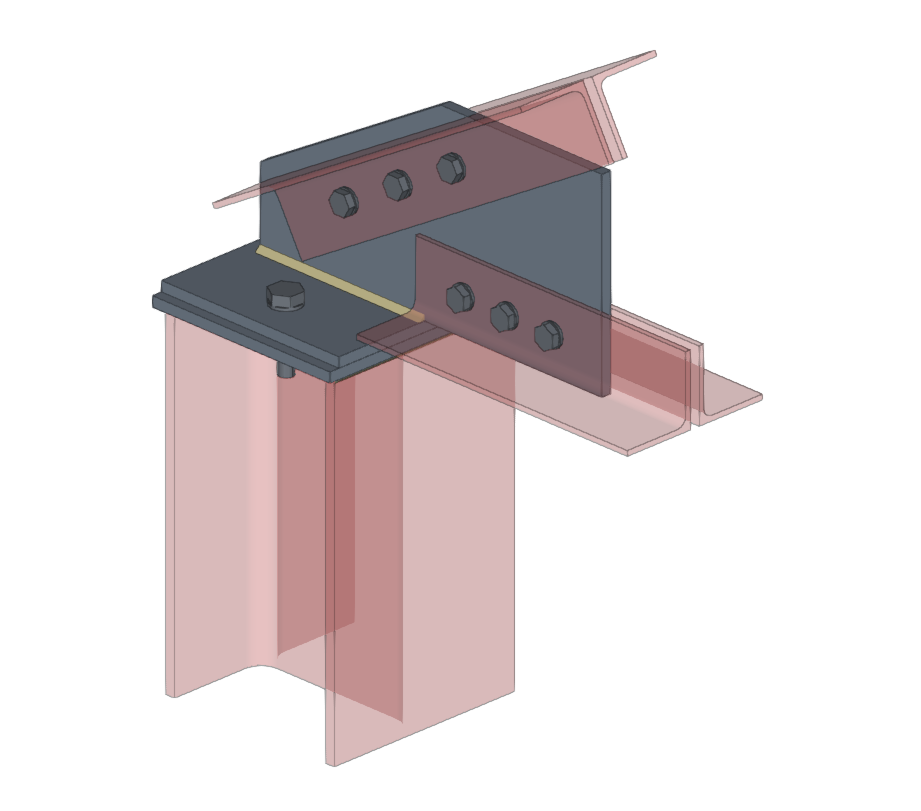
| In the example shown here, plates, bolts and welds have been added, and adjustments have been made to the connection sections and cut-outs in the plates. To complete the connection, a reference plane can be added, which can then be used to create the final cut-out on one of the plates in the model. |
Inserting the reference plane
To insert a reference plane, click on the “Reference plane” option in the top toolbar.
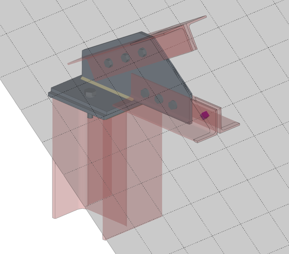
When you do this, the selected reference plane is displayed as a grey surface in the 3D view on the right.
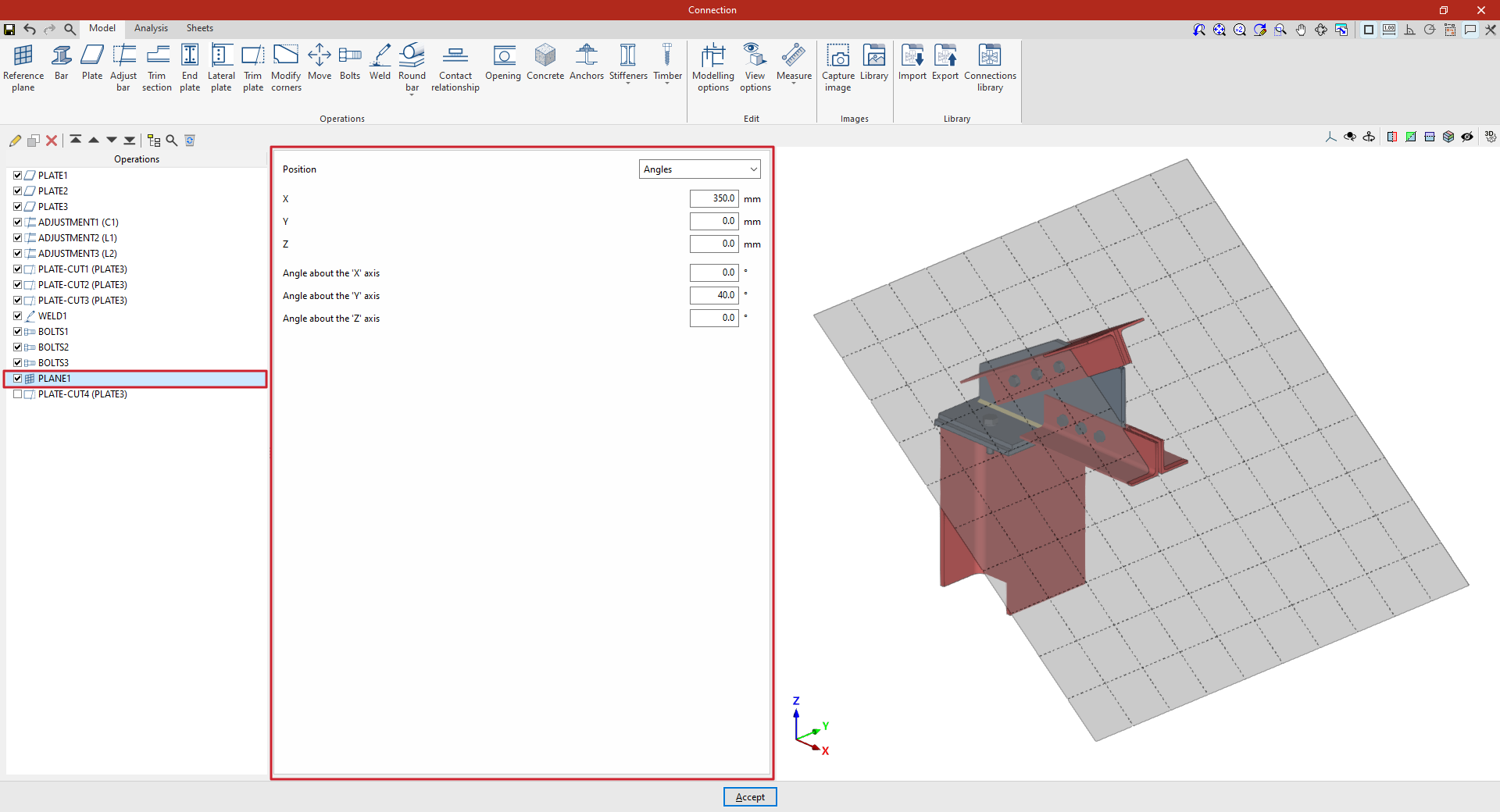
You can adjust the plane’s position using the options in the central panel. The “Position” can be set in the following ways, selected from the drop-down menu:
- By "Angles";
- Using a "Normal vector" to its surface;
- "Perpendicular" to a bar;
- "Defined by two bars" that make up the plane;
- On the "Bisector" between two bars;
- At the "Intersection" between two bars;
- At the intersection between a bar and the envelope of another (by selecting the "Intersection (Envelope)" option);
- Or perpendicular to the "Edge" of a plate.
| Example (continued): |
|---|
| Once the reference plane has been created, it can be used in other options such as “Trim section” and “Trim plate”, or to define the position of a “Slab” or a “Concrete” element. For example, you can define the “Position” using “Angles” and then add a slab trim that uses the “Reference plane” you have entered. This completes the connection model. From here, you can perform the “Analysis” of the connection in the tab provided for this purpose. |
Cutting a plate using a reference plane
The following options allow you to define planes in any position:
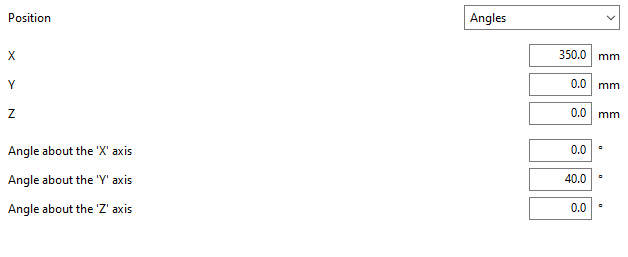
Angle-based reference plane
If “Position” is defined by “Angles”, you must first enter the “X”, “Y” and “Z” coordinates of a point on the plane.
The plane is then rotated by entering the “Angle about the ‘X’ axis” and the “Angle about the ‘Y’ axis”. These values refer to the global axes of the assembly’s coordinate system.
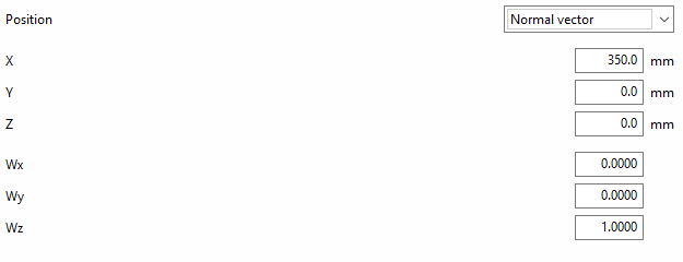
Reference plane using a normal vector
If the “Position” of the plane is defined by a“Normal vector” to its surface, the “X”, “Y” and “Z” coordinates of a point on the plane are specified first.
Next, the components “Wx”, “Wy” and “Wz” of the normal vector are written.
The following options allow the plane’s position to be referenced to other elements, meaning that if the dimensions or positions of the bars change, the plane’s position will also change. This is particularly useful when combined with the use of the connection library:
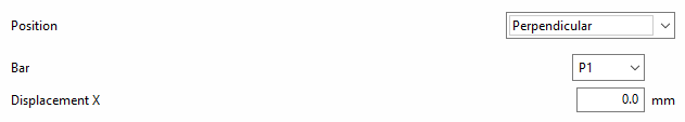
Reference plane perpendicular to a bar
To define the “Position”, you can specify that the reference plane is “Perpendicular” to a bar.
In this case, select “Bar” from the relevant drop-down menu.
You can then apply an “X displacement” to the plane along the section’s local X-axis; this can be either positive or negative.
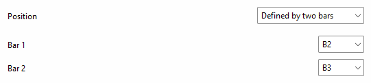
Reference plane based on two bars
To define the “Position”, it can be stated that the reference plane is established “Defined by two bars”.
In this case, select “Bar 1” and “Bar 2” from the relevant drop-down menus.
With this option, if the two selected bars lie in the same plane, the reference plane will be created at the point where their two local X-axes intersect. When the bars do not lie in the same plane, the reference plane will be created at the midpoint of their origins.
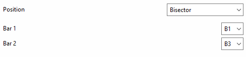
Reference plane on the bisector of two bars
To define the “Position”, one can state that the reference plane lies on the “Bisector” of two bars.
In this case, select “Bar 1” and “Bar 2” from the relevant drop-down menus.
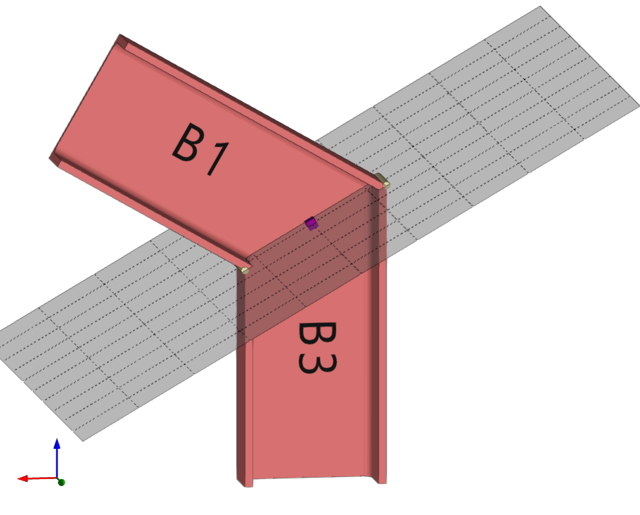
Reference plane at the intersection between a bar and one of the plates of another bar
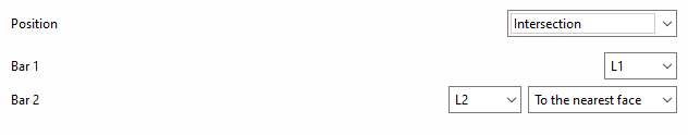
To define the “Position”, it can be stated that the reference plane lies at the “Intersection” between a bar and one of the plates of another bar.
In this case, select “Bar 1” and “Bar 2” from the relevant drop-down menus.
You must specify the plate or part of the second bar with which you wish to obtain the intersection, for example, "To the nearest face", "To the furthest face", the "Flange" or the "Web" of an L-shaped section.
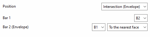
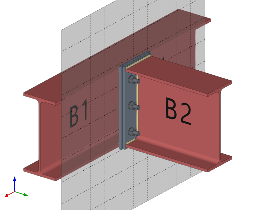
Reference plane at the intersection of one bar and the envelope of another bar
To define the “Position”, you can specify that the reference plane lies at the intersection of one bar and the envelope of another bar (using the “Intersection (Envelope)” option).
In this case, select “Bar 1” from the first drop-down menu and the bar for which you wish to analyse the envelope from the second drop-down menu (“Bar 2 (Envelope)”).
You must specify the face of the envelope with which you wish to obtain the intersection, whether it be "To the nearest face", "To the furthest face", the top face ("Top face"), the bottom face ("Bottom face"), the left face ("Left face") or the right face ("Right face").
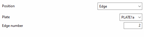
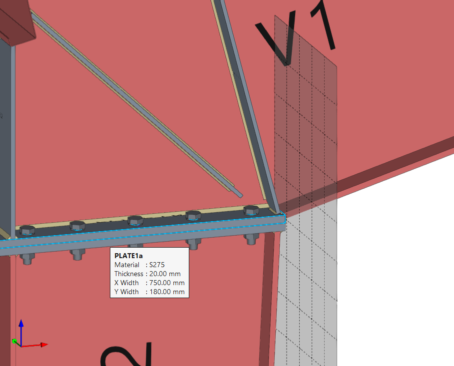
Reference plane at the edge of a plate
To define the “Position”, one can specify that the reference plane lies on the “Edge” of a plate.
In this case, select “Plate” from the first drop-down menu, and enter the “Edge number” of the plate where you wish to place the drawing in the corresponding field.