

"Plate" function
The "Plate" tool allows you to create rectangular and polygonal plates and insert them into the connection model. Polygonal plates can be defined using coordinates, and you can copy and paste tables directly from spreadsheets.

Inserting the plate
To insert a plate, click on the “Plate” option in the top toolbar.
| Note: |
|---|
| In the example shown here, adjustment operations have already been carried out on the sections to modify their geometry. Next, three plates are added to complete the connection between the sections. |
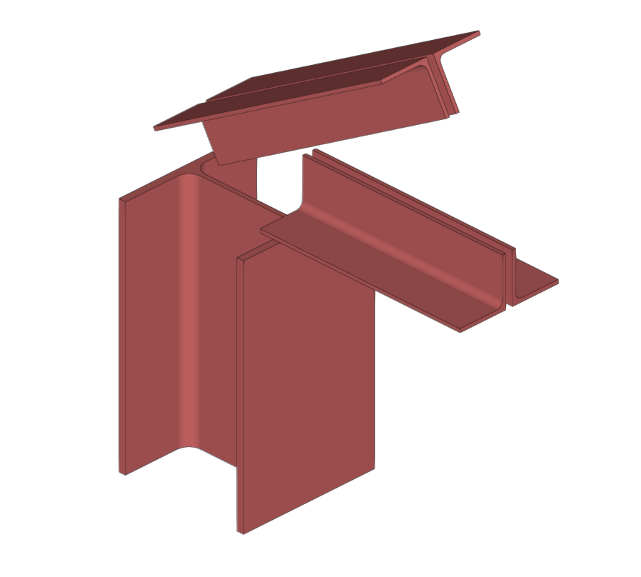
Inserting plates to resolve the intersection between different sections
Selecting plate material
First, select the “Material” for the plate from the drop-down menu. If you click on the information button on the right, you can view its properties.

Defining the plate geometry
The following section defines the “Geometry” of the plate. Enter the “Thickness” and select the “Type” of plate from the drop-down menu: “Rectangular”, “Circular” or “Polygonal”.
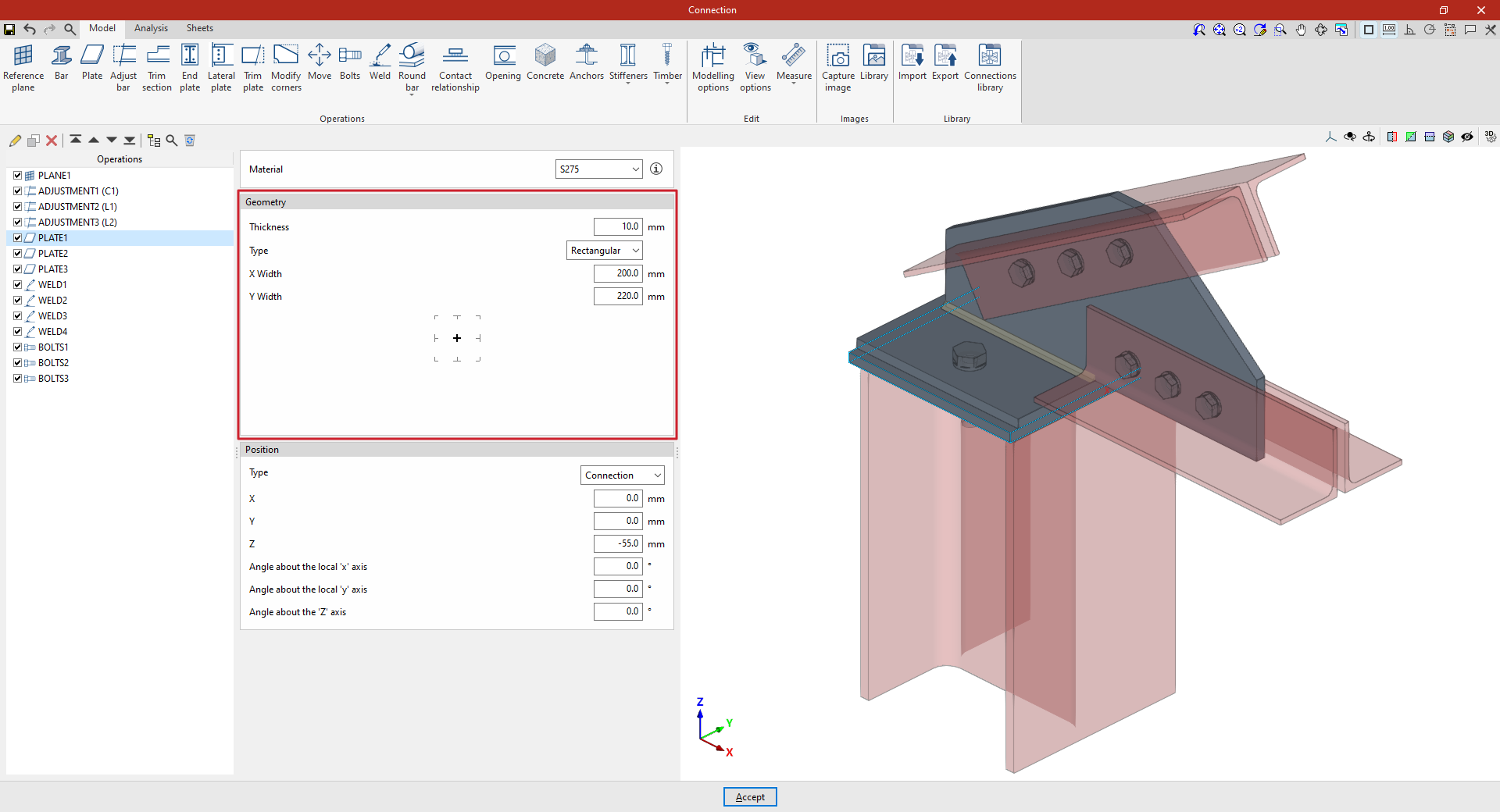
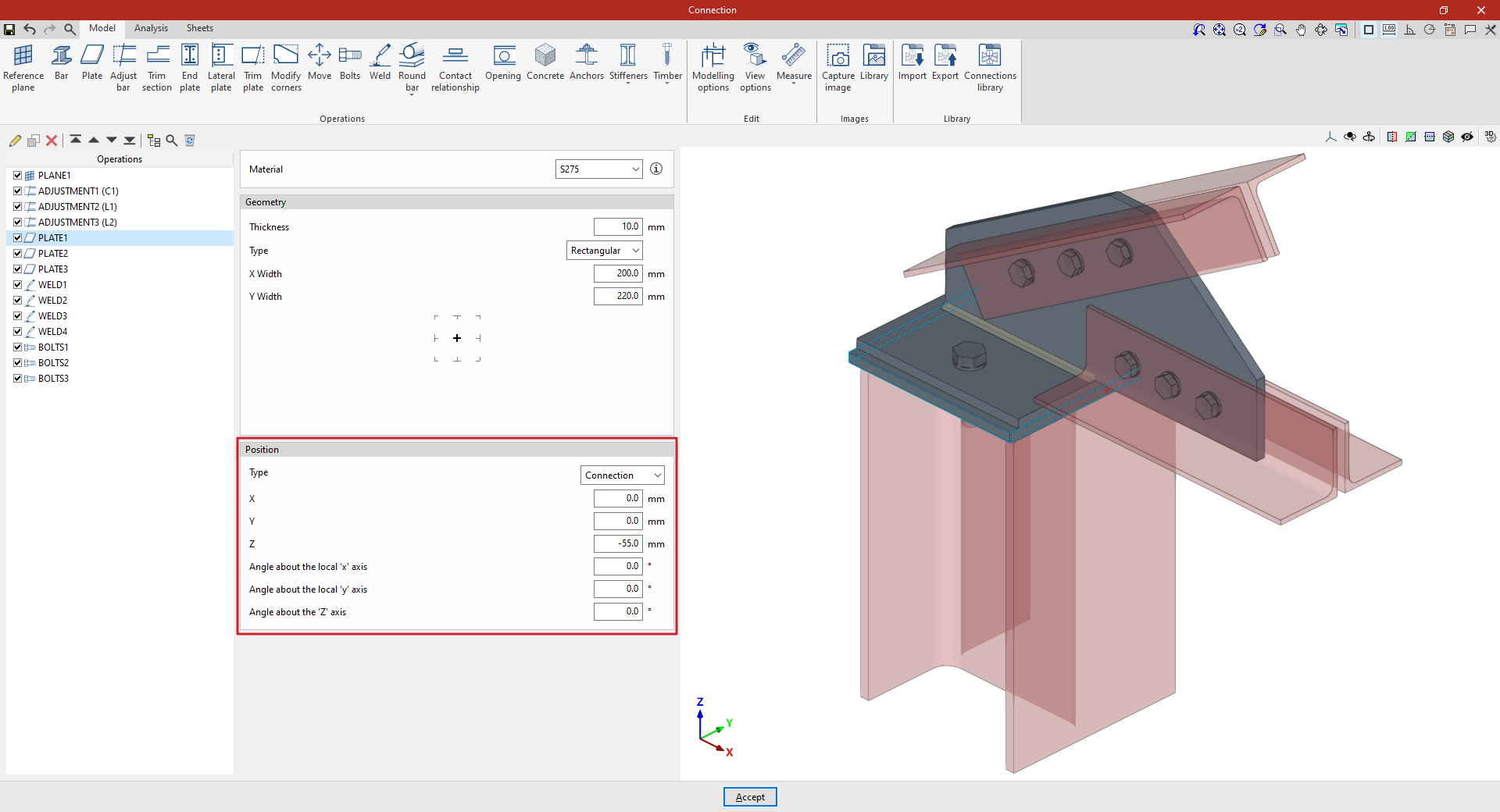
Rectangular plates
If “Rectangular” is selected, you must specify the “Width X” and “Width Y”.
Circular plates
If you select “Circular”, simply enter its “Diameter”.
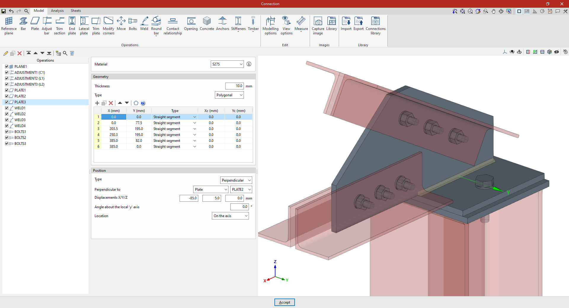
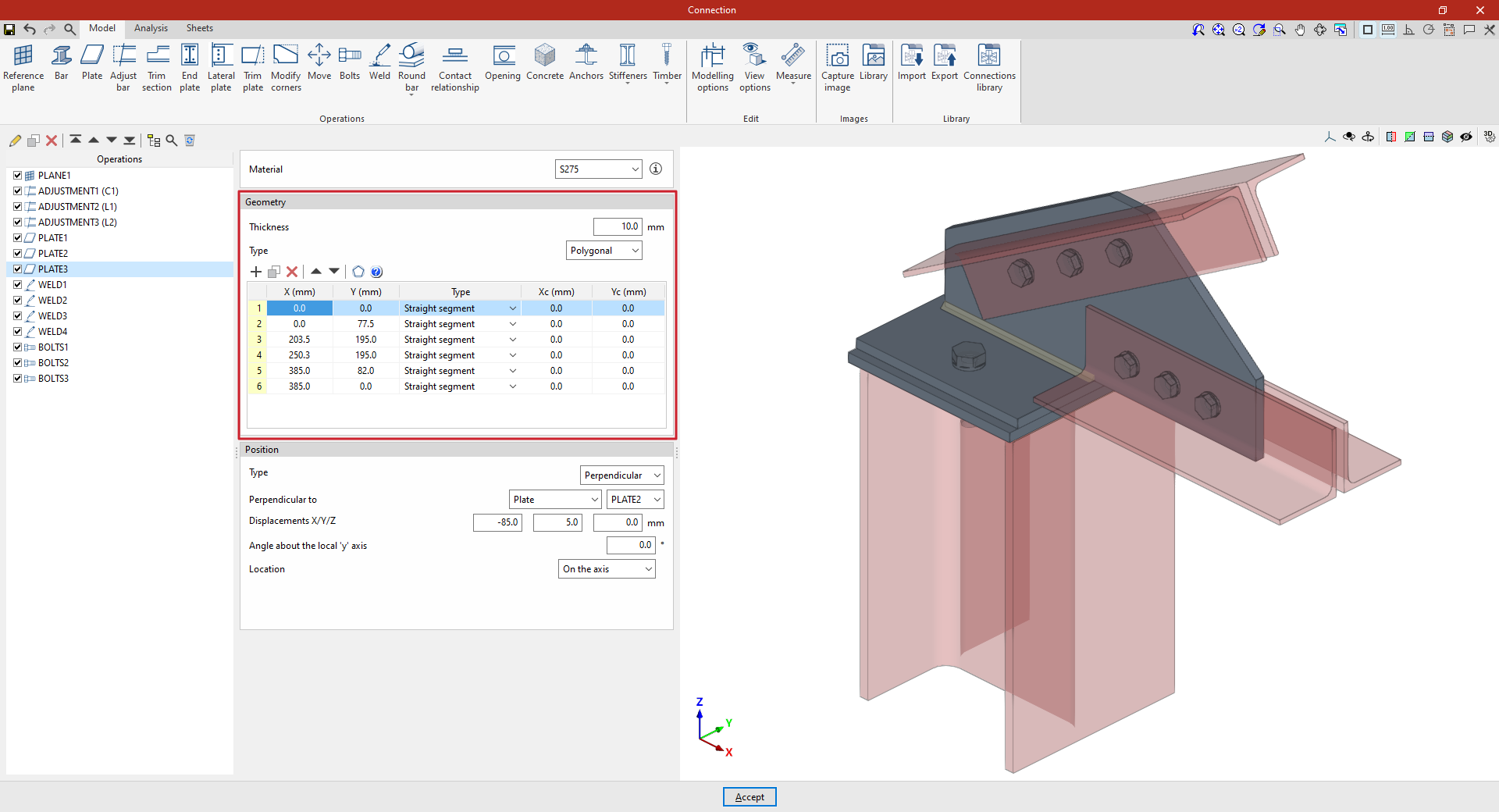
Polygonal plates
If “Polygonal” is selected, a table appears in which the geometry of the plate is defined by entering its vertices using coordinates:
- The options in the top bar allow you to "Add", "Copy", "Delete" and reorder vertices in the list.
- If it is a straight section, select "Straight span" in the "Type" column and define the "X" and "Y" coordinates of the starting vertex. The section will extend to the "X" and "Y" coordinates of the next vertex.
- If the section is curved, select "Curved span" in the "Type" column and define the coordinates of the centre of the arc, "Xc" and "Yc". The section will extend from the "X" and "Y" coordinates defined for it to the "X" and "Y" coordinates of the next vertex.
- The program also features a "Generate" tool at the top of the list, which allows you to automatically generate vertices for polygonal plates with straight sections by entering the "Number of sides" and the "Radius" of the circle circumscribed around the plate’s vertices. Using this tool will clear any data previously entered in the list.
- To make it easier to enter this data, the program displays a "Help" image when you click on the relevant button at the top of the list.
Defining the plate position
Finally, the “Position” of the plate is defined. The position of the plate may be relative to the centre of the “Connection”, or the plate may be “Attached” to or “Perpendicular” to another plate, another beam or a reference plane.
The inserted plate can be viewed in the 3D view on the right.
Plate positioned relative to the centre of the connection
In the “Type” drop-down menu, select “Connection” to define the position of the plate by entering the “X”, “Y” and “Z” coordinates relative to the centre of the connection.
If the plate needs to be rotated, you can enter the “Angle about the local ‘x’ axis”, the “Angle about the local ‘y’ axis” and the “Angle around the ‘Z’ axis”.
Panel attached to another element
To define the “Position”, select the “Attached” “Type”. This allows you to specify that the plate is “Attached to” another “Plate”, a “Section” or a “Reference plane”.
If required, you can enter an “X displacement”, a “Y displacement” and a “Z displacement”, as well as an “Angle around the local ‘z’ axis”, which allows you to adjust the position of the plate.
Finally, the “Location” of the plate is specified, which may be “On the front face”, “On the back face” or “On both faces”; in the latter case, two plates are produced.

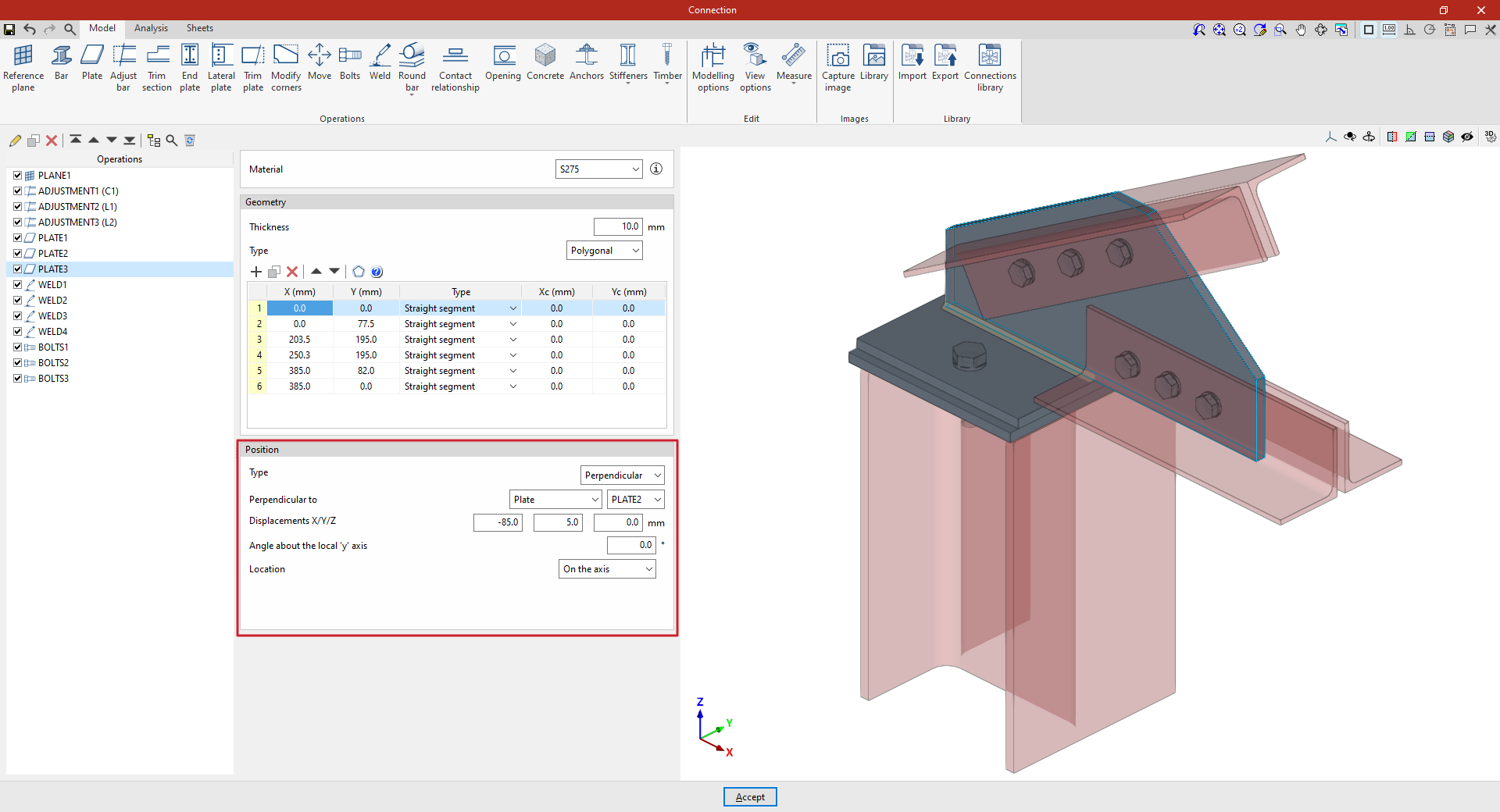
A plate perpendicular to another component
If you select the “Perpendicular” option under “Position”, you can specify that the plate is “Perpendicular to” another “Plate”, a “Section” or a “Reference plane”, which can be selected from the drop-down menu on the right.
Next, enter the “X/Y/Z displacements”, which allow you to adjust the position of the plate in space. You can also enter an “Angle about the local ‘z’ axis”.
The “Location” of the plate is also indicated; this may be “On the front face”, “On the back face” or “On both faces”, in which case two plates are generated.
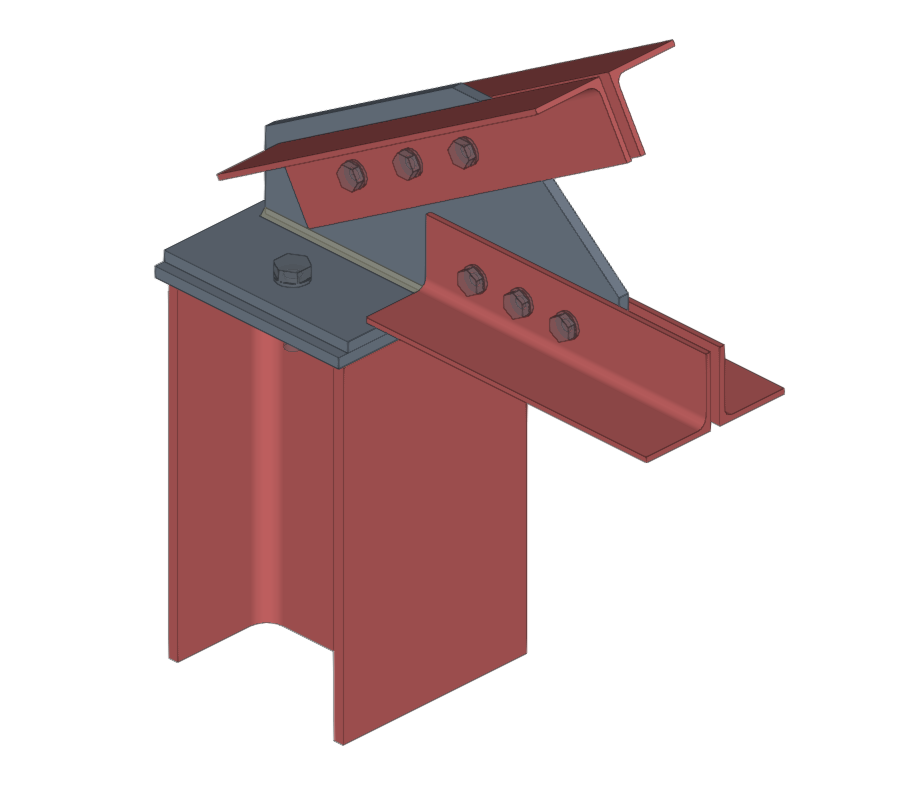
From this point onwards, the remaining operations required to complete the connection model—such as welds and bolts—must be added before the connection can be analysed.