

"Lateral plate" operation
The "Lateral plate" method involves joining sections together using a plate that is welded to one of them and bolted to the other.

Inserting lateral plates and selecting sections and material
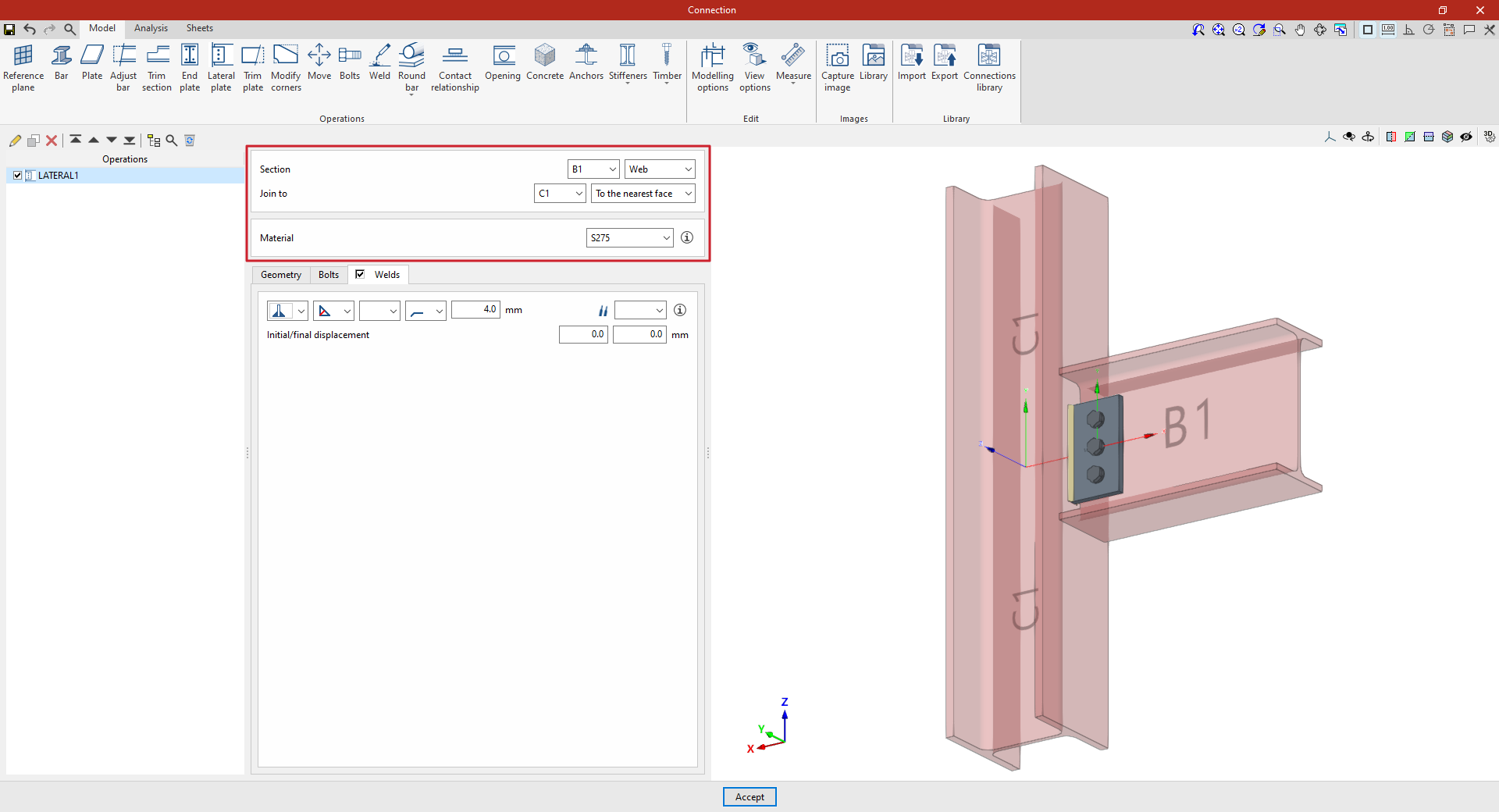
To insert a lateral plate, click on the "Lateral plate" option. Once the operation has been selected in the left-hand table, you can configure its parameters using the options in the central panel.
Use the drop-down menus at the top to select the “Section” where the plate is to be placed.
Next, under "Join to", select the bar to which the plate is to be joined. This can be done "To the nearest face", to the top flange ("Top Flange"), to the bottom flange ("Bottom Flange") or to the "Web" of that bar.
Next, select the “Material” of the plate from those available. The information button on the right allows you to view its specifications.
Defining the lateral panel geometry
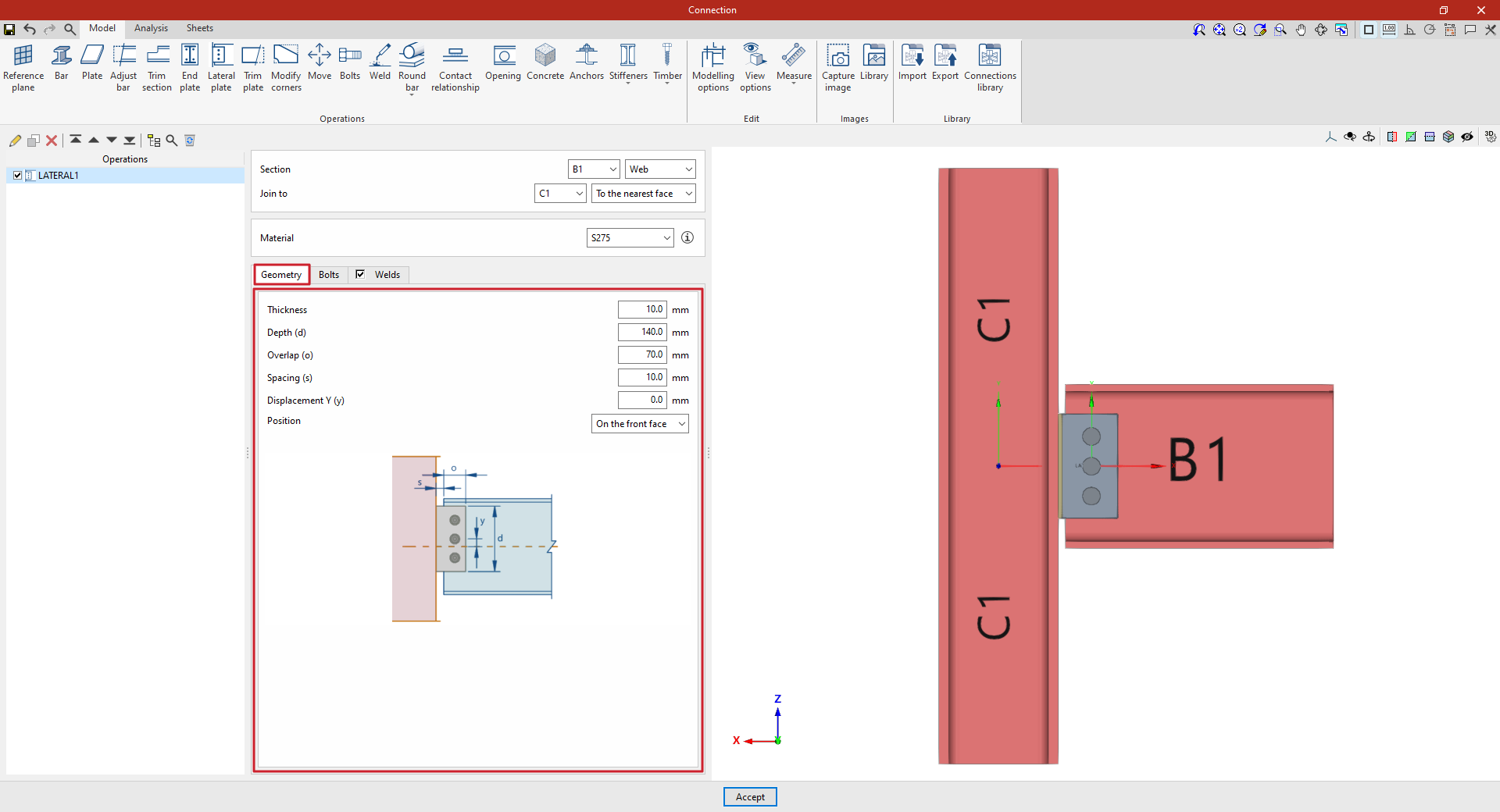
In the “Geometry” tab, the following parameters are defined:
- the “Thickness” and the “Depth (d)” of the lateral plate
- the “Overlap (or)” between the lateral plate and the section where it is fitted
- the “Spacing” between the section on which the sheet metal is placed and the section to which it is attached
- and a “Y-axis offset” of the sheet metal axis relative to the section axis on which it is placed.
You can use the help available via the button at the top right of this section to guide you through setting these values.
You also select the “Position” of the plate, which can be “On the front side”, as in this case, “On the back side” or “On both sides”.
Specifications for the lateral plate bolts
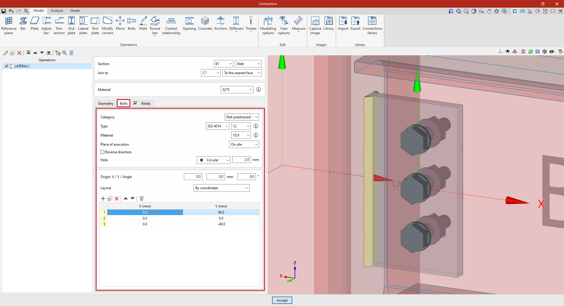
The “Bolts” tab is used to define the bolts that secure the end panel to the section on which it is placed.
First of all, the following parameters are defined:
- You must specify the "Category" of the bolt as either "Non-preloaded" or "Preloaded".
- Below, you can specify the “Type” of bolt by selecting its series and nominal diameter.
- The “Material” of the bolt is specified below.
- The drop-down menu below allows you to select the "Location", either "On site" or "At workshop".
- The "Reverse direction" box can be ticked to change the layout of the bolts.
- Finally, the bolt's "Hole" is specified. This can be:
- "Circular", in which case a "Space" is defined between the drill bit and the bolt,
- or "Elongated" in either of the two local directions (X or Y) of the sheet metal. In this case, the ratio between the length and the diameter of the hole ("L/d") is defined, with 1 being equivalent to a circle, as well as the "Space" between the hole and the bolt.
Next, in the following section, the bolts are positioned on the plate:
- You must define the local X and Y coordinates and the angle of the positioning origin for the bolts on the sheet metal by entering this data in the "Origin: X / Y / Angle" fields.
- Below, it is indicated whether the "Layout" of the bolts on the plate is:
- "By coordinates",
- By "Rows and columns",
- "Perimeter" on the sheet metal,
- Or "Radial".
| Note: |
|---|
| Further information on these layout options can be found via the following link. The local axes of the plate can be displayed in the viewer via the "Display options" to assist with configuring the bolt layout, with red representing the X-axis and green the Y-axis. |
Defining the lateral panel welds
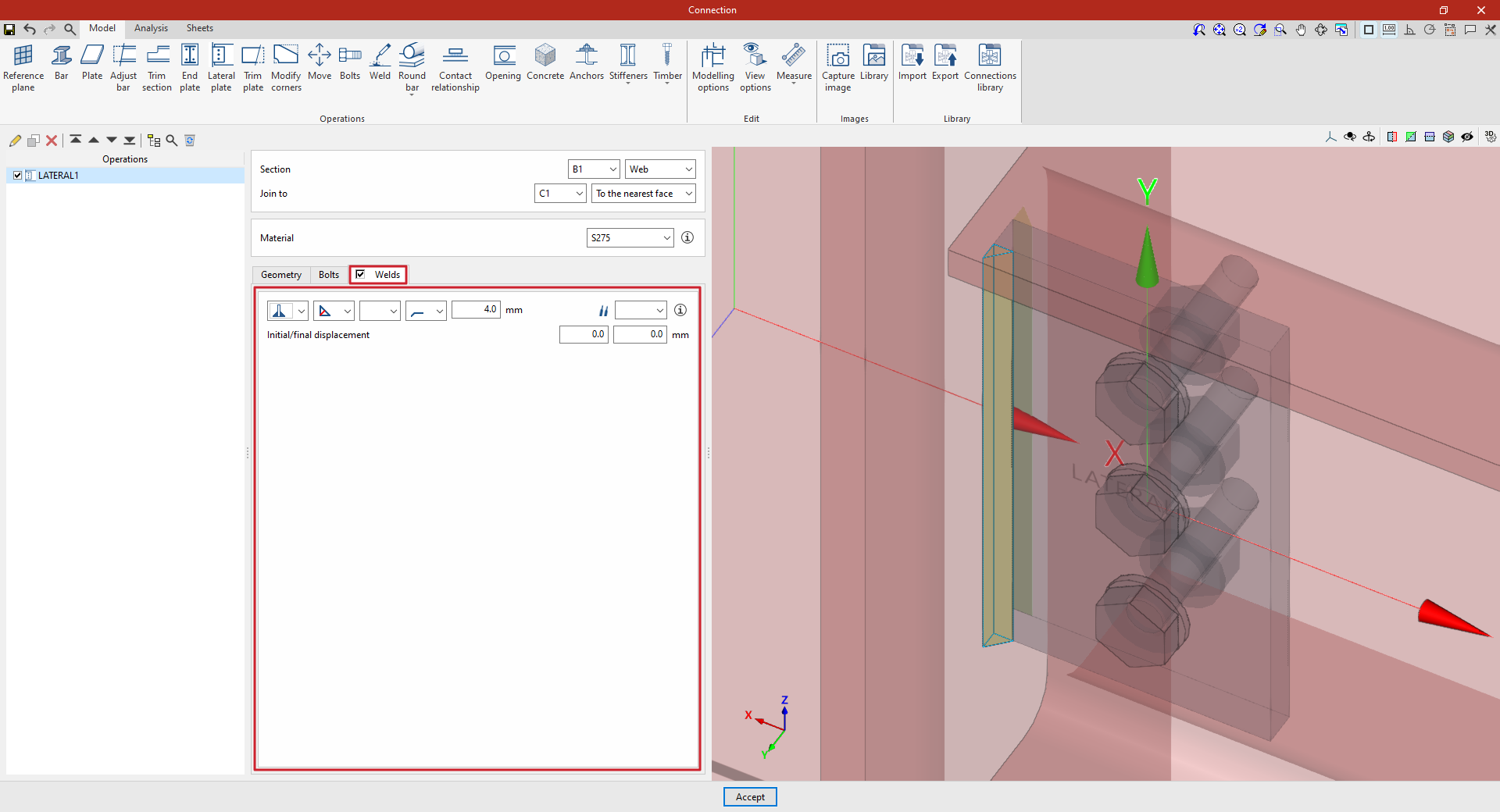
By selecting the “Welds” tab, you can define the welds that join the lateral plate to the bar it is attached to.
- The first drop-down menu shows various options for defining the position of the weld bead:
- On the left-hand side,
- On the right-hand side,
- Or on both sides.
- In the second drop-down menu, select the type of weld from the available options, which are as follows:
- At an angle, defined by the throat depth,
- At an angle, defined by the thickness of the weld side,
- Or flush-mounted with a double bevel.
- The third drop-down menu allows you to define the shape of the weld surface, which can be undefined, flat, concave, convex or with smooth transition curves.
- The fourth drop-down menu specifies the location where the work will be carried out, either on-site or at a workshop.
On the right, you can select the “Electrode” from those available. The information button on the right allows you to view its parameters, such as its reference number or the resistance of the filler metal.
Under “Initial/Final displacement”, you can specify the initial or final displacement values for the ends of the weld bead to adjust its length. If these values are set to zero, the default length is applied across the entire sheet.
Example
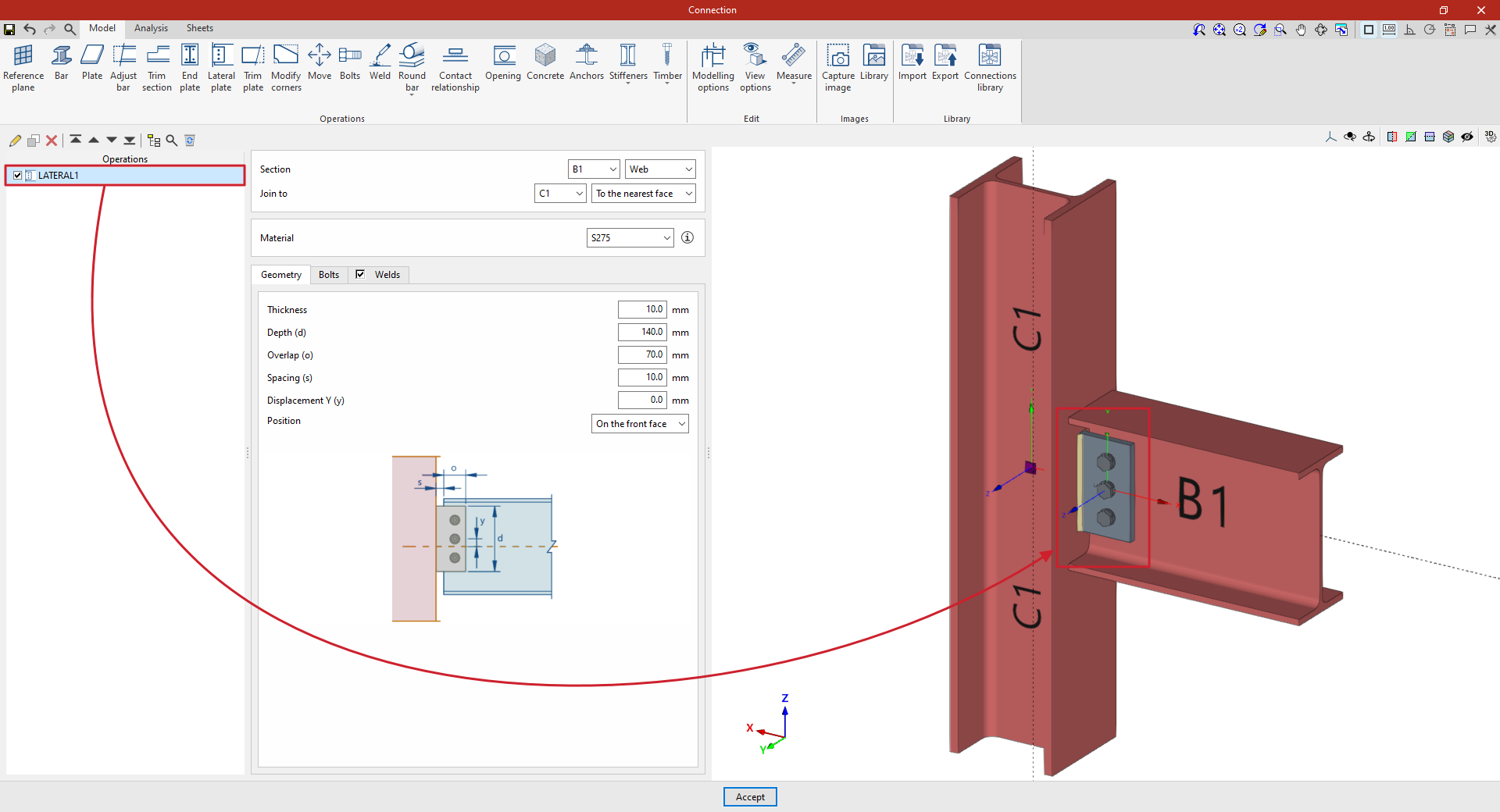
In the example shown here, a beam is connected to a column using a lateral plate:
- The plate is positioned on the “Web” of beam B1. It is then specified that it is to be “Join to” column C1, and specifically “To the nearest face”.
- In this case, S275 steel is selected.
- In “Geometry”, a “Thickness” of 10 millimetres, a “Depth (d)” of 140, an “Overlap (o)” of 70, a “Spacing (s)” of 10 and a “Y displacement (y)” of zero are defined.
- Three bolts are added with an “X” coordinate of 0 and “Y” coordinates of 40, 0 and −40 millimetres. Bolts from the ISO 4014 series with a nominal diameter of 12 are selected. The bolt “Material” is 10.9 steel. A “Clearance” of 2 millimetres is specified.
At this point, once the model has been finalised, you can continue by going to the "Analysis" tab to carry out the analysis of the connection.