

"Trim plate" function
The "Trim plate" operation allows you to trim a plate using another element. The cut can be made relative to the face of a section, a previously defined reference plane, or another plate.

Inserting a trim in a panel
To trim a plate, click on the “Trim plate” option in the top toolbar.
At the top of the central panel, select the “Plate” you wish to trim from the available options.
You are then prompted to specify whether you want to “Slice with” a “Beam”, another “Plate” or a “Reference plane”, after which you select the beam, plate or plane that defines the trim.
In the case of a beam, in addition to selecting it, you must specify the flange that defines the cross-section, such as the bottom flange (“Bottom flange”), the top flange (“Top flange”) or the “Web” of a double-T section.
The direction of the cut is indicated below; it can be either "On the front" or "On the back".
If desired, you can apply a “Displacement” to the cut-out to adjust its position, as well as add “Welds” by selecting the relevant option.
On the right, in the 3D view of the connection, you can see the effect of the trim made to the plate.
Example
In the example shown here, several plates have been added to connect the section, including top plates for the column and a vertical plate perpendicular to them.
In addition, section adjustments have already been carried out to modify their geometry.
A reference plane has also been defined for use in one of the plate cutting operations.
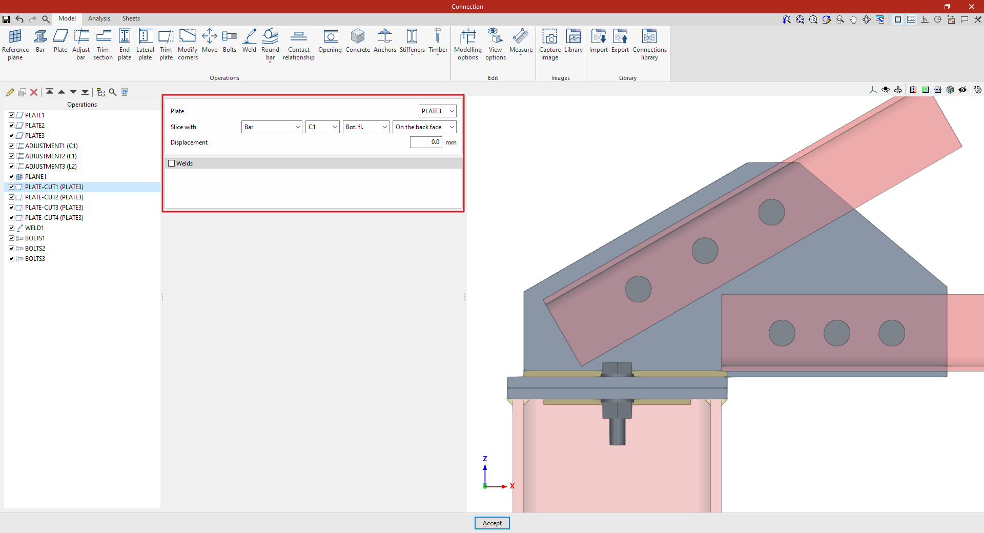
Next, cut-out operations are defined for the vertical plate ('PLATE3') that connects the angle sections to the top cap of the column:
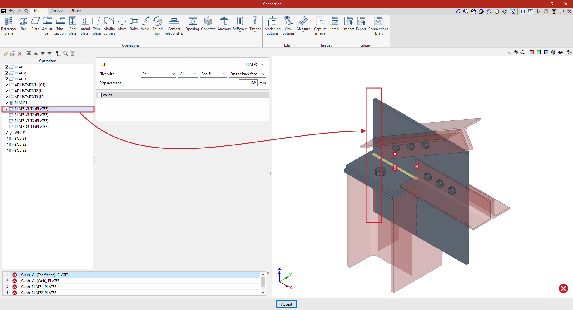
- In the first cut, select “Bar” C1, “Bottom flange”, and “On the back face”.
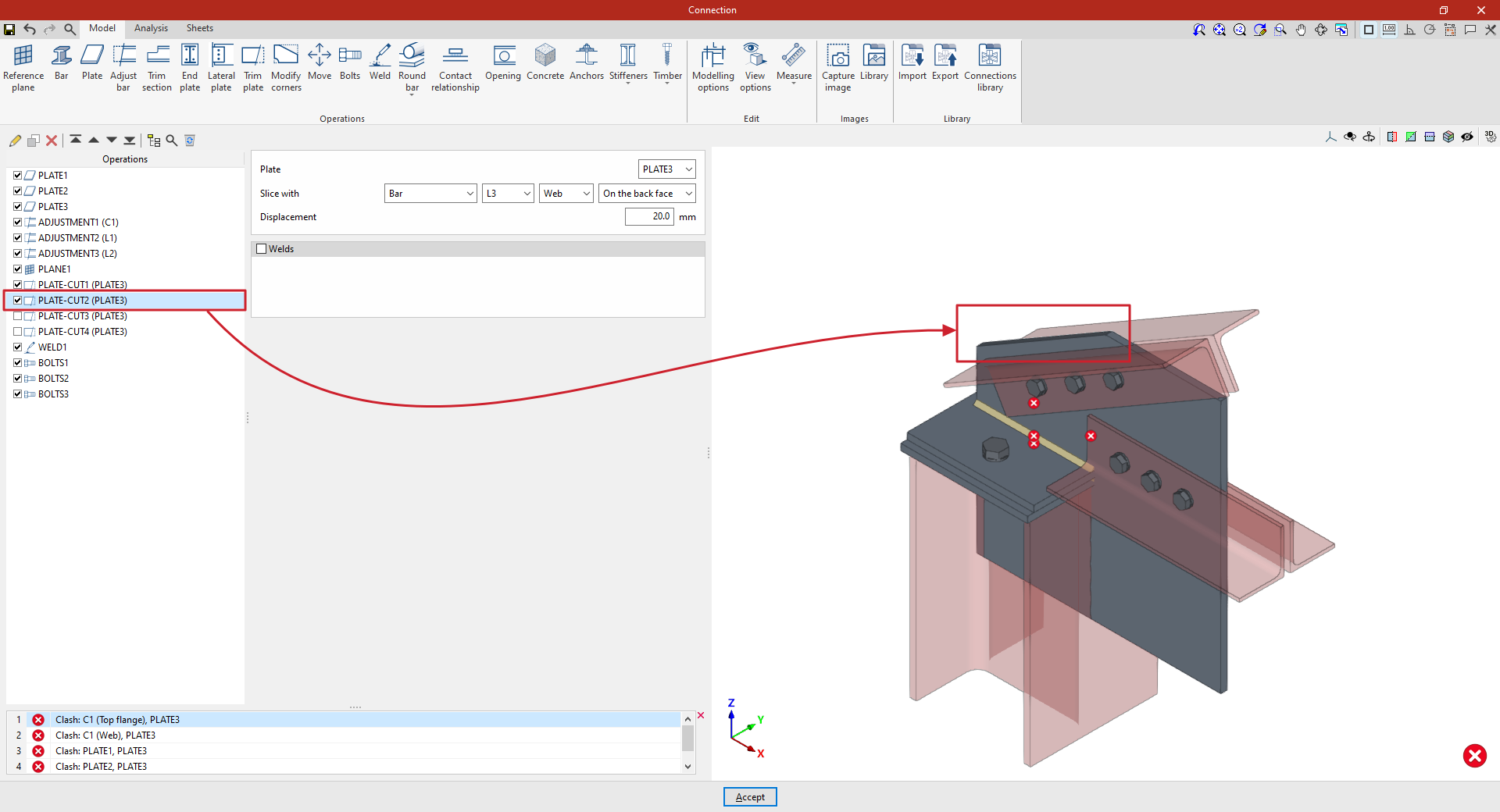
- To create a copy, select the operation in the left-hand table and click the “Copy” button at the top. Next, cut out the same “Plate” using “Section” L3 and, specifically, its “Web”, ensuring that the trim is made “On the back face”. In this case, enter an “Offset” of 20 millimetres.
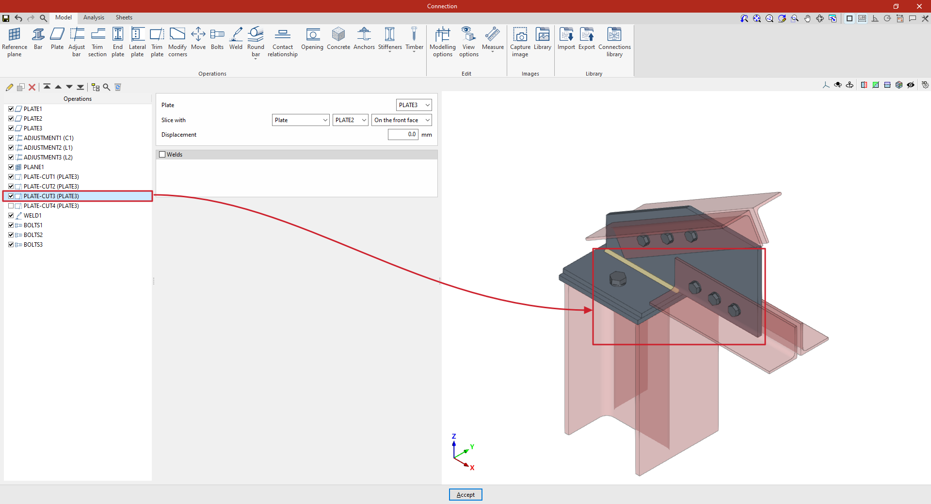
- The operation is repeated to perform a third trim. In this case, the cut is made using another “Plate”, by selecting its reference from the drop-down menu and then choosing “On the back face”.
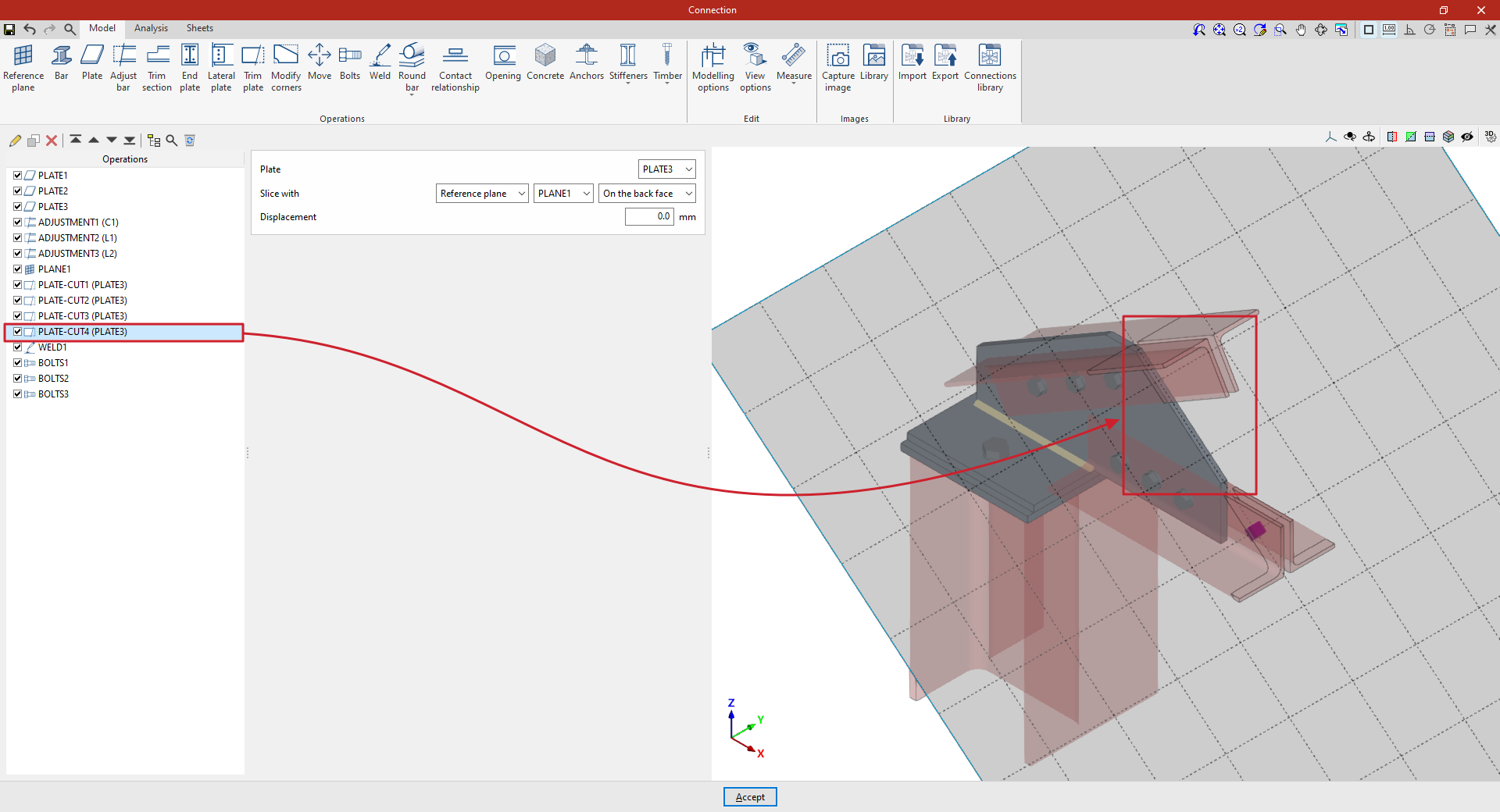
- Finally, a final cut-out is defined on the same “Plate” using a “Reference plane”. Select the plane reference from the drop-down menu and define a trim, once again, “On the back face”.
From this point onwards, the remaining operations required to complete the connection model must be added before the “Analysis” can be carried out.