Operation "Stiffeners": web stiffeners
The "Stiffeners" operation is used to insert stiffeners via a wizard in which their material, geometry, position and welds are defined.

Stiffeners can be inserted into the web of a section or into a plate.
Installation of web stiffeners
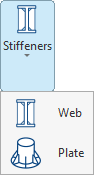
To insert web stiffeners, click on the “Stiffeners” option in the top toolbar to open the menu, then select “Web”.
| Example: |
|---|
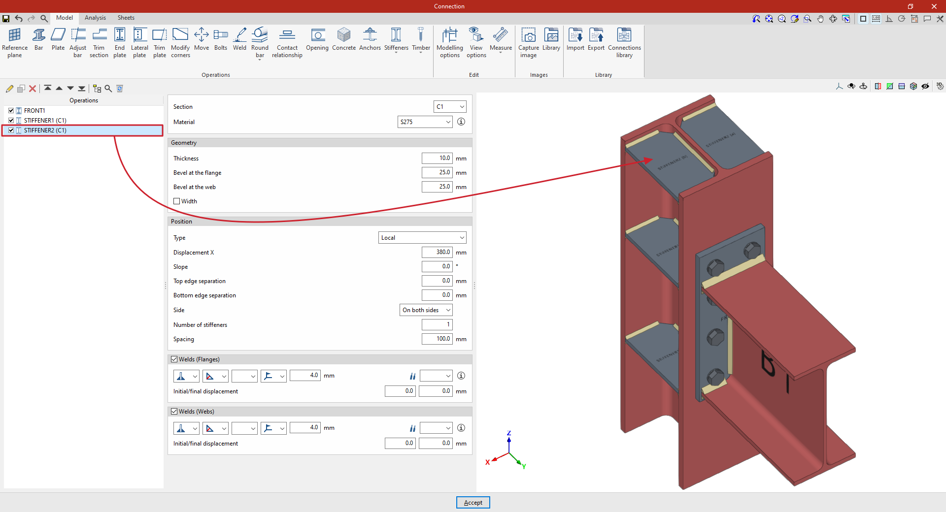
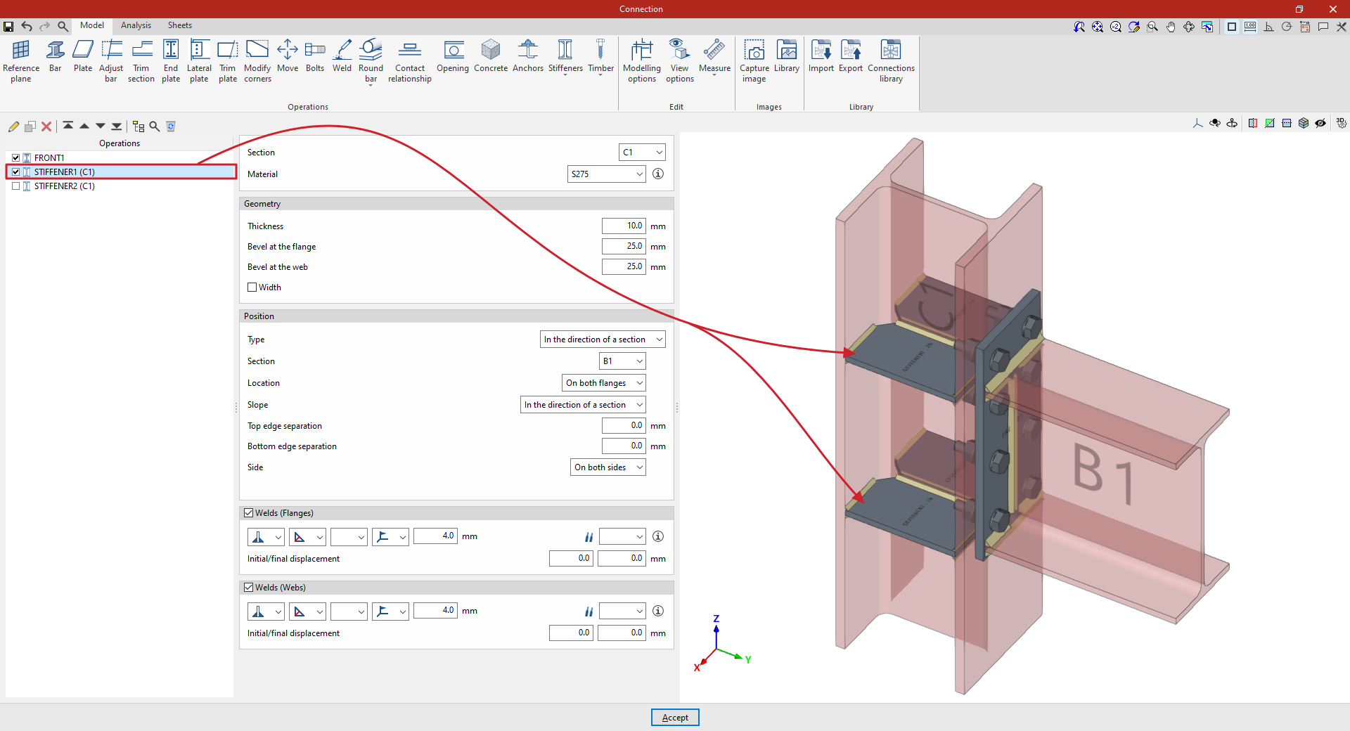
| In the example shown here, which illustrates a connection between a column and a beam, a flange has been added to connect the beam to the column. Next, stiffeners are added to the column to improve the performance of the connection. The first set of stiffeners is located on column C1, in the direction of beam B1. Angle welds are defined using the throat depth, with a dimension of 4 millimetres. The second set of stiffeners is located on column C1 in an upper position, independent of the beam’s position. In the “Position” section, “Local” is selected in this case, and the necessary parameters are specified. From here, once the model is complete, users can continue by opening the “Analysis” tab to perform the analysis of the connection. |
Selecting the section and material for the stiffeners
First, select the “Section” where the stiffeners are located.
Next, select the “Material” for the stiffeners from the drop-down menu.
If you click on the button on the right, you can view the “Reference” and properties of the selected material, such as the “Modulus of elasticity”, “Poisson’s ratio”, “Coefficient of thermal expansion”, “Specific weight”, “Yield strength” and “Fracture limit”. In addition, the “Resistance depending on the thickness” is shown.
Defining the geometry of the stiffeners
The following section allows you to define the “Geometry” of the stiffeners.
Here, you enter the values for “Thickness”, “Bevel at the flange” and “Bevel at the web”.
Optionally, you can tick the relevant box to indicate that the “Width” of the stiffeners is different from that of the section in which they are located.
Specifying stiffener welds
If required, the welds connecting the stiffener to the flanges and webs of the section can be defined directly by ticking the boxes in the relevant sections at the bottom of the panel (“Welds (Flanges)” and “Welds (Webs)”).
Within each section, the drop-down menus display various options for specifying the position of the weld, the type of weld, the shape of its surface and the location where it is to be carried out, either on-site or at a workshop.
It is also possible to select the “Electrode” and specify whether the welds have an initial displacement or a final displacement (“Initial/final displacement”). By default, the program places the weld on the flat part of the web, interrupting the weld bead at the radius specified in the section.
Defining the position of the stiffeners
The "Position" section defines the position of the stiffeners.
In the “Type” drop-down menu, select “Local” or “In the direction of a section”:
Stiffeners along the length of a section
In this case, the stiffeners follow the path of a specific “Section”, which must be selected from the drop-down menu.
Next, the “Location” of the stiffeners is configured. This can be on the “Top flange”, the “Bottom flange”, “On both flanges” or the “Centre”.
On the other hand, the “Slope” can be “Local” or defined “In the direction of a section” (i.e. in the direction of the previously selected section).
To adjust the geometry of the stiffener, you can also enter a “Top edge separation” and a “Bottom edge separation”.
Below, it is indicated whether the stiffeners are located on the “Left”, “Right” or “Both sides” of the section.
Local stiffeners
To add stiffeners to a bar at any position, select “Local” in the “Position” section. This allows you to specify the position of the stiffener freely, without being constrained by the geometry of another bar.
To do this, enter the value for “X displacement”, which follows the section’s local X-axis.
You must also specify the “Slope” of the stiffener by entering its value in degrees.
Next, as in the previous case, enter the “Top edge separation” and the “Bottom edge separation”, and specify the “Side” of the section where the stiffeners are to be placed, whether “Left”, “Right” or “On both sides”.
Finally, the “Number of stiffeners” is specified; this may be one or more, in which case the “Spacing” between them is also stated.