

Inserting and defining shear lugs
Shear keys are steel sections welded to the underside of an anchor plate and embedded in the concrete; they allow shear forces to be transmitted directly to the foundation element, thereby freeing the anchor bolts to act solely in tension.
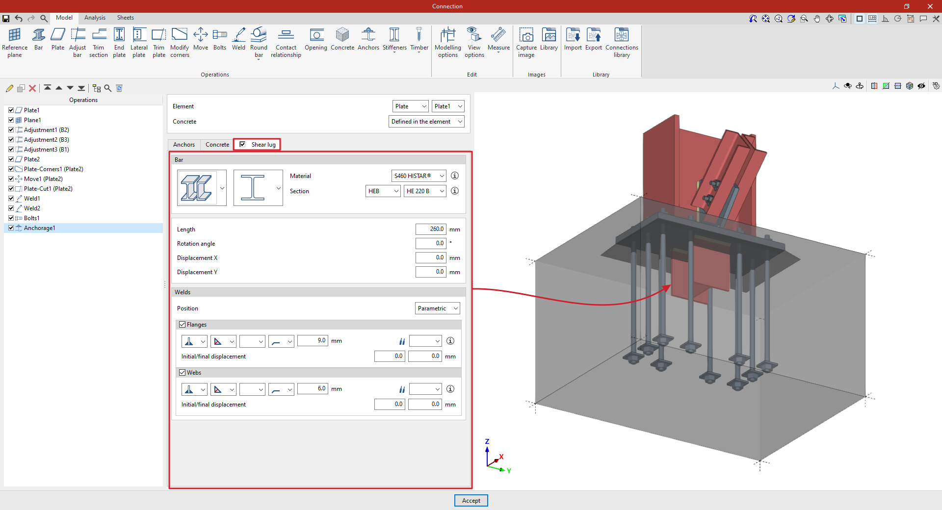
Shear keys can be defined for the anchor plates entered in the program. To do this, in the "Anchors" operation, tick the “Shear lug” box in the relevant tab.
| Example: |
|---|
| In the example shown here, a plate has been added to the base of the column, adjustments have been made to the geometry of the sections, and another plate has been inserted and adjusted to form the connection between them, together with the necessary welds and bolts. Finally, an anchoring operation has been inserted by selecting the first plate, thereby indicating that it is a baseplate on the concrete of the foundation element. Furthermore, angle weld beads have been defined, specifying the thicknesses of the grooves. |
Selecting the bar, material and section of the shear lugs
To define the cutting tool, you must first specify the “Bar” parameters, such as its type, and select the “Material” and “Cross-section” from those available in the library, which can be configured in advance via the relevant option in the main interface.
Defining the geometry and position of the shear lug
Next, its geometric properties are defined, such as the “Length” of the shear lug from the plate, the “Rotation angle”, as well as the “X displacement” and “Y displacement” relative to the element’s local axes.
Defining shear lug welds
Next, the “Welds” between the baseplate and the shear lug are defined. The “Position” of the weld can be “Perimeter”, encircling the entire section, or “Parametric”. In this case, the welds on the “Flanges” and the “Web” are defined.
Within each section, the drop-down menus display various options for specifying the position of the weld, the type of weld, the shape of its surface and the location where it is to be carried out, either on-site or at a workshop.
You can also select the “Electrode” and specify whether the welds have an “Initial displacement” or a “Final displacement”.
At this point, once the model is complete, you can continue by opening the “Analysis” tab to perform the analysis of the connection.
| Note: |
|---|
| The strength of the concrete element for shear lugs is verified by testing the compressive strength on the faces of the shear lug. |