"Anchors" function
The "Anchors" function is used once an element, such as a plate or a section, has been inserted, and allows you to add anchors to it.

Anchors are installed in the same way as bolts. In addition, shear lugs can be inserted to transfer shear forces to the foundation element.
Inserting anchors
To insert anchors, click on the “Anchors” option in the top toolbar.
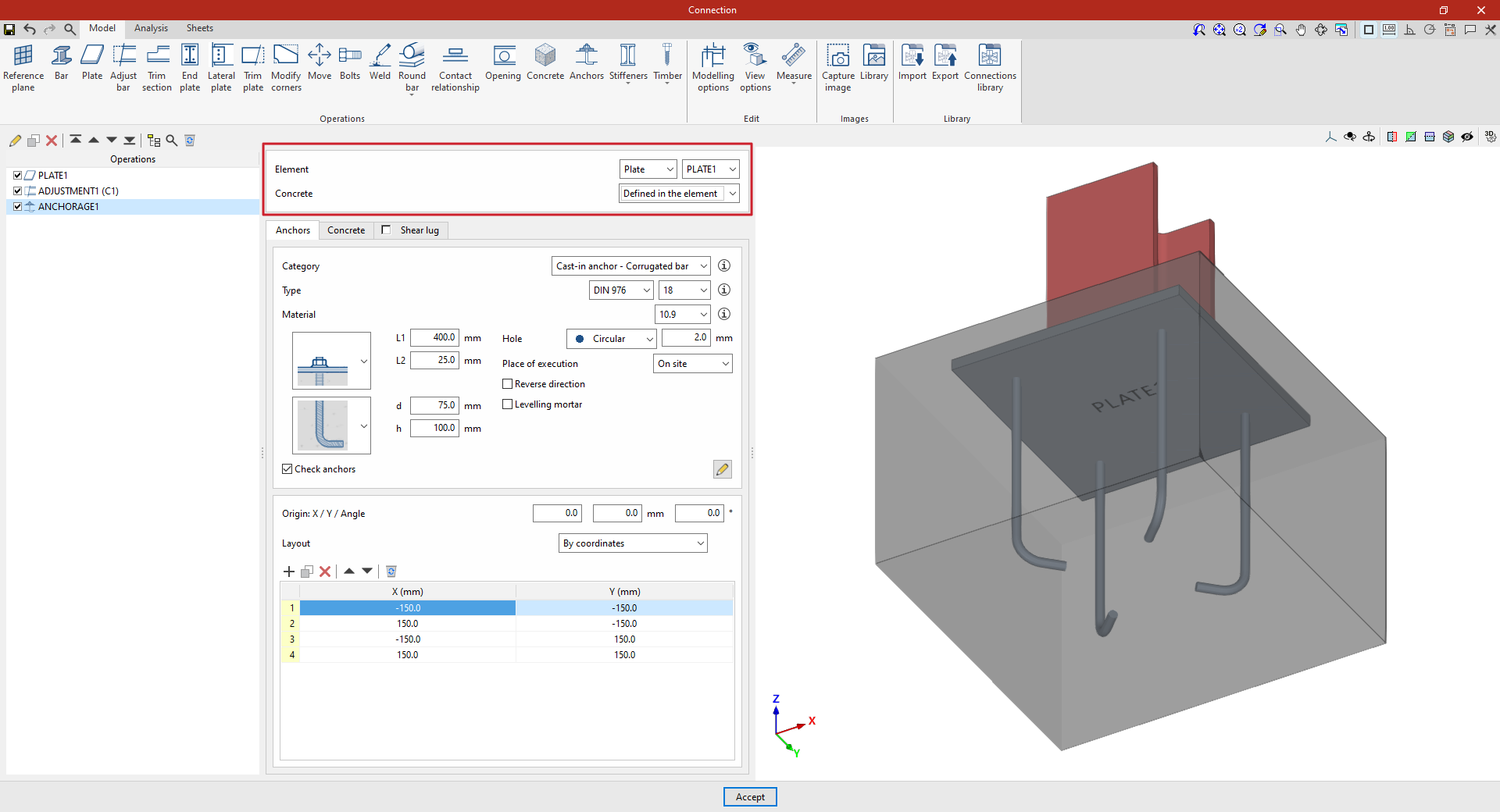
First, select the "Element" where the anchors are to be defined; this can be a "Plate" or a "Section". If you select a section, you must then select the plate or part of the section where you wish to insert the anchors.
Next, you decide whether the “Concrete” is “Defined in the element” or whether you wish to “Select” a concrete element entered via a separate operation.
Defining anchors
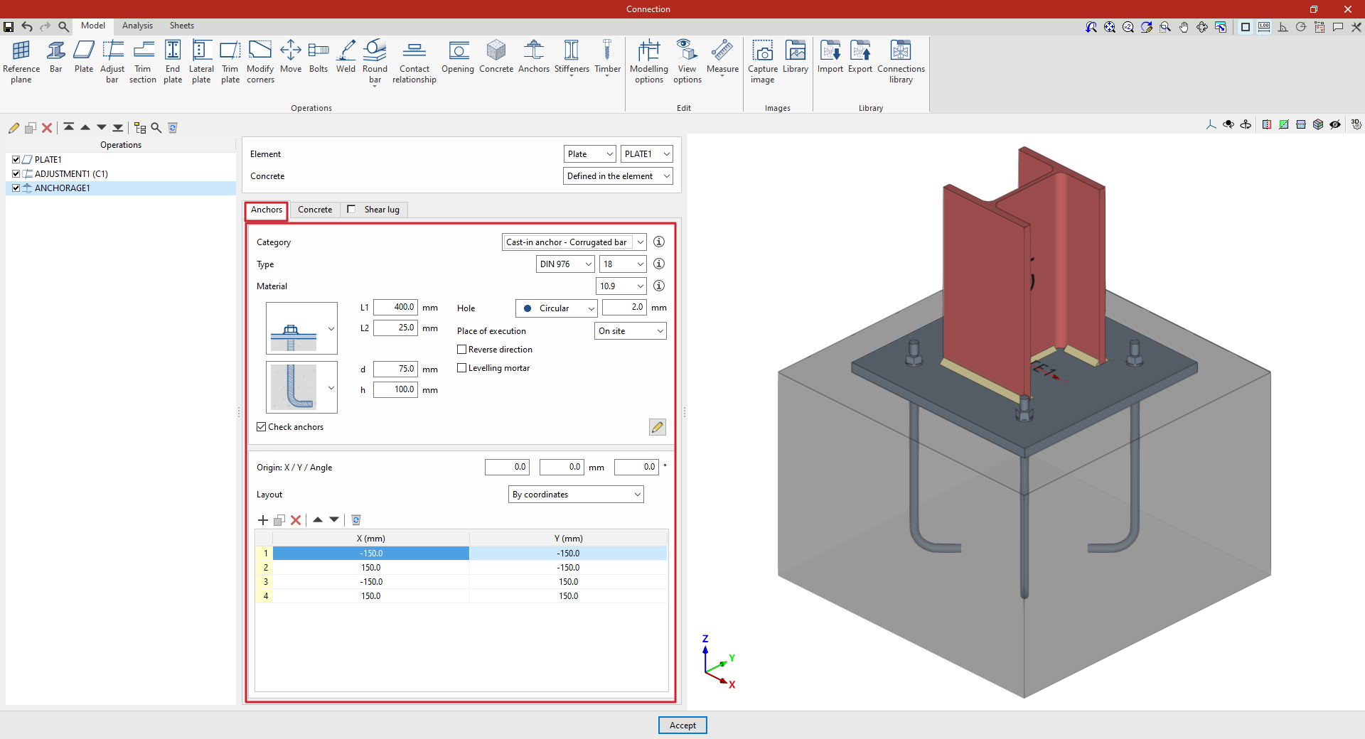
In the "Anchors" tab, you can configure and position the anchors:
| Example: |
|---|
| In the example shown here, a plate has been added to the base of column C1, and an adjustment operation has been performed on it to modify its geometry and insert the welds between the section and the plate. Next, the anchors are added to create the connection between the plate and the foundation concrete. In this case, select “Plate” and choose the plate available from the drop-down menu on the right. To manually define the position of the anchors, click on “Add” and enter the “X” and “Y” coordinates relative to the element’s local coordinate system. |
Anchor configuration
First, the following parameters are defined:
- You must select the anchor's "Category" from the following:
- "Cast-in anchor – Corrugated bar",
- "Cast-in anchor – Threaded rod",
- "Cast-in anchor – Smooth bar",
- or "Cast-in anchor".
- Further down, you can select the “Type” of anchor, choosing its series and nominal diameter from those available. If you wish, you can click on the button on the right to open a window where you can view details such as the following:
- For the “Bolt”, the series reference, the “Nominal diameter” and the “Diameter of the thread” are shown.
- In the case of the “Nut” and the “Washer”, the series codes and nominal diameter are also given, along with the “Outer diameter”, “Inner diameter” and “Thickness” of each.
- Next, select the “Material” of the anchor. By clicking on the button on the right, you can view its properties, including its “Reference”, “Modulus of elasticity”, “Yield strength” and “Fracture limit”, as well as the material of the “Nut” and the “Washer”.
Two drop-down menus then appear to allow you to select the type of anchor. These drop-down menus vary depending on the selected anchor "Category".
For example, in pre-installed rebar anchors:
- In the first drop-down menu, select the type of connection between the bolt and the plate, which can be flush-mounted with a washer and single nut, flush-mounted with a welded bolt, spaced, or spaced with a nut and washer.
- The second drop-down menu allows you to select the type of concrete anchor, which can be a straight extension, with a washer and single nut, with a double nut, with a 180-degree hook, or with a 90-degree bend.
The program asks you to define the parameters corresponding to various geometric dimensions, such as “Ln”, “L1”, “L2”, “d” or “h”. To make it easier to enter this data, a help image is available via the button to the right of the “Category” drop-down menu.
On the right, you can specify the following additional parameters:
- The anchor's "Hole" is defined later on. This can be:
- "Circular", in which case a "Space" is defined between the drill bit and the anchor
- Or "Elongated" in either of the two local directions (X or Y) of the sheet metal. In this case, the ratio between the length and the diameter of the hole ("L/d") is defined, with a value of 1 corresponding to a circle, as well as the "Space" between the hole and the anchor
- The drop-down menu below allows you to select the "Location", either "On site" or "At workshop".
- The "Reverse direction" checkbox can be ticked to change the orientation of the anchors.
- It is also possible to apply a layer of “Levelling mortar” between the element and the concrete, specifying its thickness.
Finally, the "Check anchors" checkbox can be ticked to enable the program to carry out checks on these elements. The button on the right opens a pop-up window where you can configure the parameters and factors to be taken into account in these checks.
Layout of the anchors
The following section then specifies the number and layout of the anchors:
- You must define the local X and Y coordinates and the angle of the positioning origin for the anchors on the plate or bar by entering this data in the "Origin: X / Y / Angle" fields.
- Below, it is indicated whether the "Layout" of the anchors on the plate or bar is:
- "By coordinates",
- By "Rows and columns",
- By "Rows and columns per flange" (in front plates on rolled I sections),
- "Perimeter" on the sheet metal,
- Or "Radial".
| More information: |
|---|
| Further information on these layout options can be found via the link below. |
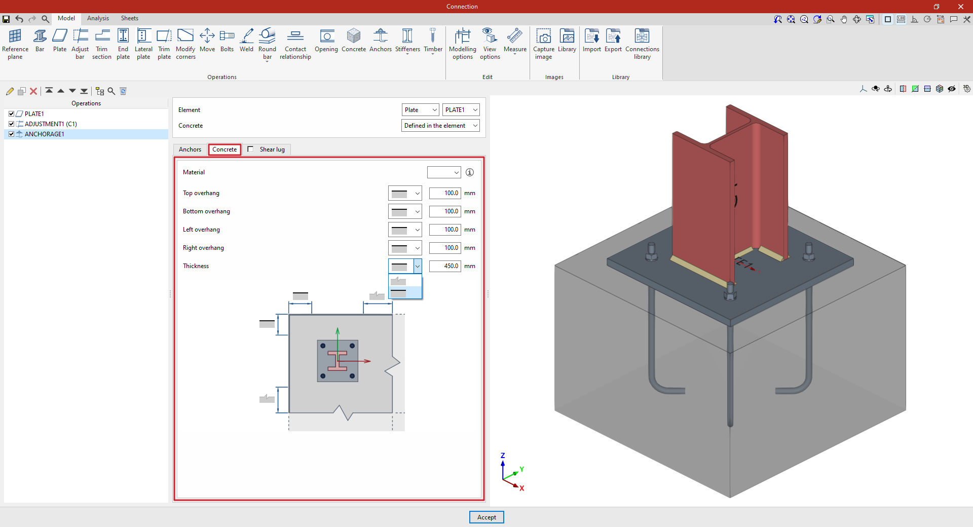
Defining a concrete element
The “Concrete” tab allows you to define the concrete element of the anchor in this same operation and appears if this has been specified previously (by selecting “Defined in the element” in the “Concrete” section).
First, specify the “Material” by selecting it from the concrete options available in the project. The button on the right allows you to view the parameters of the selected concrete, such as the “Reference” or the “Compression resistance”.
Finally, the geometry of the concrete volume is defined using the values for the "Top edge", "Bottom edge", "Left edge", "Right edge" and "Thickness", measured from the outline of the selected slab. For each of these, you must indicate whether the concrete element is limited to these values or extends beyond them by selecting the corresponding option from the drop-down menu.