

"End plate" function
The "End plate" operation allows one section to be joined to another using an end plate. You can weld the section to the plate and insert bolts between the plate and the section.

Inserting the end plate and selecting the section and material
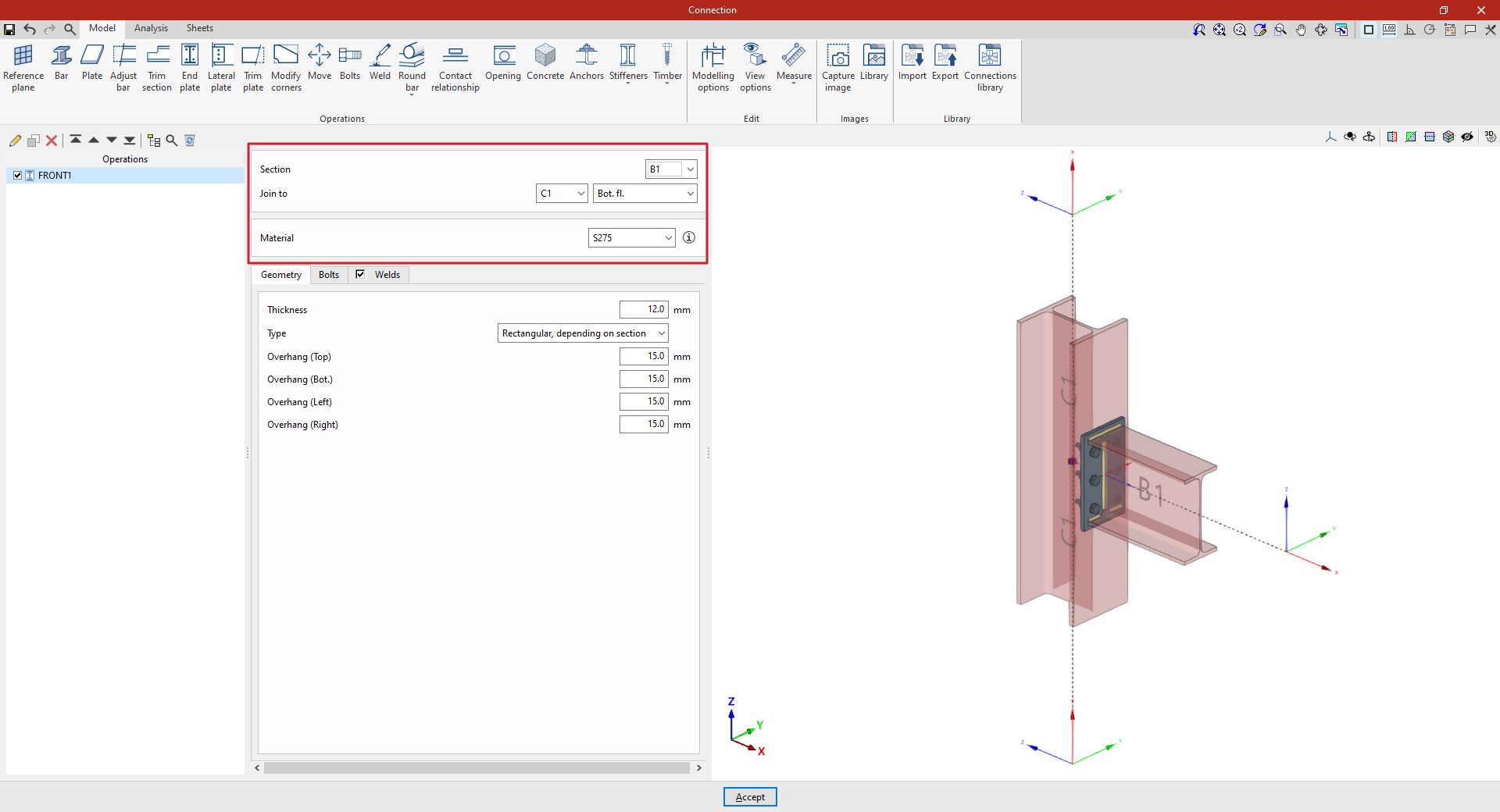
To insert an end plate, click on the “End plate” option. Once the operation has been selected in the left-hand table, you can configure its parameters using the options in the central panel.
Use the drop-down menus at the top to select the “Section” where the plate is to be placed.
Next, under "Join to", select the bar to which the plate is to be joined. This can be done "To the nearest face", to the top flange ("Top flange"), to the bottom flange ("Bottom flange") or to the "Web" of that bar.
Next, select the “Material” of the plate from those available. The information button on the right allows you to view its specifications.
| Note: |
|---|
| You can use the “Display Options” to identify the upper or lower flange of the sections. To do this, display the “Sections” and “Plates” as transparent by clicking on the cells in the “Drawing” column, and also enable the display of the “Axes”. After clicking “Accept”, you will see that the Z-axis of each beam, shown in blue, points towards its top flange. |
Defining the end plate geometry
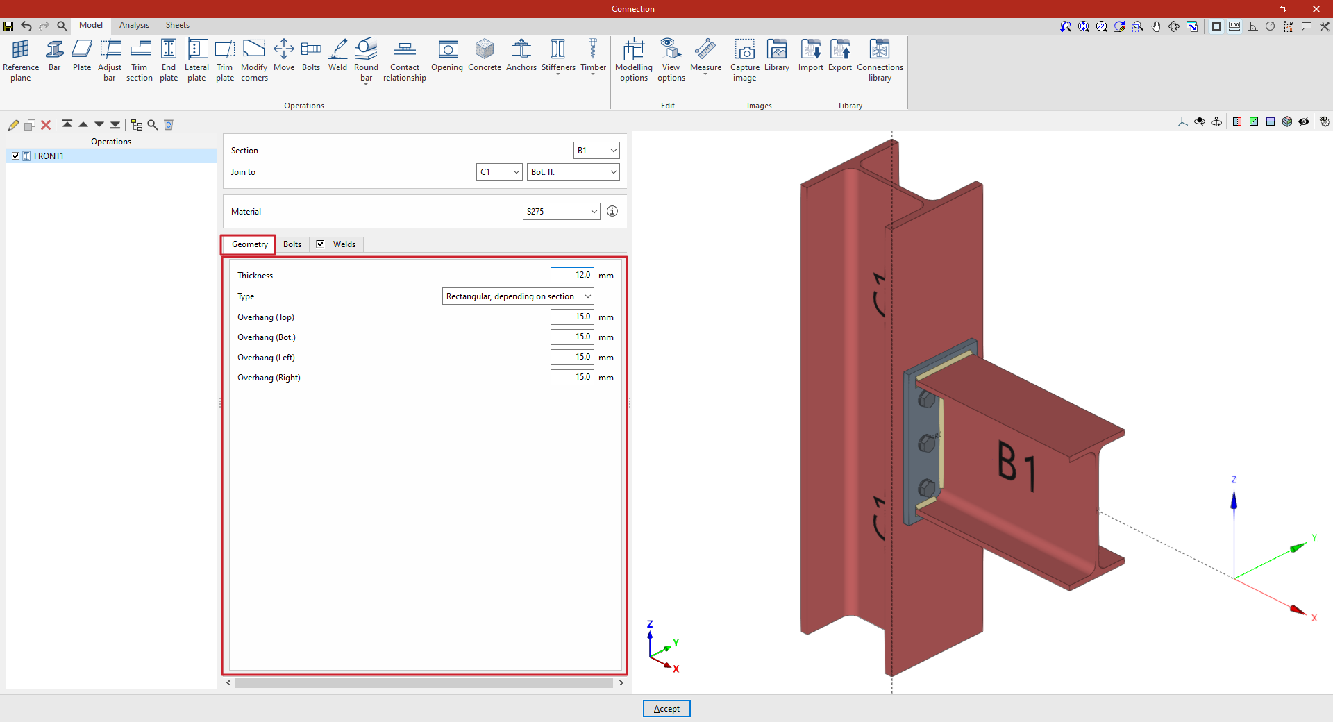
In the “Geometry” tab, you define the “Thickness” of the plate.
Next, select the type of plate from the “Type” drop-down menu. This can be:
- “Rectangular, based on section”, defining the top, bottom, left and right overhangs based on the selected section (“Top overhang”, “Bottom overhang”, “Left overhang” and “Right overhang”);
- “Rectangular”, entering the dimensions of the plate directly using “Width X” and “Width Y”;
- or "Circular", in which case the "Diameter" is specified.
Defining the end plate bolts
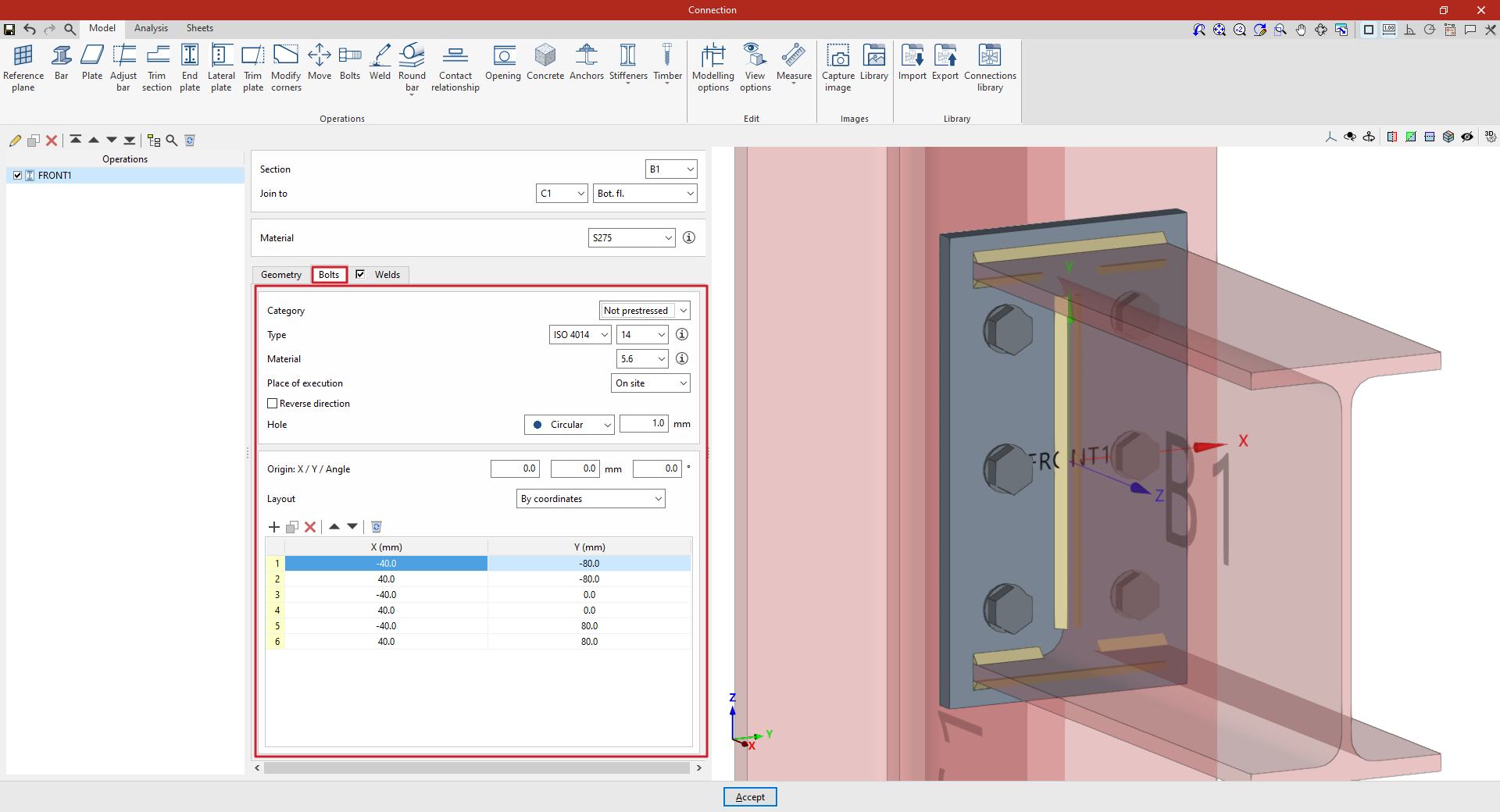
The “Bolts” tab is used to specify the bolts that secure the end plate to the bar.
First of all, the following parameters are defined:
- You must specify the "Category" of the bolt as either "Non-preloaded" or "Preloaded".
- Below, you can specify the “Type” of bolt by selecting its series and nominal diameter.
- The “Material” of the bolt is specified below.
- The drop-down menu below allows you to select the "Location", either "On-site" or "In workshop".
- The "Reverse direction" box can be ticked to change the orientation of the bolts.
- Finally, the bolt's "Hole" is specified. This can be:
- "Circular", in which case a "Space" is defined between the hole and the bolt,
- or "Elongated" in either of the two local directions (X or Y) of the sheet metal. In this case, the ratio between the length and the diameter of the hole ("L/d") is defined, with 1 being equivalent to a circle, as well as the "Space" between the hole and the bolt.
Next, in the following section, the bolts are positioned on the plate:
- You must define the local X and Y coordinates and the angle of the positioning origin for the bolts on the sheet metal by entering this data in the "Origin: X / Y / Angle" fields.
- Below, it is indicated whether the "Layout" of the bolts on the plate is:
- "By coordinates",
- by "Rows and columns",
- by "Rows and columns per flange" (in end plates on rolled I sections),
- "Perimeter" on the sheet metal,
- or "Radial".
| Note: |
|---|
| Further information on these layout options can be found via the following link. The local axes of the plate can be displayed in the viewer via the "Display options" to assist with configuring the bolt layout, with red representing the X-axis and green the Y-axis. |
Defining the welds on the end plate
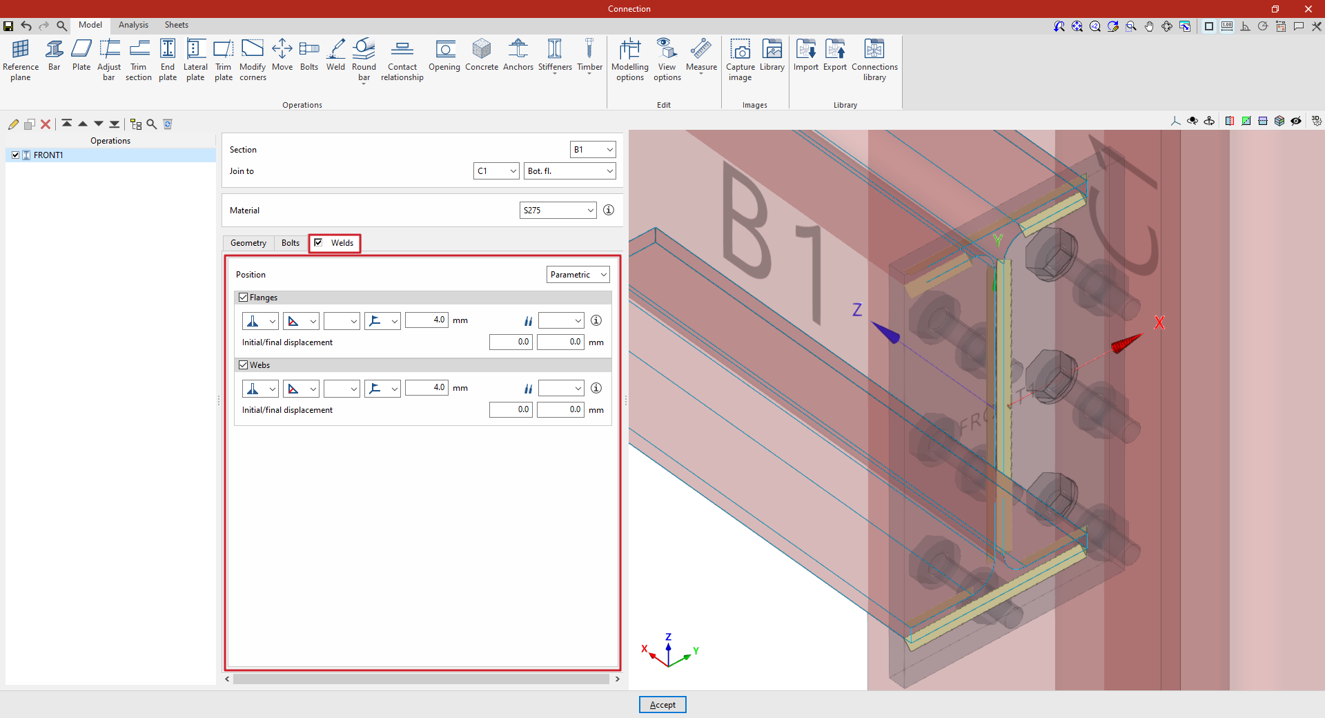
By selecting the “Welds” tab, you can directly define the welds that join the end plate to the sections on which it is located.
The program allows you to specify a "Perimeter" weld along the contour of the section, or a "Parametric" weld, in which case you must specify the "Welds" for the "Flanges" and the "Webs" by ticking the relevant boxes. Within each section:
- The first drop-down menu shows various options for defining the position of the weld bead:
- On the left-hand side,
- On the right-hand side,
- Or on both sides.
- In the second drop-down menu, select the type of weld from the available options, which are as follows:
- At an angle, defined by the throat depth,
- At an angle, defined by the thickness of the weld side,
- Or flush-mounted with a double bevel.
- The third drop-down menu allows you to define the shape of the weld surface, which can be undefined, flat, concave, convex or with smooth transition curves.
- The fourth drop-down menu specifies the location where the work will be carried out, either on-site or at a workshop.
On the right, you can select the “Electrode” from those available. The information button on the right allows you to view its parameters, such as its reference number or the resistance of the filler metal.
You must specify whether the welds have “Initial/Final displacement” values. By default, the program places the weld on the flat part of the web, interrupting the weld bead at the radius specified by the section.
Example
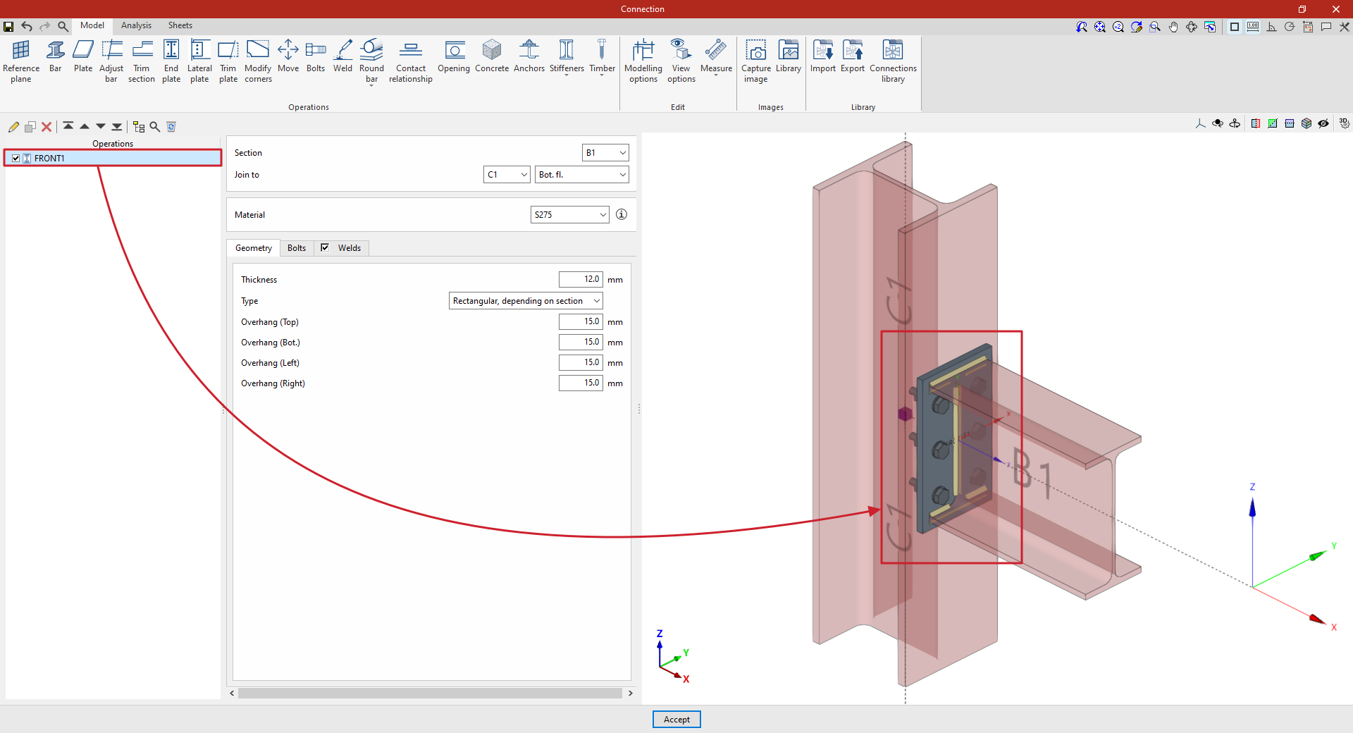
In the example shown here, an end plate is inserted to connect a beam to a column using an end plate:
- The beam is positioned on the "Section" of beam B1, which is to be "Joined to" column C1, specifically to its "Bottom flange". In this case, S275 steel is selected.
- The “Thickness” is 12 millimetres. The type is “Rectangular, depending on section”, and a value of 15 millimetres is entered for all sides.
- Non-prestressed bolts from the ISO 4014 series, with a nominal diameter of 14 mm and made of 5.6 grade steel, are selected. “Circular” type holes with a “Space” of 1 millimetre are specified.
- There are three rows and two columns of bolts, and angled weld beads are defined by the groove depth, which measures 4 millimetres.
At this point, once the model has been completed, you can continue by going to the "Analysis" tab to carry out the analysis of the connection.