"Contact relationship" function
The "Contact relationship" function allows you to simulate contact between steel surfaces or between steel surfaces and concrete elements.

Entering contact details
To define contact relationships between surfaces, click on the “Contact relationship” option in the top toolbar.
Next, the two elements involved in the connection are selected, and the parts of each that are in contact are indicated.
Connections can be defined between steel surfaces or between steel surfaces and concrete elements.
Contact relationships are represented in the 3D view of the layout by a green surface located between the elements selected in the operation.
| Note: |
|---|
| Where bolt connections between two elements have been defined, these contact relationships are established automatically by the program, just as when a plate is joined to a concrete element using anchors. |
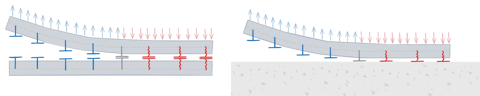
Contact between steel surfaces
In the relationships defined between steel surfaces, the elements involved in the relationship are selected in the "Element 1" and "Element 2" sections. These can be a “Section” or a “Plate”.
If a "Section" is selected, the part of the section involved in the connection is specified, such as the top flange ("Top flange"), the bottom flange ("Bottom flange"), the left web ("Left web"), or the right web ("Right web") of rectangular tube sections.
| Example: |
|---|
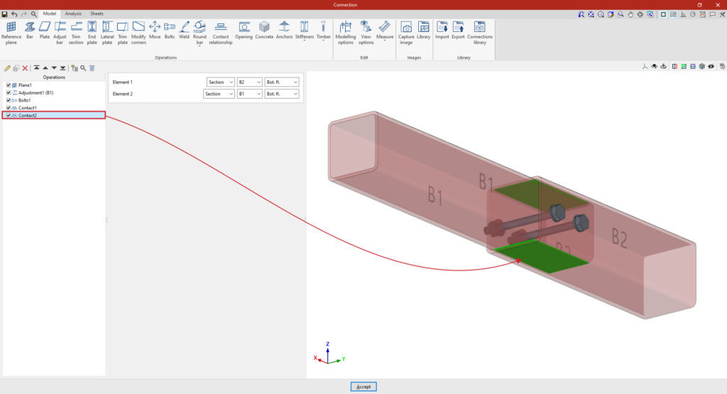
| In the example shown here, two tubular bars with different cross-sections have been defined, adjusted so that one is embedded inside the other. Next, the contact relationships between the surfaces of both bars are defined: 1. In the first step, the contact between the “Top flange” of both sections is defined using the various drop-down menus available. 2. You can then copy this operation and, whilst retaining the rest of the data, select the “Bottom flange” of both sections to define their contact. Once the model is complete, you can continue by opening the “Analysis” tab to perform the analysis of the connection. |
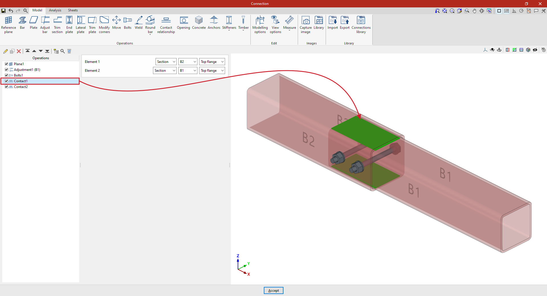
Contact surfaces between two steel profiles
Contact with concrete surfaces
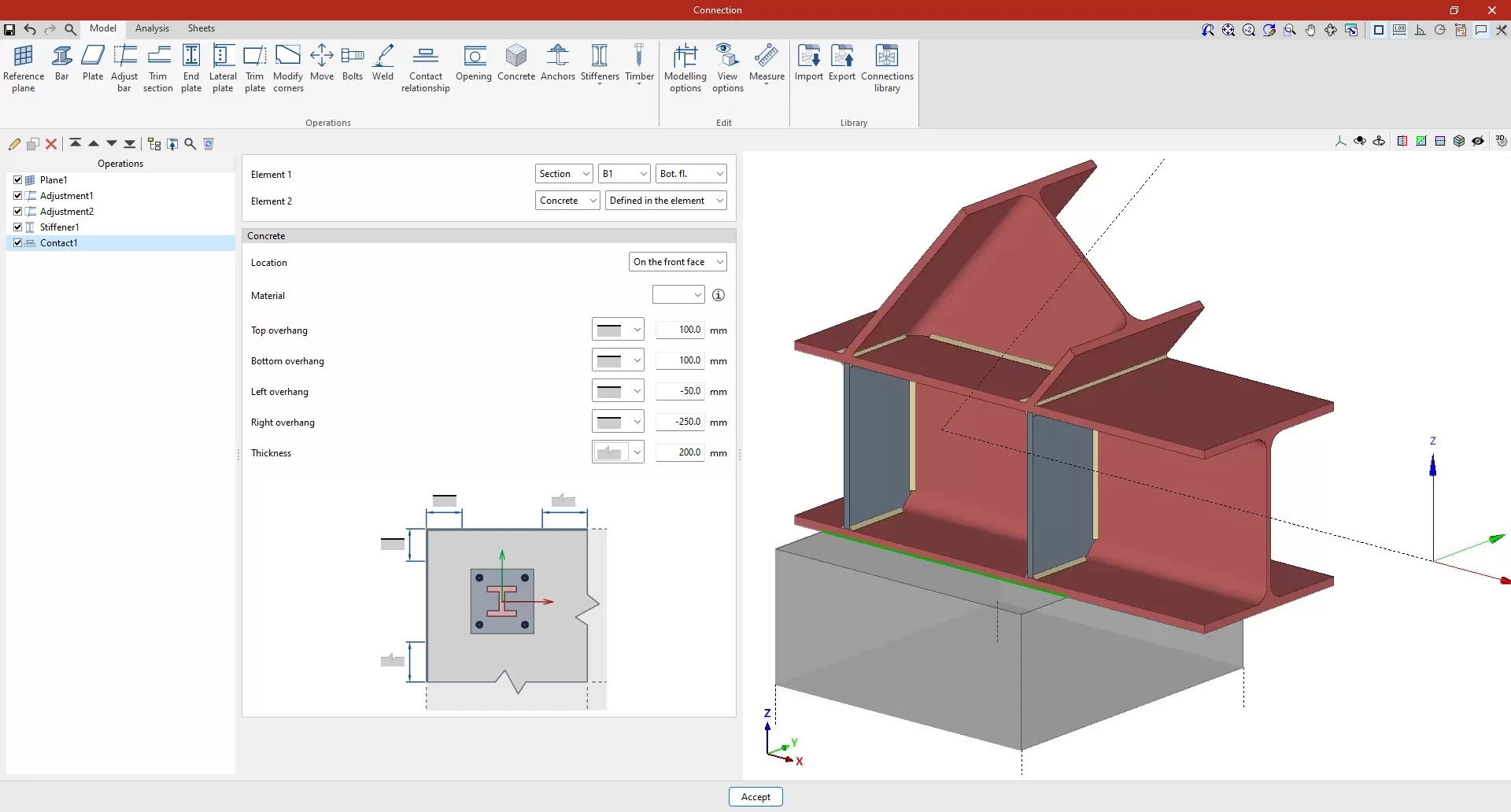
You can define a contact between a steel surface and the surface of a concrete element. To do this, select “Concrete” in the “Element 2” section.
The concrete element can be a new element defined in this operation, if "Defined in the element" is selected, or an existing element, in which case "Selection" must be chosen.
If "Defined in the element" is selected, the following parameters must be specified:
- The "Location" of the concrete element, whether "On the front face" or "On the back face" of the contact interface
- The element’s “Material”, which can be selected from those available
- The geometry of the element, defined by the values for "Top overhang", "Bottom overhang", "Left overhang", "Right overhang" and "Thickness", measured from the contour of the contact surface. For each of these, you must indicate whether or not the concrete element extends beyond the specified values by selecting the corresponding option from the drop-down menu.