
Obtaining reports
CYPECAD reports provide the information required to complete the project, including all the data entered in the model, the analysis results, and the measurements and quantities of the structure.
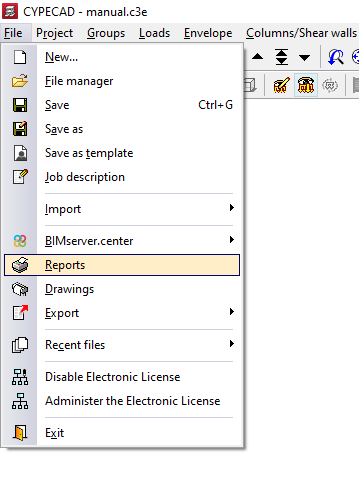
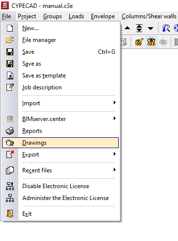
To access the reports, open the "File" menu and select the "Reports" option. Alternatively, reports can be accessed using the "Reports" button available in the upper right-hand part of the program interface.
Report selection
The program displays all the available reports on screen:
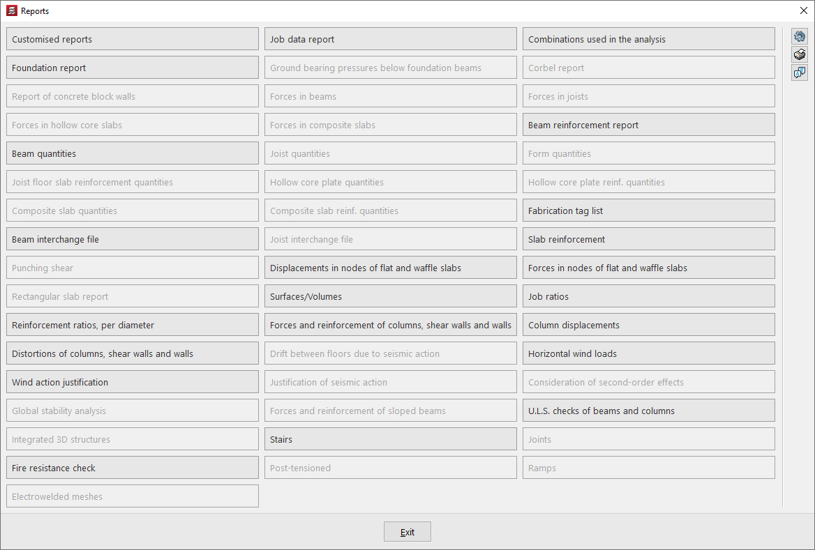
In addition, the options explained below appear on the right-hand side.
Report options
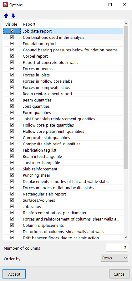
With the first button on the right, "Options", it is possible to enable or disable the visibility of the different reports in the previous "Reports" panel, as well as modify the order in which they are displayed, specify the "Number of columns", and "Sort by" "Rows" or "Columns".
View all possible reports in the project
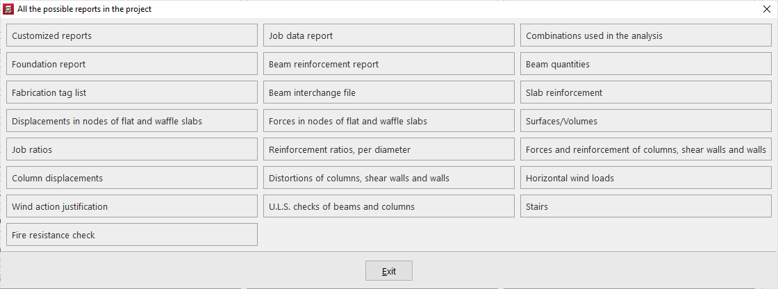
Some reports can be consulted before the analysis is carried out, while others require the project to be analysed. In addition, not all reports will be available in all projects, as some refer to specific elements and analyses.
It is possible to view "All possible reports in the project" by clicking the corresponding button on the right-hand side of the report selection window.
Language for reports and drawings
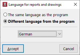
Using the "Language for reports and drawings" option, also accessible on the right-hand side of the "Reports" window, it is possible to select a language other than that of the program installation for generating reports and drawings. The following options are available:
- The same language as the program
The language of the documents will be the same as that used in the program installation. - Different language from the program
The language of the documents will be the one selected from those available in the drop-down list.
| Note: |
|---|
| References to certain project elements (such as, for example, the names of groups and storeys) will appear in the language in which they were entered. The same applies to general program settings, such as the names of "Floor plans", or the chapters of "Custom reports". |
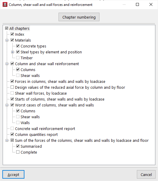
Chapter selection
When selecting a report, a window may appear in which it is possible to select the chapters, the groups, or the type of elements and information to be included in the report.
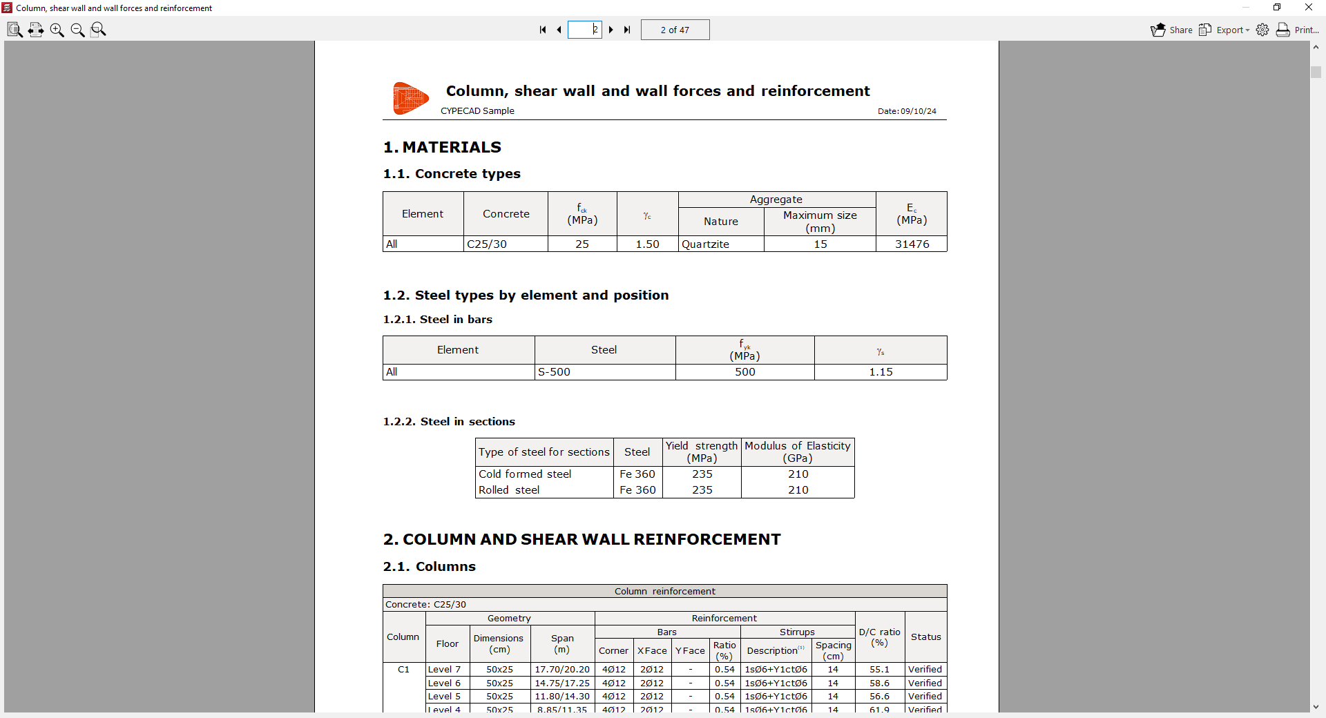
Report preview
After accepting the previous windows, an on-screen preview of the report is obtained, where the information it contains and the pagination can be consulted.
From this preview, the information can be "Exported" in different formats such as PDF, DOCX, text (TXT), HTML and RTF.
The report can also be "Shared" by generating a private link, which can be useful for showing the information to other users.
Further to the right, the "Print setup" can be carried out, where the printer to be used is selected and the "Scale" and "Margins" are defined.
Finally, by clicking "Print", the document print dialogue opens, where the "Pages to print" and other "Print data" are defined.
Obtaining drawings
CYPECAD drawings detail all the elements entered in the model and make it possible to obtain the information in different formats to complete a project.
To access drawing printing, open the "File" menu and select the "Drawings" option, or click directly on the "Drawings" button available in the upper right-hand part of the program interface. This provides access to the "Drawing selection" window.
Drawing selection
The "Drawing selection" window allows management of the list of drawings for the project.
The first option on the upper toolbar allows a drawing to be "Added". This opens the "Drawing editing" window, where the desired drawing is chosen and configured.
After accepting the "Drawing editing" window, the drawing is added to the list in the "Drawing selection" window. This process must be repeated to add all the desired drawings to the project.
At the top, the program offers the following features:
- tools to "Edit", "Copy", "Delete" and move drawings within the list,
- the options "Export drawing series", "Import drawing series" and "Delete drawing series", which allow the list of drawings entered and their configuration to be saved to disk;
- and, finally, the "Language for reports and drawings" option, which allows a language other than that used in the program installation to be selected when generating reports and drawings.
The list of drawings is organised as a table with different columns, which work as follows:
- The program will print the drawings that have the "Draw" checkbox enabled.
- If desired, the "Editing resources" entered can be included in the drawing.
- The "Drawing type" column indicates the type of drawing selected.
- By enabling the "With textbox" checkbox, a frame will be added to the drawing indicating the drawing type and its scale.
- Further to the right, the "Peripheral" is selected. Drawings can be exported in DWG or DXF format or printed directly using graphic devices and printers configurable in the program, including export to PDF.
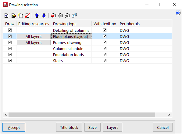
At the bottom of the window, a series of additional options is shown:
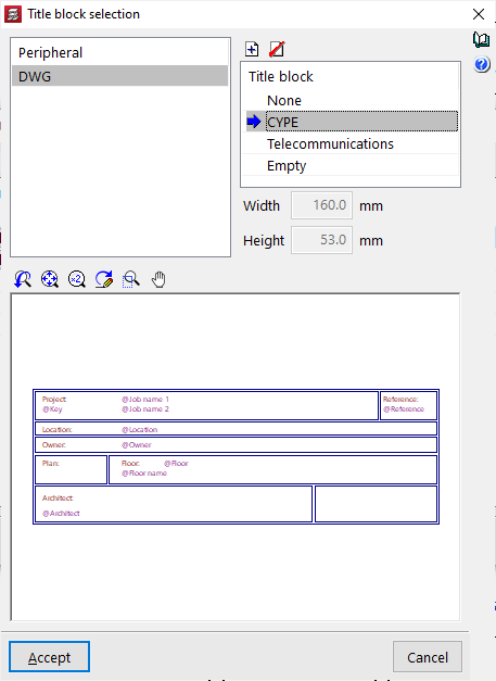
- With the "Title block" option, it is possible to import a title block from a .dwg or .dxf file, use a predefined title block, or reserve a "Blank" space in the drawing in order to add the title block manually later in another drawing program.
- The "Save" option allows the selected drawings to be saved and the window to be closed without generating the drawings.
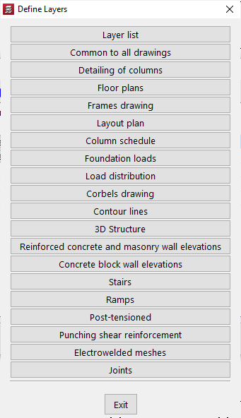
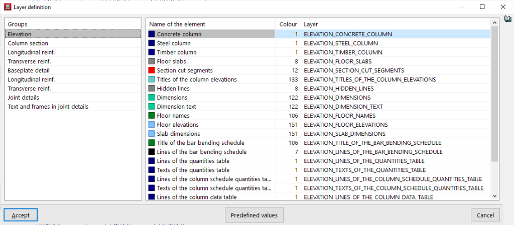
- From "Layers", the name and colour number of the layers generated in all types of drawing can be consulted and modified. The colour number may be associated with a different colour in each drawing program.
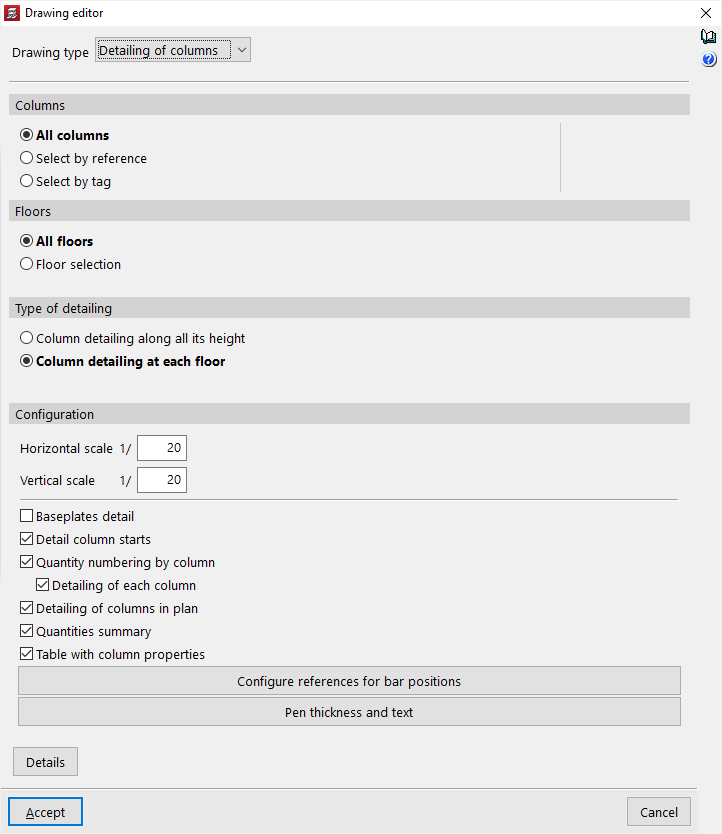
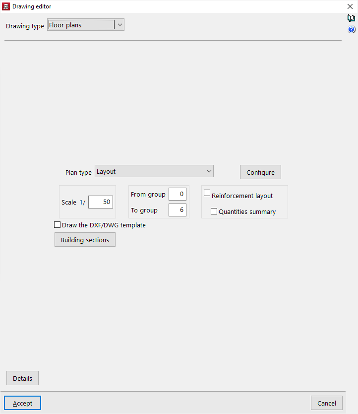
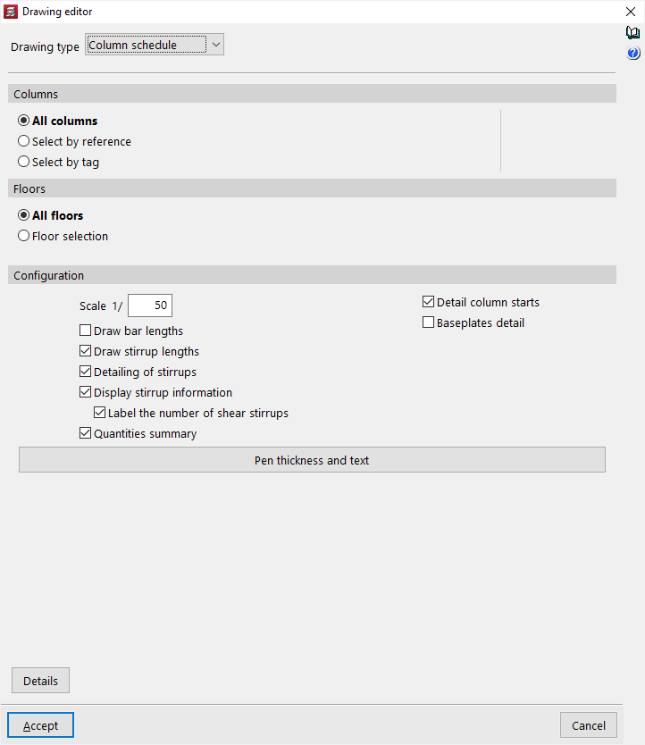
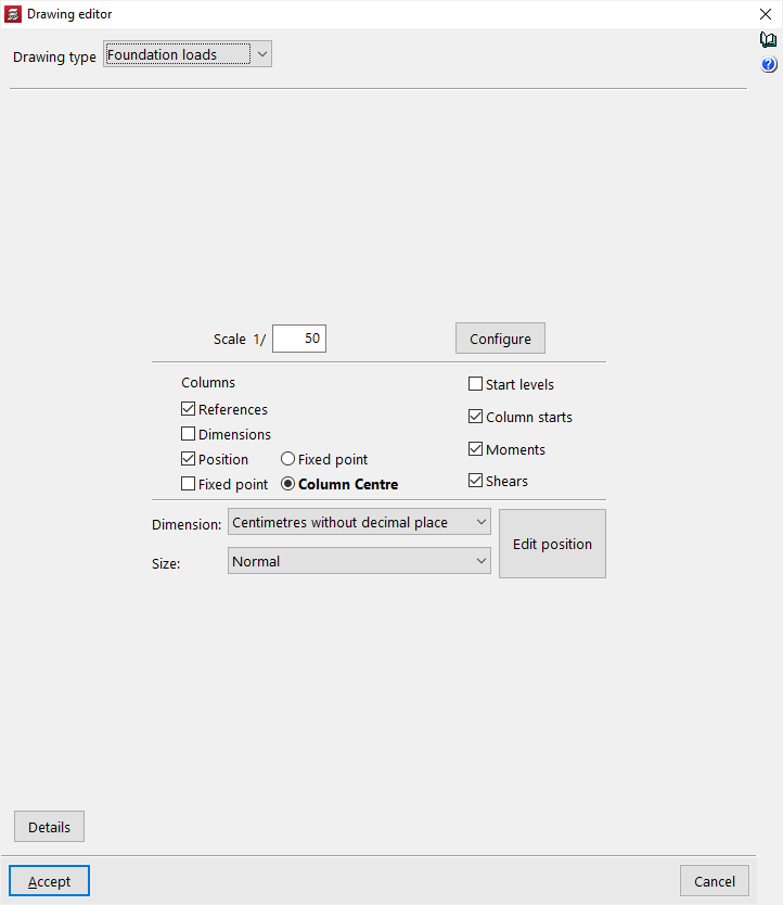
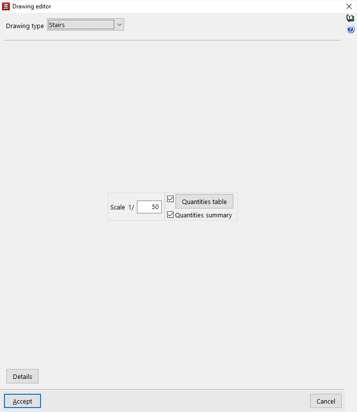
Drawing editing
The "Drawing editing" window allows the desired drawing to be selected and its configuration adjusted, and appears when adding a new drawing or editing an existing one from the "Drawing selection" window.
Within this window, in the first drop-down list, the "Drawing type" is selected. Among the available types are the following:
- Column detailing
- Floor plans
- Frame drawings
- Setting-out drawing
- Column schedule
- Loads to foundations
- Load plan
- Short corbel drawing
- Contour plots
- Elevation of reinforced concrete and masonry walls
- Stairs
- 3D structures
| Note: |
|---|
| The project must be analysed for all the drawings that the program is capable of generating with the model information to be available. |
In the central area, different detailed configuration options are shown, where it is possible to adjust the visibility of the various elements, the selection of groups to be printed, the drawing scale, or the size of pens and texts.
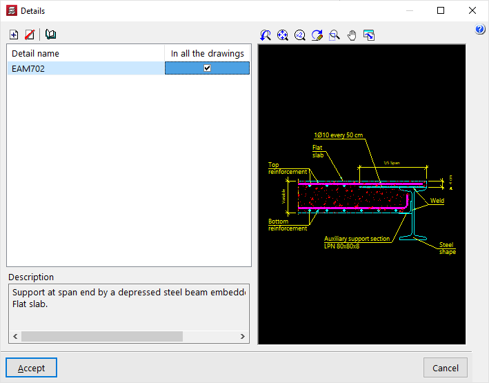
Details
Optionally, construction details can be added to the drawing. To do this, click on "Details" at the bottom.
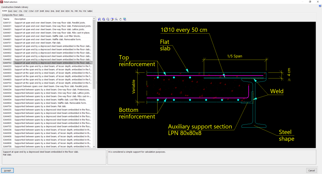
In the window of the same name, by clicking on "Add", it is possible to access the program’s "Construction detail library", where all the available details are shown organised into different tabs. After selecting a detail, click on "Accept" to add it to the drawing. It must be indicated whether the detail is shown "In all drawings" or not.
It is also possible to "Add a user detail" by creating a custom detail library and loading DXF or DWG files saved on disk into it.
After clicking "Accept", the program returns to the "Drawing editing" tab.
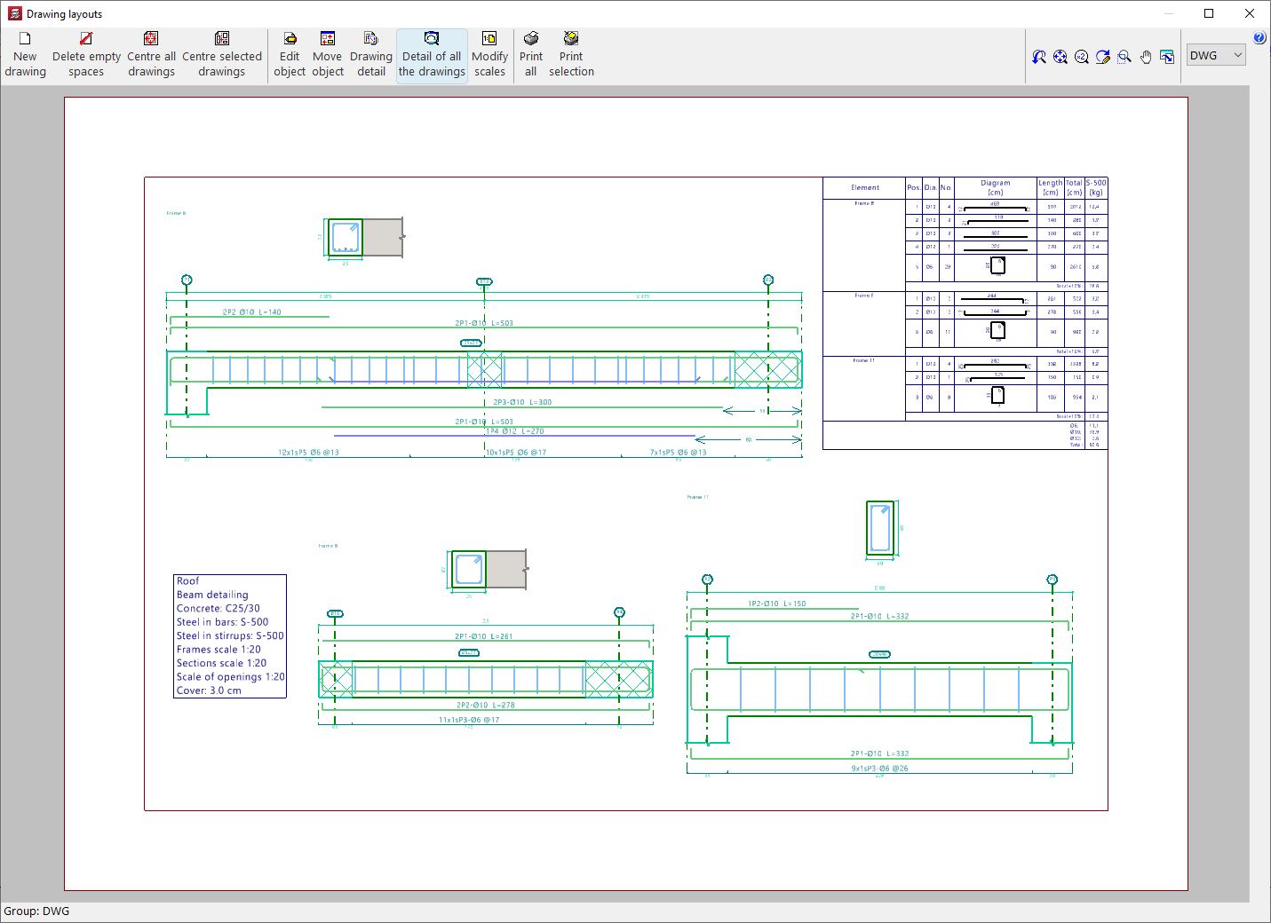
Drawing composition and printing
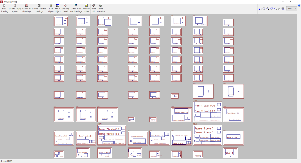
Once all the desired drawings have been loaded into the list, accepting the "Drawing selection" window opens the "Drawing composition" window, where a preview of the drawings to be generated and the drawings they contain is provided.
In this window, some limited operations can be carried out:
- New drawing
Creates a new drawing by choosing its format. - Delete blanks
Deletes empty drawings that contain no drawings. - Centre all drawings
Restores the original position of the drawings on all drawings. - Centre selected drawings
Restores the original position of the drawings on the selected drawings. - Edit drawing
Moves elements (such as texts) within each drawing. - Move drawing
Moves the selected drawings to change their position or place them on different drawings. - Modify scales
Allows the scale of some types of drawing to be modified (for example, floor plans).
The drawings placed on the sheets are shown without detail so that the computer consumes fewer resources and allows the above operations to be carried out more quickly. If it is desired to see the detailed content of the drawings, the following options are used:
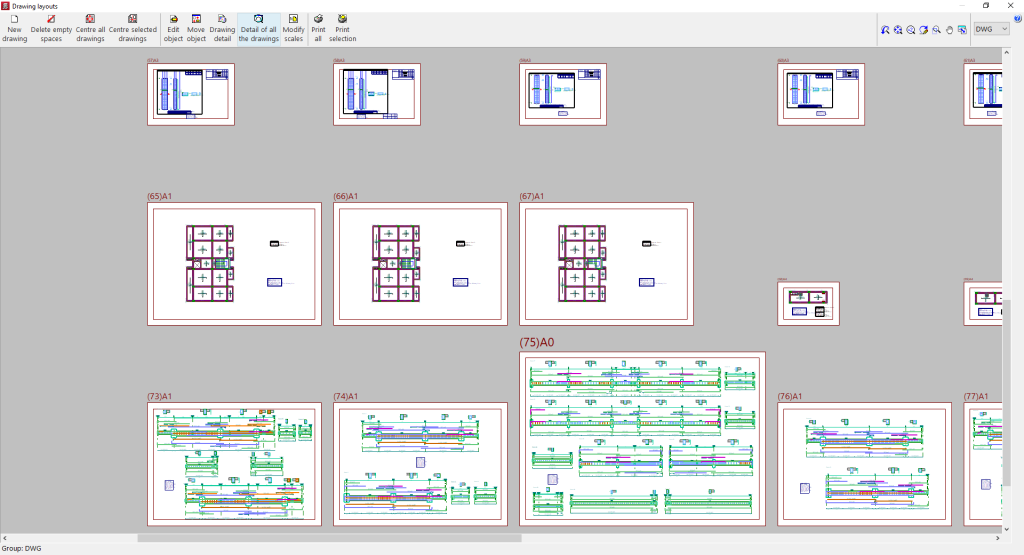
- Drawing detail
Shows the detailed information contained in the selected drawing. - Detail of all drawings
Shows the detailed information contained in all drawings.
Finally, to print the drawings, the following options are available:
- Print all
Prints all drawings. - Print selected
Prints only the selected drawings.
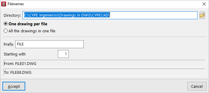
If export to .dxf or .dwg files has previously been selected, the program will ask for the "Directory" and the "File name" to be specified.
If several drawings have been selected, it is also chosen whether each drawing is included in a separate file (which will generate a set of files), or whether all drawings are generated in a single file:
- Each drawing in a file
- All drawings in a single file
Upon accepting, the drawings will be generated in the selected directory. Optionally, if only a single file is being generated, it can be "Shown with the associated program" for reading that file format.
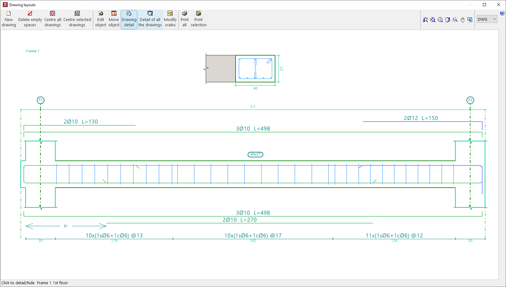
Editing the frame drawing
The frame drawing provides detailed information on the sections and reinforcement of the beams and frames of the structure. This drawing can be obtained after analysing the job.
The drawings are configured by adding or editing a drawing using the tools in the "Drawing selection" window, which appears when you use the "Drawings" option in the top toolbar or the "File" menu in the general interface.
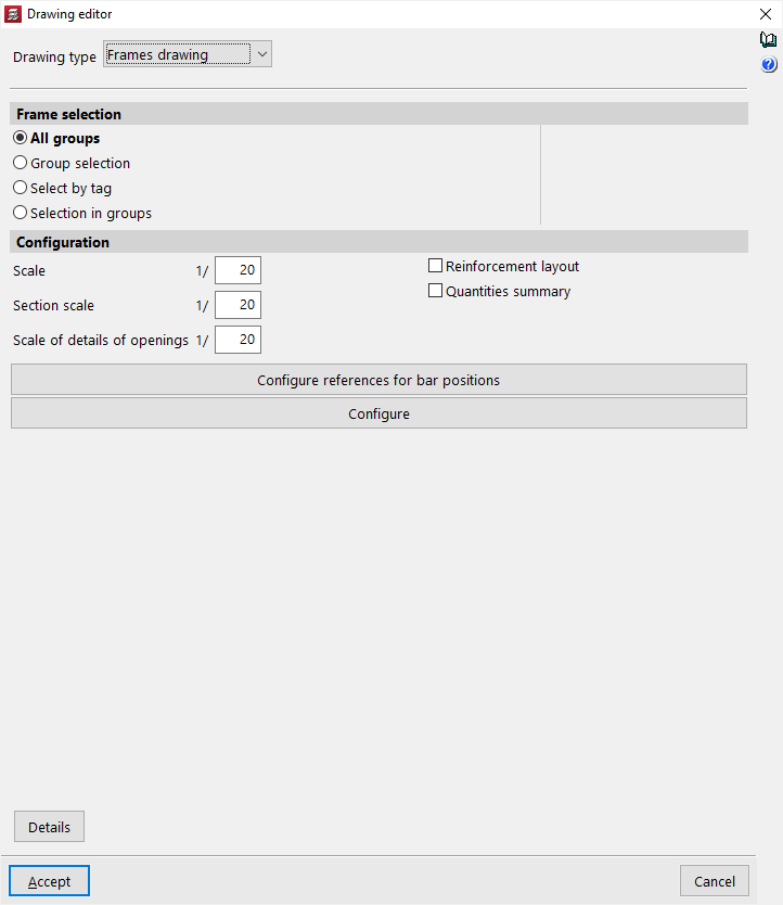
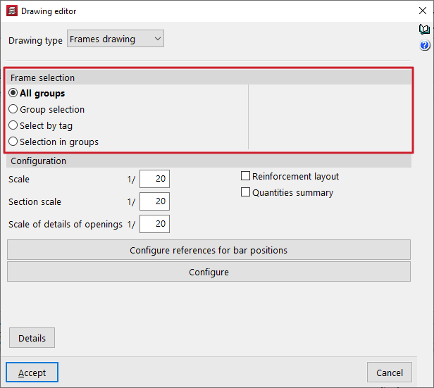
In the case of a "Frame drawing" type drawing, the editing options are as follows:
Frame selection
In this section, you can choose the frames you want to represent in the drawings. These can be:
- All groups
- Generates the frame drawings for all groups in the project.
- Group selection
- Generates the drawings for the frames located between the groups selected in the "Up to group" and "From group" drop-down menus, both included.
- Selection by tag
- Generates the drawings for the frames located between the groups selected in the drop-down menus and associated with the "Tags" indicated. Labels are managed from the "Tags" panel, within the "Groups" menu of the "Beam input" tab.
- Selection in groups
- Generates the drawings for the frames selected one by one in the "Frame selection" pop-up window.
Configuration
In this section, you can choose the frames you want to represent in the drawings. These can be:
- Scale
Defines the scale of the longitudinal section of the frames. - Section scale
Defines the scale of the cross-section of the frames. - Scale of details of openings
Defines the scale of the details of the openings in the beams. - Reinforcement layout (optional)
Checking this box adds position marks (by default, the letter P) that appear in the reinforcement texts and allow you to detail the layout of the frames' reinforcement. These position marks, accompanied by a number, reference the bar or bars on which they are located with respect to a table that the program places in the upper right corner of the drawing.
If you do not want to perform this detailed layout, do not tick this box. Even if it is not checked, you can still obtain the measurement summary. - Measurement summary (optional)
- Checking this box adds a table with a measurement summary of the reinforcement in the frames in the drawing. It includes information on the total lengths and weights for each diameter, as well as the total weight of all the reinforcement.
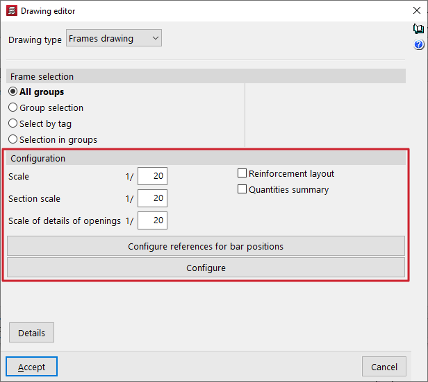
The "Configure references for bar positions" and "Configure" options can be used to make the following additional adjustments:
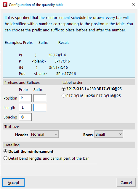
Configure references for bar positions
If the "Reinforcement detailing" box is checked to specify that the bars should be detailed, each bar is identified with a number corresponding to its position in the table. A prefix and suffix can be specified to be placed before and after this number.
These tags can be configured in the window that appears when you click on "Configure references for bar positions":
- Prefixes and suffixes
You can define the prefixes and suffixes used in the composition of the labels:- Position (Example: prefix "P", suffix "-")
- Length (Example: prefix "L=")
- Separation (Example: "@")
- Label order
You can select the order of labels from the following two schemes:- 3P17-Ø16 L=250 3P17-Ø16@25
- P17-3Ø16 L=250 P17-3Ø16@25
Meaning: 3 bars with a diameter of 16 mm in position 17, with a length of 250 mm / separated every 25 cm.
- Text size
Defines the size of the "Header" and "Rows" texts. - Detailing
In this section, you can select whether you want to "Detail the reinforcement" or "Detail bend lengths and the central part of the bar", in which case you can optionally "Indicate bend lengths".
Options in the "Configure" window
Clicking on the "Configure" button opens a window with three tabs containing different configuration options.
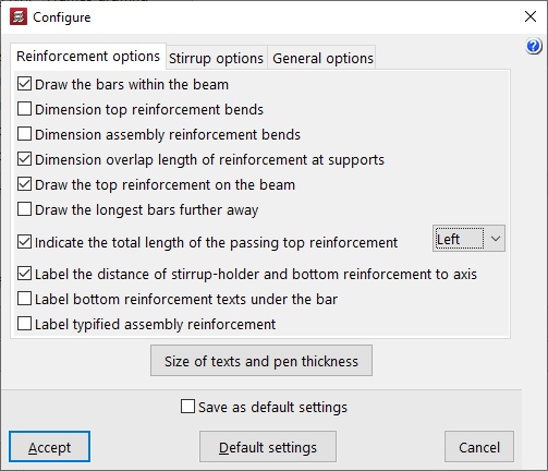
In the "Reinforcement options" tab, the program offers the following configuration options for the longitudinal reinforcement of beams:
- Draw the bars within the beam
- Dimension top reinforcement bends
- Dimension mounting reinforcement bends
- Dimension length of reinforcement overlaps at supports
- Draw the top reinforcement on the beam
- Draw the longer bars further away
- Indicate the total length of the passing top reinforcement (Left / Right / Both)
- Label the distance of stirrup-holder and bottom reinforcement to axis
- Label bottom reinforcement texts under the bar
- Label typified assembly reinforcement
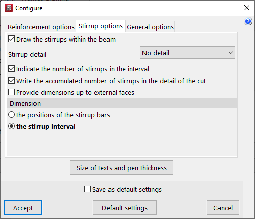
Then, in the "Stirrup options" tab, the program offers the following configuration options for the transverse reinforcement of the beams:
- Draw the stirrups within the beam
- Stirrup detail (No detail / Below the section / To the right of the section)
- Indicate the number of stirrups in the interval
- Write the accumulated number of stirrups in the detail of the cut
- Provide dimensions up to external faces
- Dimension (the positions of the stirrup bars / the stirrup interval)
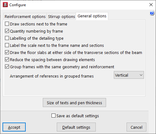
Finally, in the "General options" tab, the program offers the following general configuration options for frame drawings:
- Draw sections next to the frame
- Quantity numbering by frame
- Labelling of the detailing type
- Label the scale next to the frame name and sections
- Draw the floor slabs at either side of the transverse sections of the beam
- Reduce the spacing between the drawing elements
- Group frames with the same geometry and reinforcement
- Group frames with the same geometry and reinforcement (Horizontally / Vertically)
| Note: |
|---|
| To optimise the space used in the drawings, you can place the "Stirrup detail > To the right of the section" (instead of "Below the section") and check the "Reduce the spacing between drawing elements" option. This allows you to compact the drawing elements and even reduce the number of sheets needed to accommodate the drawings for the selected frames. |
Integration into the BIMserver.center platform
Many of CYPE's programs are connected to the BIMserver.center platform and allow collaborative work to be carried out via the exchange of files in formats based on open standards.
Please note that, to work on BIMserver.center, users can register on the platform free of charge and create a profile.
When accessing a program connected to the platform, the program connects to a project in BIMserver.center. This way, the files of the projects that have been developed collaboratively in BIMserver.center are kept up to date.

| More information: |
|---|
| For further details related to using CYPE software via the BIMserver.center platform, please click on this link. |
Options available in CYPECAD
The link between CYPECAD and the BIMserver.center platform integrates this program into a collaborative and multidisciplinary workflow that allows the development of projects in an open, coordinated and simultaneous manner between the different specialists involved.
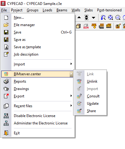
The link to BIMserver.center can be made when creating a new job in CYPECAD or by using the "BIMserver.center" menu available in the "File" menu, as well as in the upper right-hand side of the program interface, which has the following options:
- Link
- Unlink
- Import
- Consult
- Update
- Share
Details of the above-mentioned features are given below:
Linking (creating a new job)
The link with BIMserver.center can be made when creating a new job. To do this, select the "New" option from the "File" menu and enter the file name and its description.
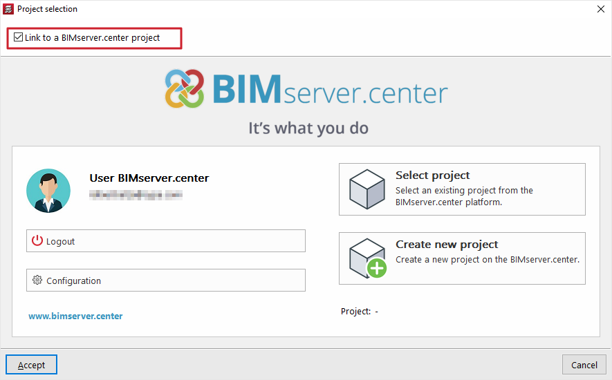
After accepting, in the next window there is the possibility to link to a BIMserver.center project by ticking the corresponding checkbox.
By clicking on the "Select project" option and choosing a project that contains information that can be imported by CYPECAD, the "Import BIM models" wizard opens, allowing you to transform the elements read into native CYPECAD elements.
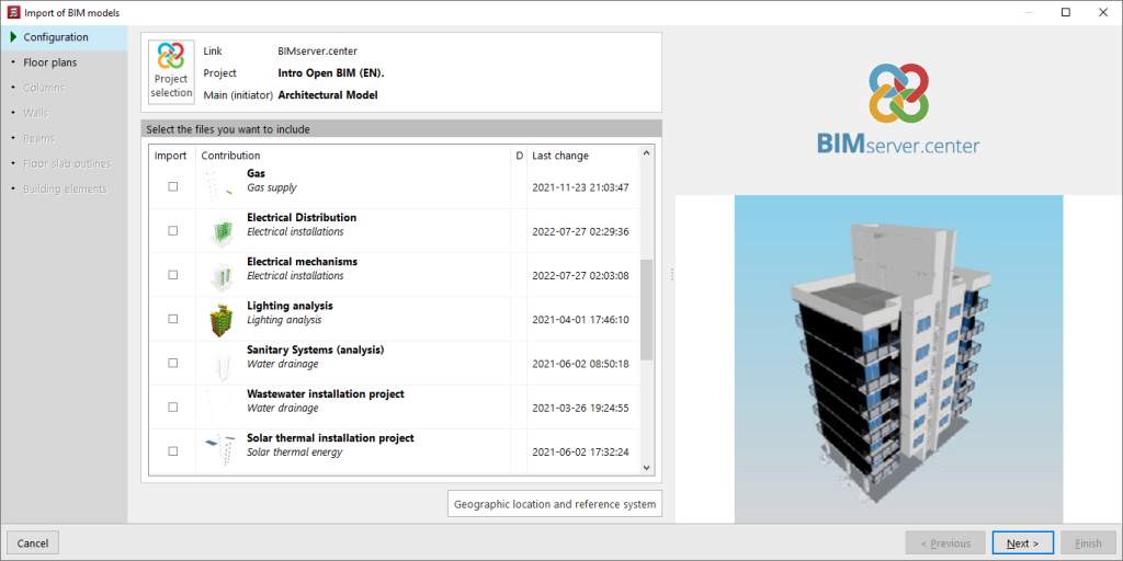
Automatic BIM model import wizard
In "Configuration", the program shows which is the main or initiator file, corresponding to the architectural model, in the upper part. In the lower part, files from other disciplines which are to be included can be selected.
In the following sections, "Floor plans", "Columns", "Walls", "Beams", "Floor slab outline" and "Building elements", the automatic import of these into the design model is configured, if necessary.
Linking ("BIMserver.center" menu)
A CYPECAD job can be linked to BIMserver.center after it has been created. To do this, from the "Beam definition" tab or the "Results" tab, open the "BIMserver.center" menu on the top right. Then select "Link".
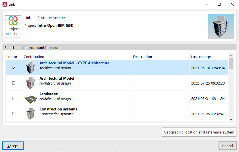
In the next window, click on "Project selection" and then select the BIMserver.center project where the model information is hosted. There is also the option of creating a new project, in case it has not been created before.
After accepting, the files from other applications and disciplines to be included are selected at the bottom by checking the boxes in the "Import" column. By accepting, the linking is completed.
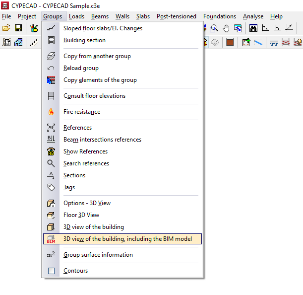
The information contained in the above-mentioned files will be visible in the "Groups" menu of the "Beam definition" tab using the "3D view of the building, including the BIM model" option.
From the "Elements" menu at the top left, different files of the BIM model can be activated or deactivated. This display will help in the process of geometric definition of the elements of the structure.
| Note: |
|---|
| The "Link" option does not allow access to the automatic BIM model import wizard, so the information read will not be automatically transformed into CYPECAD native elements. To achieve this, the "Import" option in the same menu must be used. |
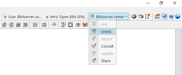
Unlink
From the "BIMserver.center" menu it is also possible to "Unlink" the job from the BIM project. The job can be linked to the same or any other project at any time.
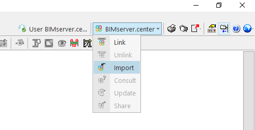
Import
The "Import" option is used to read the architectural model of the BIMserver.centre project and to transform it into native CYPECAD elements, as well as linking the job to a BIMserver.center project.
This generates the floor plans, columns, load-bearing walls, beams, floor slab outlines and building elements in the design model, using the same BIM model import wizard that appears in the process of creating a new job.
| Note: |
|---|
| This option is only available when no new floors have been created in CYPECAD. |
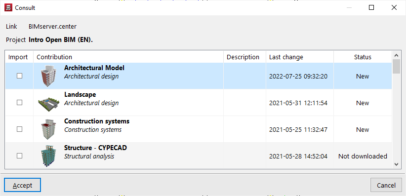
Consult
The "Consult" option is used to consult the status of the files included in the BIMserver.center project. On the right-hand side, the program indicates whether they have undergone changes. To include the files with the changes, activate the "Import" checkbox on the left-hand side and accept the window.
Update
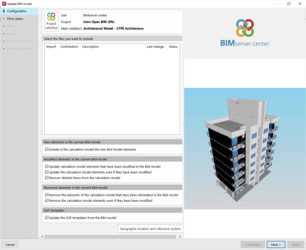
The "Update" option opens a BIM model update wizard.
In the first section of the wizard, "Configuration", the program allows new elements to be included in the design model, modified elements to be updated or deleted elements to be deleted through a series of checkboxes that can be activated or deactivated.
In addition, the "DXF templates" included in the BIM model can be updated.
At the bottom, files from other applications and disciplines are selected to update their information.
In the following sections of the wizard, the changes in the "Floor plans", "Walls", "‘Beams", "Floor slab outline" and "Building elements" can be collected. After clicking on "Finish", the program displays a window with the "Update results", indicating the processed, created, modified and deleted elements, as well as possible incidents.
Share
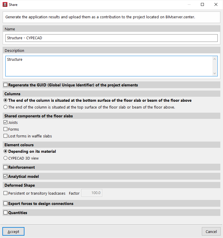
The "Share" option allows the information from the CYPECAD model to be dumped into the BIMserver.center project.
To do this, first enter the name of the file to be exported and its description.
If the "Regenerate the GUID (Global Unique Identifier) of the project elements" option is activated, new identifiers are generated for the structural elements, so that they are considered as new elements in the project.
In the "Columns" section, a choice is made between "The end of the column is situated at the bottom surface of the floor slab or beam of the floor above", or "The end of the column is situated at the top surface of the floor slab or beam of the floor above".
In the "Shared components of the floor slabs" section, "Joists" can be activated if the export of joists is desired, with or without "Lattices of the reinforced joists", the "Forms" or the "Lost forms in waffle slabs", depending on the case.
In the next section, "Element colours" can be defined as "According to their material" or the colours used in the CYPECAD 3D view can be selected with the "CYPECAD 3D view" option.
The geometry of the reinforcement, the analytical model and the deformed shape can also be exported by checking the corresponding options and indicating a scale factor for the different loads.
| Note: |
|---|
| To convert reinforcement steel (generated in CYPECAD) to native Revit entities using the Open BIM Plugin - Revit plugin, you must check the following boxes: "Reinforcement" + "One IFC file with all the floors" and/or "One IFC file per floor" + "Include the description of the bars in BVBS format in the IFC files". For more information, please refer to this link. |
If necessary, the "Export forces to design connections" option can be checked in order to export them to other programs such as CYPE Connect or StruBIM Steel.
The last boxes allow the export of the quantities and the bill of quantities of the structure.
After accepting, the program will carry out the export process and display the "Information" box to indicate whether it has been successfully completed. By accepting again, the information will be uploaded to the BIMserver.center project, allowing the project participants to view it in the linked applications.
This information will also be visible in the corresponding project section on the BIMserver.center website.
Table of contents
Complete your tour of CYPECAD by exploring the other available sections:
- Introduction
- Introduction and creating new jobs
- General data configuration
- Defining floors and groups of floors and inserting columns, shear walls and starts ("Column input" tab)
- Inserting beams, walls, floor slabs, foundation elements and special elements, and structural analysis (the "Beam Input" tab):
- Checking analysis results and editing elements (the "Results" tab):
- Options on the "Contour plots" tab
- Printing documents and exporting data
- More information:
- General features of CYPECAD