
Code configuration
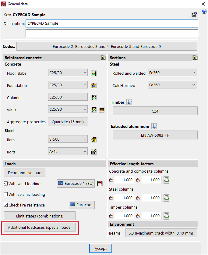
In CYPECAD, settings are configured via the "Project" menu by selecting the "General Data" option. This menu can be accessed from the various tabs within the program. The general data settings also appear automatically when creating a new project.
Key, description and comments
At the top of the window, the program allows you to view the "Key" or the file name and enter a "Description".
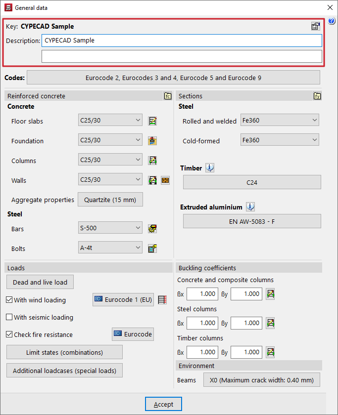
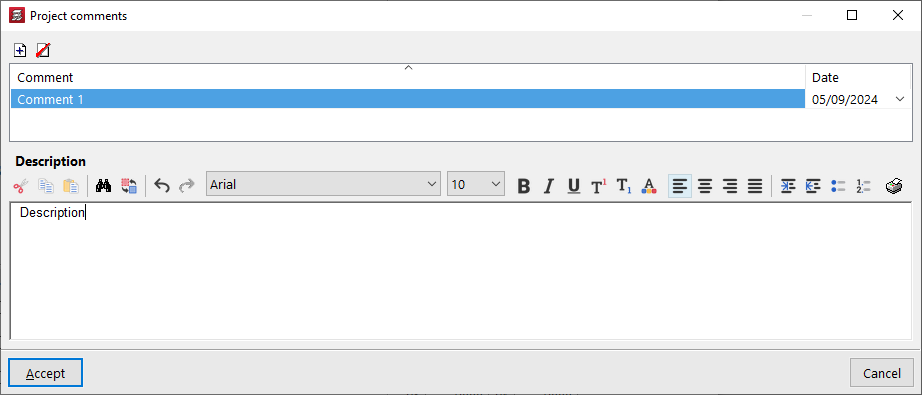
On the right, the "Project comments" option takes you to a comments management table where you can add any notes about the project that you consider relevant, linking them to a "Date".
Selection of standards
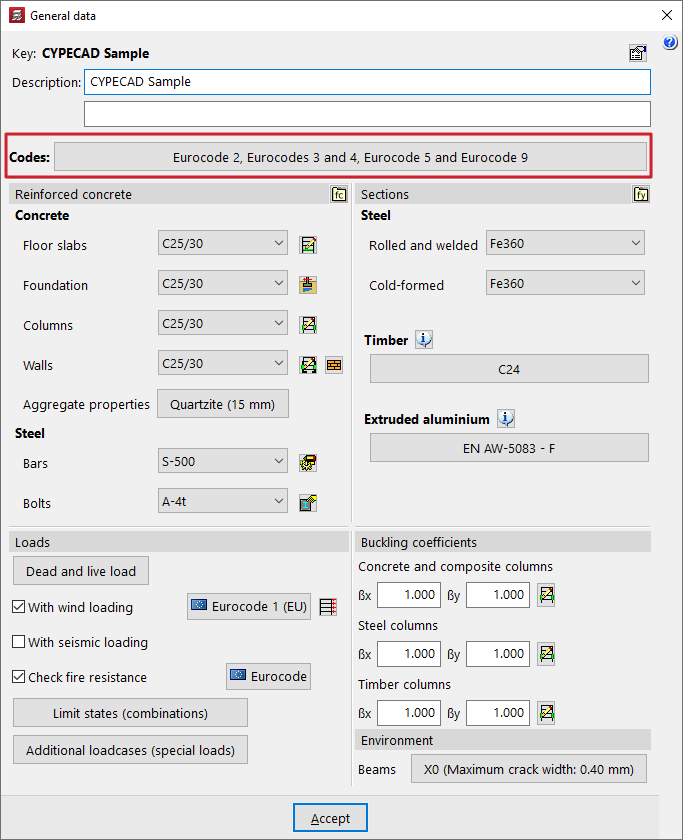
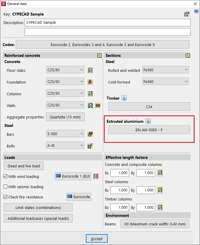
The project's "Codes" are defined by clicking on the relevant button in the "General data" window.
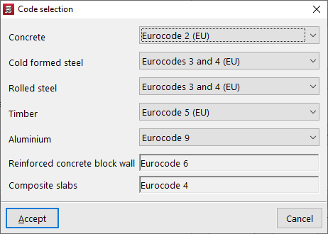
This brings up the "Code selection" window, where you can select the standards associated with elements made from the following materials:
- Concrete
- Cold formed steel
- Rolled steel
- Timber
- Aluminium
- Reinforced concrete block wall
- Composite slabs
For each one, select the required code from those available in the drop-down menu.
| More information: |
|---|
| The standards covered by CYPE’s programs can be viewed via this link. |
Reinforced concrete configuration
The configuration of reinforced concrete used in elements of this material in CYPECAD is carried out in the "Project" menu by selecting the "General data" option. This menu can be accessed from the different tabs in the program. It also appears automatically when creating a new project.
Options in the "Reinforced concrete" section
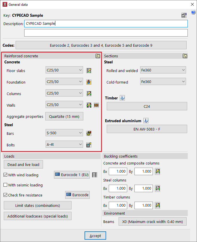
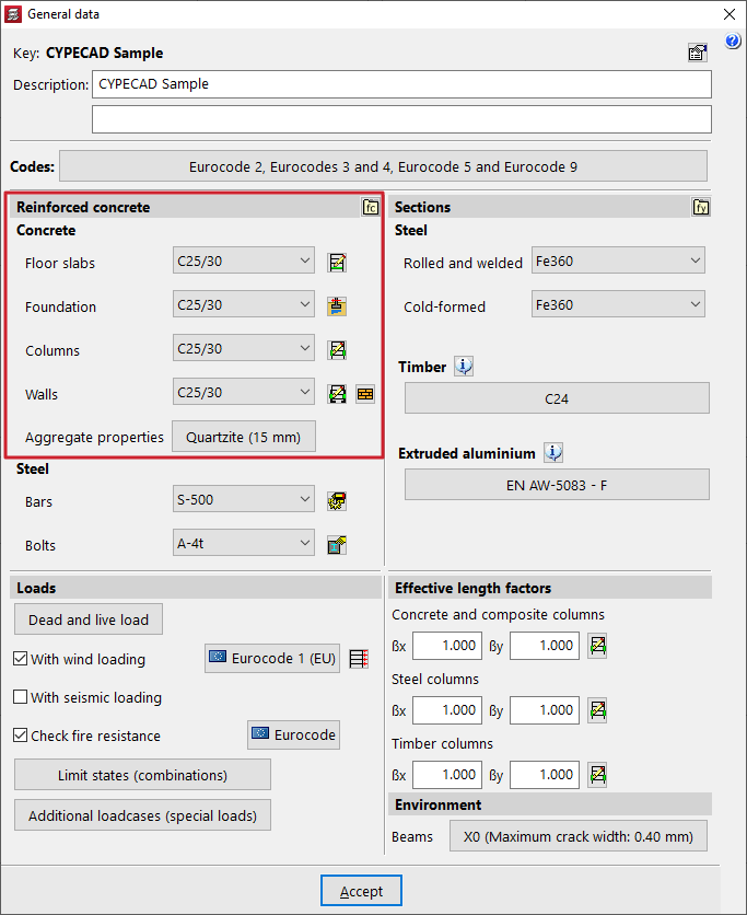
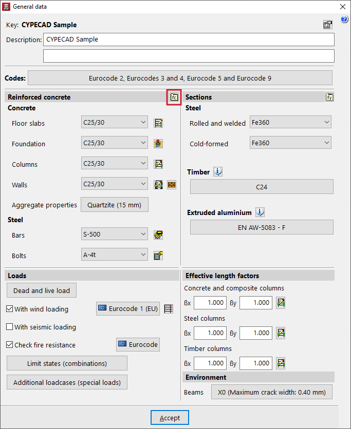
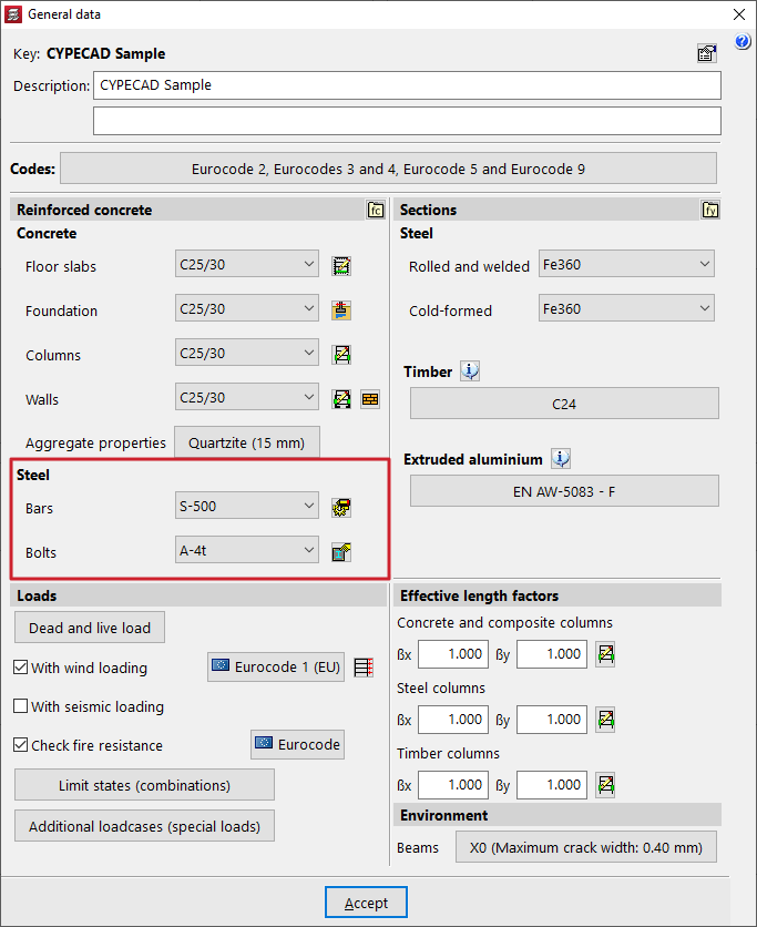
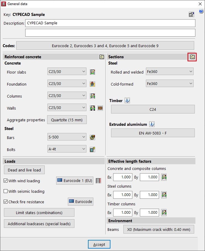
Within the "General data" window, the project materials are defined in the "Reinforced concrete" and "Section" sections.
In the "Reinforced concrete" section, both the "Concrete" and the "Steel" for reinforcement and bolts are configured.
Each of these options is detailed below.
Selecting concrete
The various drop-down menus in this section can be used to select the "Concrete" for the "Floors", "Foundations", "Columns" and "Walls".
The materials that appear as default in the various drop-down menus correspond to those covered by the previously selected standards.
| Note: |
|---|
| The concrete defined in the "Floor slabs" drop-down menu will also be applied to beams, sloping beams, stairs, and concrete elements in integrated 3D structures. |
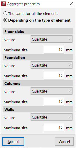
The corresponding section allows you to modify the "Aggregate properties". These can be "The same for all elements" or "Depending on the type of element".
In any case, you can indicate the "Nature" of the aggregate in the drop-down menu, as well as the "Maximum size" of the aggregate.
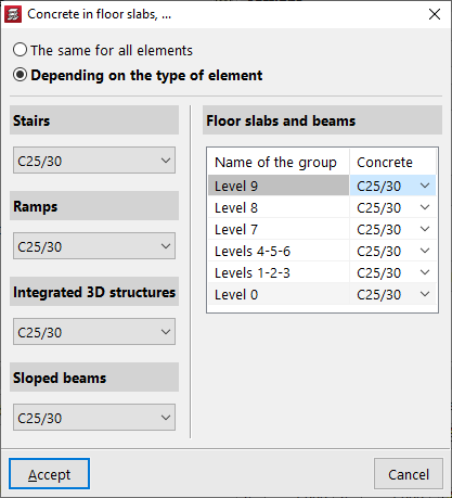
If the project has more than one group, you can click the "By group" button to the right of the "Slabs" drop-down list to select "The same (concrete) for all elements" or "By type".
In the latter case, a different concrete grade can be specified for "Stairs", "Ramps", "Integrated 3D structures" and "Sloping beams".
For slabs and beams, the table on the right-hand side allows a different concrete grade to be defined depending on the group in which they are located.
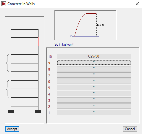
To the right of the "Columns" and "Walls" drop-down lists, the "By floor" button allows the concrete grade assigned to column or wall segments to be defined on a floor-by-floor basis.

User concrete
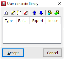
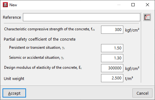
If necessary, you can define a user concrete from the "User concrete library" option and, after clicking on "New", specify its properties.
These include the following:
- Reference
- Characteristic compressive strength of concrete
- Partial safety factors for concrete
Defined for persistent or transient situations and for seismic or accidental situations. - Design modulus of elasticity of concrete
- Unit weight
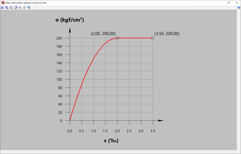
You can also consult the "Concrete stress-strain diagram" using the corresponding option on the right.
User concretes can be exported and imported into other projects. After creating a user concrete, it can be selected from any of the drop-down menus mentioned above.
Selection of reinforcing steel and bolt steel
The reinforcing steel for concrete elements and the steel for bolts is defined in the drop-down menus for the "Bars" and "Bolts" options.
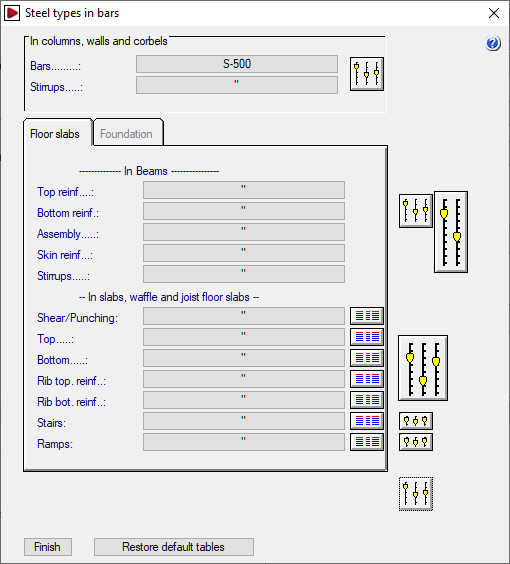
To the right of the "Bars" drop-down menu, the "By position" button allows you to access the "Steel types in bars" window, where you can assign different types of steel depending on their position in the different elements of the structure.
In addition, using the options on the right, you can edit the reinforcement tables and adjust multiple analysis and design options for the reinforcement of each type of element.
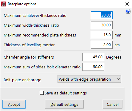
To the right of the "Bolts" drop-down menu, there is a button that allows you to adjust the "Baseplate options", which include the following.
- Relación máxima vuelo-espesor
Este dato se emplea en el dimensionamiento de la placa de anclaje. El espesor será mayor o igual que el valor del cociente vuelo máximo/relación máxima vuelo-espesor. - Relación máxima ancho-espesor
Este dato se emplea en el dimensionamiento de la placa de anclaje. El espesor de la placa será mayor o igual que el valor del cociente ancho máximo/relación máxima ancho-espesor. - Espesor máximo recomendable para placas
Si en el proceso de dimensionamiento es necesario aumentar el espesor por encima del espesor máximo recomendable para placas definido en esta opción, se emplearán rigidizadores. Este valor se puede superar cuando no sea posible emplear rigidizadores, o bien estos no sean suficientes para que la placa cumpla las comprobaciones. - Espesor del mortero de nivelación
- Ángulo en bisel para rigidizadores
- Relación máxima suma de lados-diámetro de pernos
Este parámetro se emplea en el dimensionamiento de los pernos de la placa de anclaje. El diámetro nominal de los mismos debe ser mayor o igual que el valor del cociente (lado X + lado Y) / relación máxima suma de lados-diámetro de pernos. - Anclaje pernos-placa
Checking the reinforcement layout in piles according to CIRSOC 103
The check of the reinforcement layout according to CIRSOC 103 in piles is configured as follows:
- in CYPECAD, in the "General data" window, under the "Foundation elements with external connection" button, next to the "Foundation" drop-down menu in the "Concrete" section;
- and in CYPE 3D, in the "Piles (reinforced concrete)" section of the "General data" window;
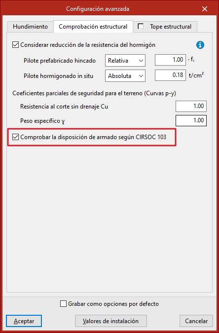
- then, in the "Piles (Reinforced concrete)" section, click on "Advanced configuration" and open the "Structural check" tab.
Here you will find the checkbox "Check the reinforcement layout according to CIRSOC 103".
If this box is checked, the specific reinforcement layout checks for piles are performed only according to the Argentine seismic standard CIRSOC 103, instead of using the criteria indicated in the concrete standard, regardless of whether seismic calculation is enabled for the project or not.
If it remains deactivated, the programme checks the reinforcement layout according to the concrete standard for compressed elements and, additionally, if seismic calculation is activated for the project, the criteria of the CIRSOC 103 standard will also be checked.
CYPECAD/CYPE 3D - Configuring and checking the structural limit in reinforced concrete piles
The structural limit or nominal load is the calculation value of the pile's resistance capacity. In the program, you can activate the structural limit check for reinforced concrete piles and check their compliance as indicated below.
Configuration in the "Structural limit" tab
The configuration tab for the "Structural limit" check can be accessed as follows:
- in CYPECAD, in the "General data" window, within the "Foundation elements with external connection" button, next to the "Foundation" drop-down menu in the "Concrete" section;
- and in CYPE 3D, in the "Piles (reinforced concrete)" section of the "General data" window;
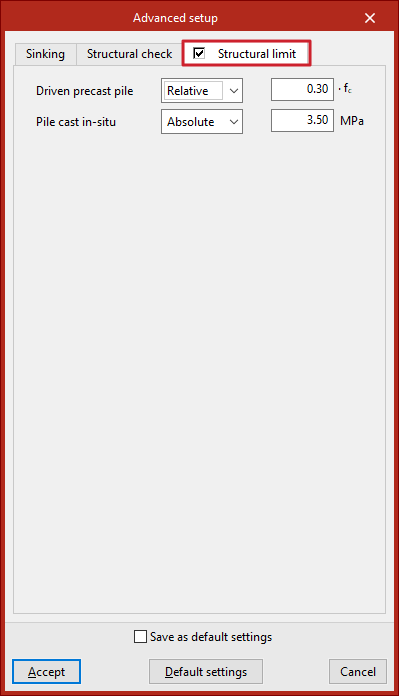
- then, in the "Piles (Reinforced concrete)" section, click on "Advanced settings".
Here, the structural stop is defined independently for "Driven precast pile" and "Pile cast in-situ".
This can be done in "Absolute" mode, by entering the structural stop value directly in pressure units, or in "Relative" mode, by entering a coefficient between 0.01 and 1 that multiplies the concrete strength (fc).
| Note: |
|---|
| The "Structural limit" tab is disabled by default in all codes except the Spanish structural code "Código Estructural". |
Structural limit check
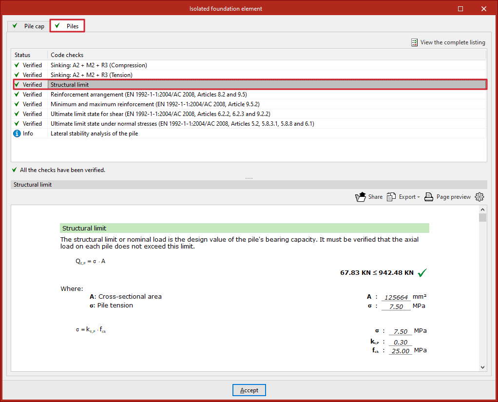
When the tab above is enabled, an additional check will appear in the check reports for each pile cap, in the "Piles" tab, indicating whether or not it complies.
For compliance, the axial stress on each pile must not exceed the defined structural limit, considering the cross-sectional area of the pile.
This is performed for the worst combination of serviceability limit states.
Configuration of materials in "Sections"
The configuration of steel, timber and aluminium section materials in CYPECAD is carried out in the "Project" menu by selecting the "General data" option. This menu can be accessed from the different tabs in the program. It also appears automatically when creating a new project.
Options in "Sections"
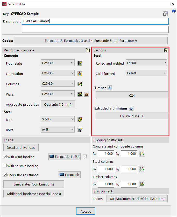
Within the "General data" window, the project materials are defined in the "Reinforced concrete" and "Sections" areas.
In "Sections", you can configure both the "Steel" of the steel sections and the "Timber" and "Extruded aluminium" of the elements made from these materials.
Selecting steel for steel sections
To define the steel for steel sections, use the drop-down menus for the options "Rolled and welded" and "Cold-formed".
Los aceros que aparecen disponibles por defecto en los desplegables corresponden con los contemplados en las normativas seleccionadas previamente.

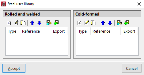
User steels
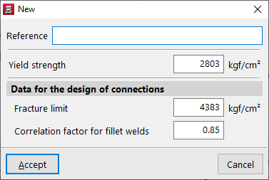
The "User steel library" option allows the user to create different types of steel, whether "Rolled and reinforced" or "Formed", by entering their details:
- Reference
- Yield strength
- Data for the design of connections
The following are included:- Fracture limit
- Correlation factor for fillet welds
After creating a user steel, it can be selected from the drop-down menus in the "General data" window.
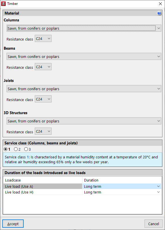
Selecting timber
The "Timber" section defines the wood used for "Columns", "Beams", "Joists" and the bars of "3D Structures" made from this material.
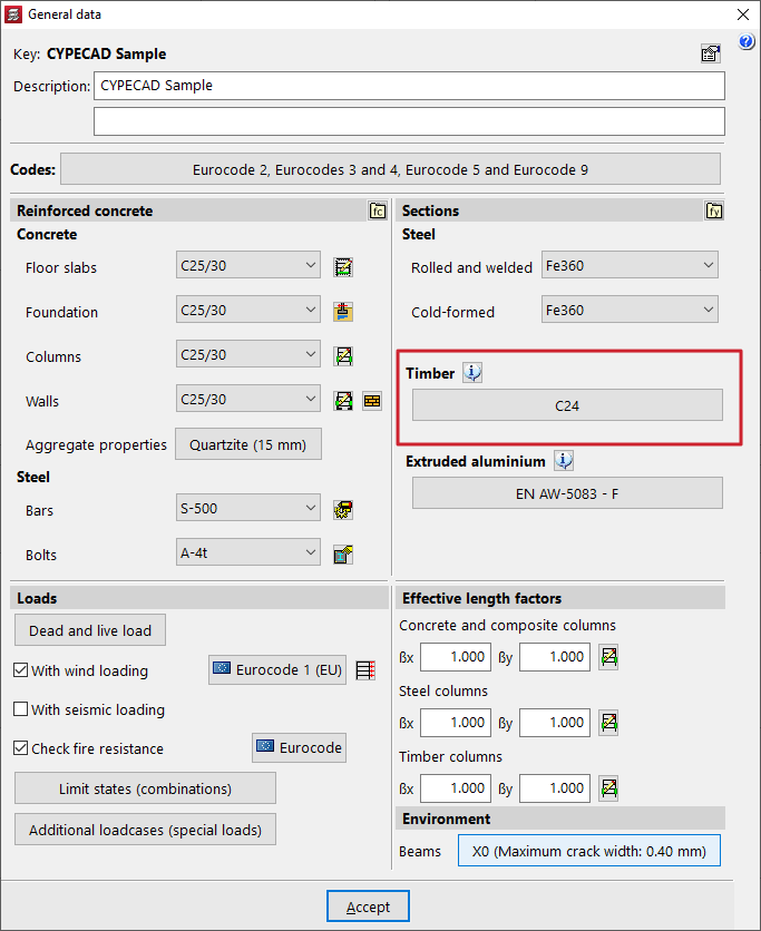
For each of these elements, the type of timber and the "Resistance class" are selected from the corresponding drop-down menus from among those available according to the chosen standard.
At the bottom, the "Service class" is defined for pillars, columns, beams and joists, as well as the "Duration of loads entered as live loads" for each "Loadcase".
| Note: |
|---|
| In the case of timber bars in integrated 3D structures, the parameters "Service class" and "Duration of loads entered as live loads" are defined independently for each integrated 3D structure. This is possible when entering timber members or by accessing the "Timber sections" option in the "Construction" tab in the editing interface. |
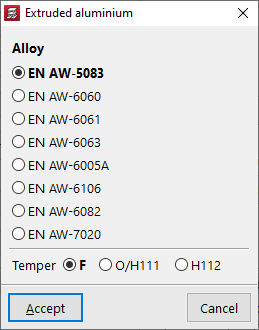
Aluminium selection
The "Extruded aluminium" section allows you to configure the material that will be applied to the aluminium elements defined in the integrated 3D structures.
In the pop-up window, you can select the "Alloy" and the "Delivery condition" from those available according to the selected standard.
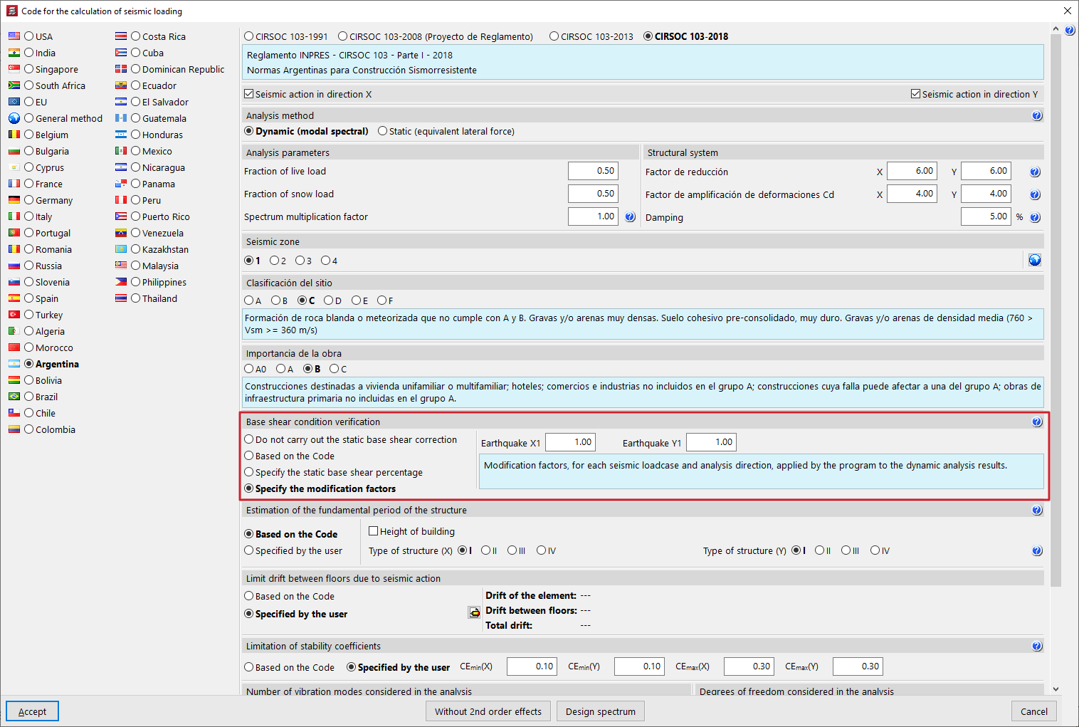
Configuration of the base shear condition verification
Some seismic codes require that the base shear resulting from the dynamic analysis exceed a certain percentage of the static shear value defined in the standard. When the dynamic shear value is lower than the minimum prescribed by the standard, the program adjusts the results by amplifying them by the corresponding modification factor.
The "Base shear condition verification" can be configured from the corresponding section of the "Regulations for seismic action calculation" window, accessible by activating the "With seismic action" checkbox in "General data".
Here, you can choose one of the following options to consider the increase in base shear forces:
- Do not carry out the static base shear correction
This option allows you to bypass the base shear check and, consequently, avoid adjusting the results. - Based on the Code
The factors calculated as specified in the selected seismic code are applied. This option only appears if the selected seismic standard considers the verification of the base shear condition. - Specify the static base shear percentage (%)
The "Percentage of static base shear" can be considered as the minimum limit in the base shear check. - Specify the modification factors
Applies modification factors to the dynamic calculation results specified by the user, according to their own considerations, seismic hypothesis and analysis direction ("Earthquake X1" "Earthquake Y1").
| Note: |
|---|
| The options that allow user criteria to be entered appear in all seismic codes, even if they do not specifically consider the verification of the base shear condition. |
Defining loadcases
Load assumptions are configured in CYPECAD in the "Project" menu by selecting the "General data" option. This menu can be accessed from the different tabs in the program. It also appears automatically when creating a new project.
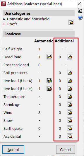
Then, at the bottom of the window, in the "Loads" section, select the "Additional loadcases (special loads)" option.
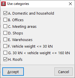
Use categories
In the "Use categories" section, all existing use categories in the project are declared within those covered by the selected standards. To do this, use the edit button and activate the desired categories (e.g. domestic and household, offices, warehouses or vehicle weight).
For the program, a use category is a group of use overload loadcases combined with the same combination coefficients as the other loadcases defined in the project. The categories are then assigned to each group via the group edit menu.
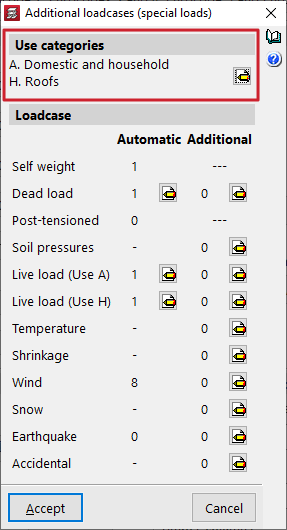
Loadcase
The "Loadcase" section defines the number and type of load for the structure.
Automatic loadcases
The "Automatic" column shows the loadcases that the program automatically considers.
These include the "Self-weight" loadcase, the "Dead loads" loadcase and a "Live load" loadcase for each of the declared service categories.
If the "Wind action" and "Seismic action" options have been previously activated in the "General data" window, automatic loadcases will also be added in the "Wind" and "Earthquake" sections, generated according to the selected standards.
Editing automatic loadcases allows the insertion of different load arrangements, as explained below.
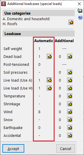
Additional loadcases
In the "Additional" column, additional loadcases can be added if required.
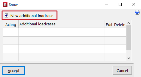
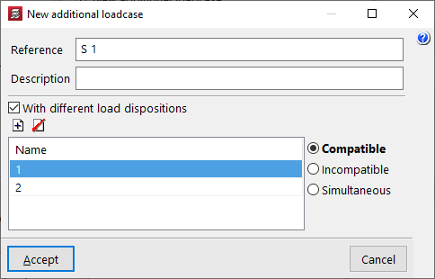
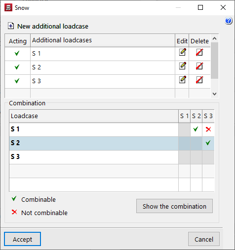
To do this, after clicking the edit button within the desired category, such as "Snow" or "Accidental", click "New additional loadcase" and enter a "Reference" and a "Description".
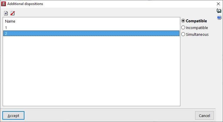
Optionally, the program allows the "With different load arrangements" checkbox to be enabled for each of the added loadcases. This option is also available for the automatic loadcases by clicking the edit button in the corresponding column. The concept of a load arrangement allows different loading states to be defined and grouped within the same load case. Load arrangements may be "Compatible", "Incompatible" or "Simultaneous" with each other.
Combination of loadcases
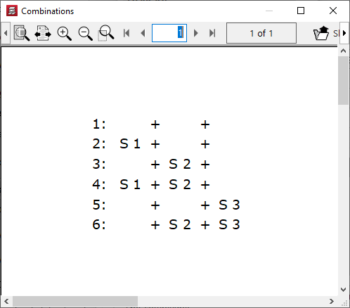
If several additional loadcases are added, the program displays a "Combination" for the different loadcases, where their condition as "Combinable" or "Not combinable" can be specified. The "Show the combination" button allows the "Combinations" obtained after editing the table to be listed.
| Note: |
|---|
| Due to the large number of automatic combinations that can be generated, we recommend not indiscriminately increasing the number of load provisions or combinable loadcases. |
Consider second order effects
In the case of additional horizontal loads such as accidental loads, wind or seismic loads, the program allows users to "Consider second order effects" by ticking the corresponding box and entering a "Value to multiply displacements" which must be estimated by the user.
| Note: |
|---|
| The displacement amplification value for concrete elements can be estimated at 1/0.7 = 1.43, corresponding to a 30% reduction in stiffness, according to Brazilian standard NBR 6118. As a higher value, 1/0.5 = 2 can be estimated, corresponding to a 50% reduction in stiffness, according to the CEB-FIP 1990 Model Code. |
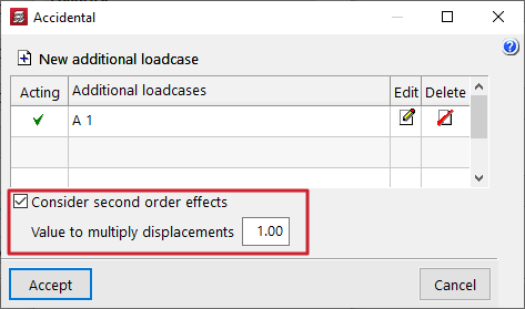
Table of contents
Complete your tour of CYPECAD by exploring the other available sections:
- Introduction
- Introduction and creating new jobs
- General data configuration
- Defining floors and groups of floors and inserting columns, shear walls and starts ("Column input" tab)
- Inserting beams, walls, floor slabs, foundation elements and special elements, and structural analysis (the "Beam Input" tab):
- Checking analysis results and editing elements (the "Results" tab):
- Options on the "Contour plots" tab
- Printing documents and exporting data
- More information:
- General features of CYPECAD