CYPECAD has been created to carry out the design, analysis and sizing of reinforced concrete and steel structures for building and civil works which are subject to horizontal and vertical actions and fire exposure.
This page provides information about the “General data” definitions of a structure that is entered in CYPECAD, as well as the analysis options and general options.
More information about this program can be found on the CYPECAD webpage.
Accessing the “General data” window, analysis options and general options
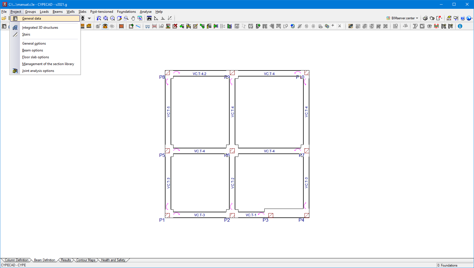
The “General data” window can be accessed from the “Project” menu that can be found in either the “Column definition”, “Beam definition” or “Results” tab.
There are also other analysis options and general options available in the “Project” menu (when it is accessed from the “Beam definition” or “Results” tab).
General data
When entering a structure in CYPECAD, the first step is to define the general data that will condition its analysis and design. Nevertheless, this data can be modified at any time.
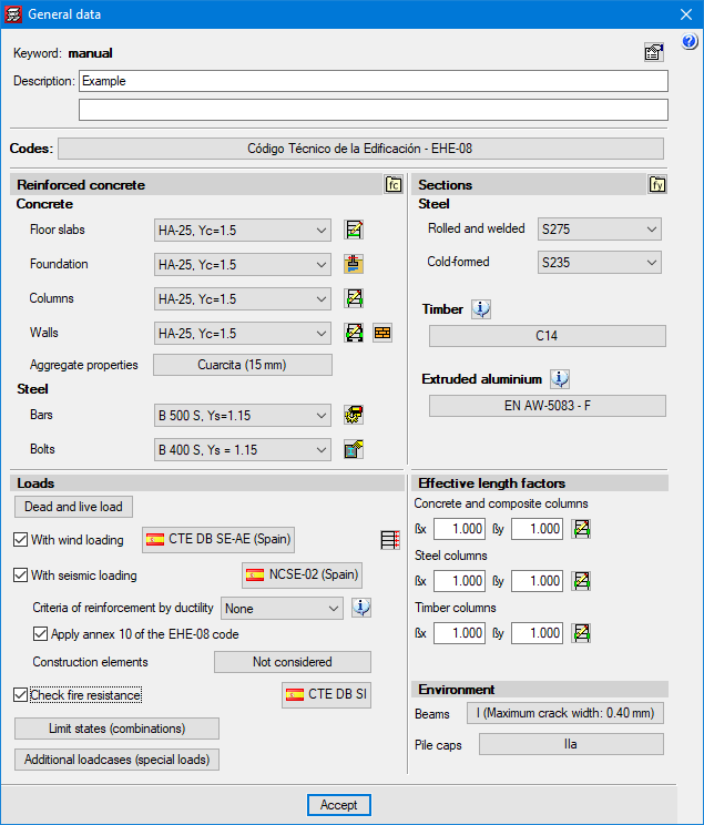
The “General data” window contains several sections:
- Codes
Code selection for each type of material involved in the structural analysis.
Depending on the country from which the licensee has acquired the license, each program will only activate the implemented codes corresponding to that country. More information about this aspect and about the possibility of acquiring additional codes is available under "Programs and design codes included in the user license". - Structural element materials
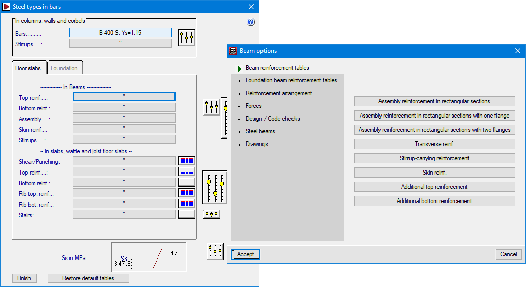
For each type of element and material, its mechanical and strength characteristics are defined. From here, the analysis options and the reinforcement tables that affect reinforced concrete elements can also be accessed. We highlight the design options and reinforcement tables for steel bars that are classified depending on the element and the position they occupy in the element (columns, screens, walls, slabs, beams, foundations, stirrups, top reinforcement, bottom reinforcement, punching and shear, etc.):
- Concrete for floor slabs
- Concrete for foundation
- Concrete for columns
- Concrete for walls
- Steel for bars
- Steel for bolts
- Steel for metal sections
- Timber
- Steel
- Selecting loads
The program automatically generates the self-weight of all the elements entered along with any combination of user-defined loadcases according to the premises they have defined (compatible, incompatible or simultaneous). Project-specific situations can be defined.
- Dead and live loads per floor
- Wind loading
- Selecting features following the description in the selected code
- Considering second order effects (P-delta)
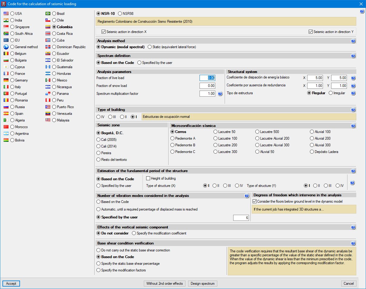
- Seismic loading (modal spectral analysis)
- Selecting features following the description in the selected code
- Considering second order effects (P-delta)
- Criteria of reinforcement by ductility
- Possibility of considering non-structural construction elements
- Fire resistance check
- Ultimate Limit States and load combinations for ground bearing pressures and displacements
- Additional loadcases
- Effective length factors
- Concrete columns
- Steel columns
- Environment
- Beams
- Pile caps
Analysis options and general options
In addition to the analysis options for the reinforced concrete elements that are defined in the “General data” window in the “Project” menu (when it is accessed from the “Beam definition” or “Results” tabs), the following options are also available:
- General options
General drawing options, negative moment redistribution coefficients, torsional stiffness reduction coefficients, inertia reduction factors. - Beam options
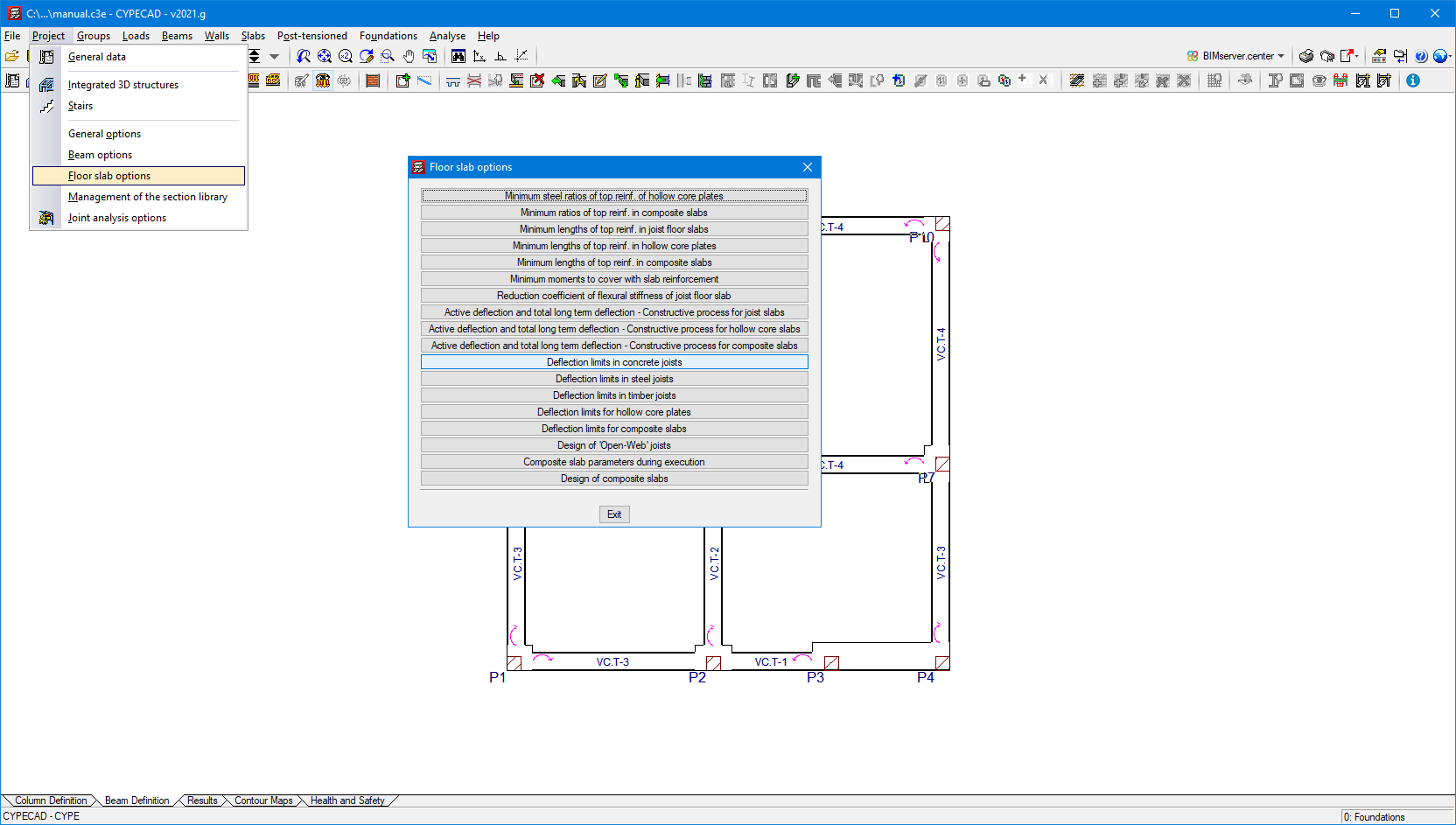
Error colours, shear envelopes, beam options (steel and timber), deflection limits in beams (for concrete, rolled steel, cold-formed steel and timber), effective length factor for sloped beams and for bracing, etc. - Floor slab options
Minimum ratios, minimum reinforcement lengths, reduction coefficient of flexural stiffness, calculating the active deflection and total long term deflection, deflection limits, etc. - Management of the section library
Import and export of section series - Joint analysis options
Bolts and stiffeners