
Project analysis
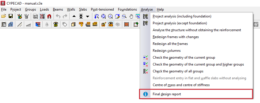
To analyse the project in CYPECAD, open the "Beam input" tab and expand the "Analyse" menu at the top of the interface.
The options that allow the project to be analysed from this menu are described below.
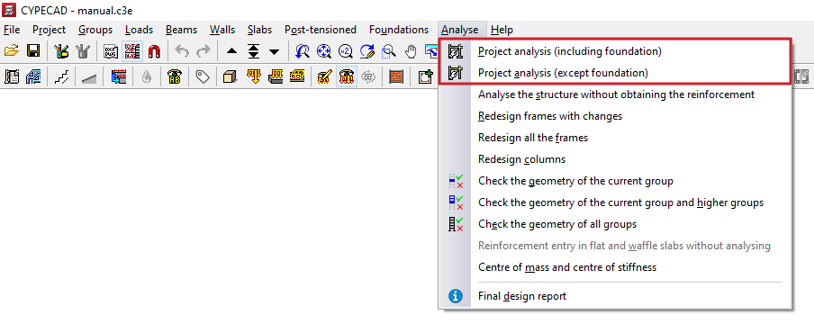
Project analysis (including foundation)
The first option, "Project analysis (including foundations)", is the most comprehensive, as it allows the combined analysis of the structure and the foundation of any type.
Project analysis (except foundation)
The "Project analysis (except foundation)" option allows only the analysis of the structure and slab foundations or foundation beams, without designing foundations by footings or pile caps.
This is possible because foundation systems formed by footings and/or pile caps, and elements such as tie beams and centring beams, are designed in a later and independent phase from the rest of the structure.
Design options
When using either of the two options mentioned above, where applicable, the "Design options" window appears, allowing the analysis and design configuration of the different elements to be adjusted.
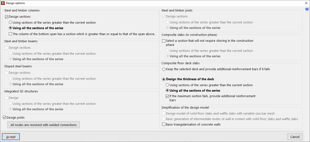
This window offers the following options.
Design sections
The "Design sections" or "Design" checkbox is available for the sections corresponding to the following elements:
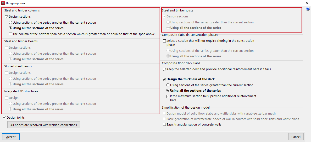
- Steel and timber columns
- Steel and timber beams
- Inclined steel beams
- Integrated 3D structures
- Steel and timber joists
These options allow the automatic modification of the sections assigned to these elements "Using sections of the series greater than the current section" or "Using all sections of the series", including those smaller than the one selected by the user.
In addition, optionally, when designing steel and timber columns, the "The column of the bottom span has a section which is greater than or equal to that of the span above" checkbox can be activated if this condition is required.
The program will not modify the sections of concrete elements during analysis. It will be limited to obtaining their forces, carrying out the checks and designing their reinforcement.
| Note: |
|---|
| Automatic section design must be used with care, as it involves modifying the geometry of the model and may lead to situations not controlled by the user. |
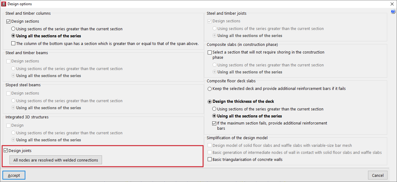
Design joints
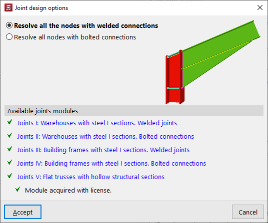
It is possible to activate the "Design joints" checkbox and, in the pop-up "Joint design options" window, decide whether to "Resolve all the nodes with welded connections" or "All nodes are resolved with welded connections" in the same analysis process, provided they are available in the program’s joint modules.
The "Available joint modules" section provides information on the modules purchased in the licence in use. Further information on the capabilities of each connection module can be consulted using the available links.
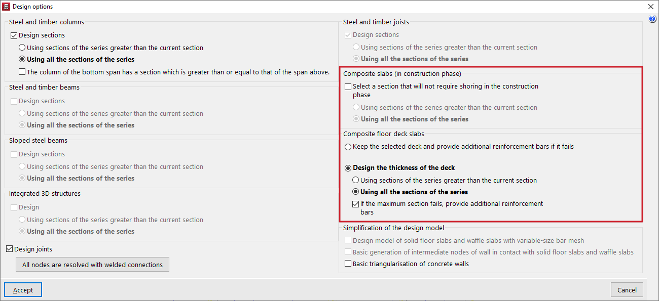
Design composite slab sections
In projects with composite slabs, in the "Composite slabs (construction stage)" section, it is possible to "Select a section that allows props not to be used during the construction stage", when the decking alone supports the applied load:
- If the option is not activated, the program will not modify the section specified by the user and will calculate the spacing between props so that it complies.
- If it is activated, the program will modify the decking section, if possible, to try to eliminate the need for props.
In projects with "Composite slabs with profiled steel decking", it is possible to "Keep the decking and add positive reinforcement bars if it does not comply", or "Design the decking thickness". The program can "If the maximum section does not comply, add positive reinforcement bars" by activating the latter option. If it is deactivated, a non-compliance will be shown in this case.
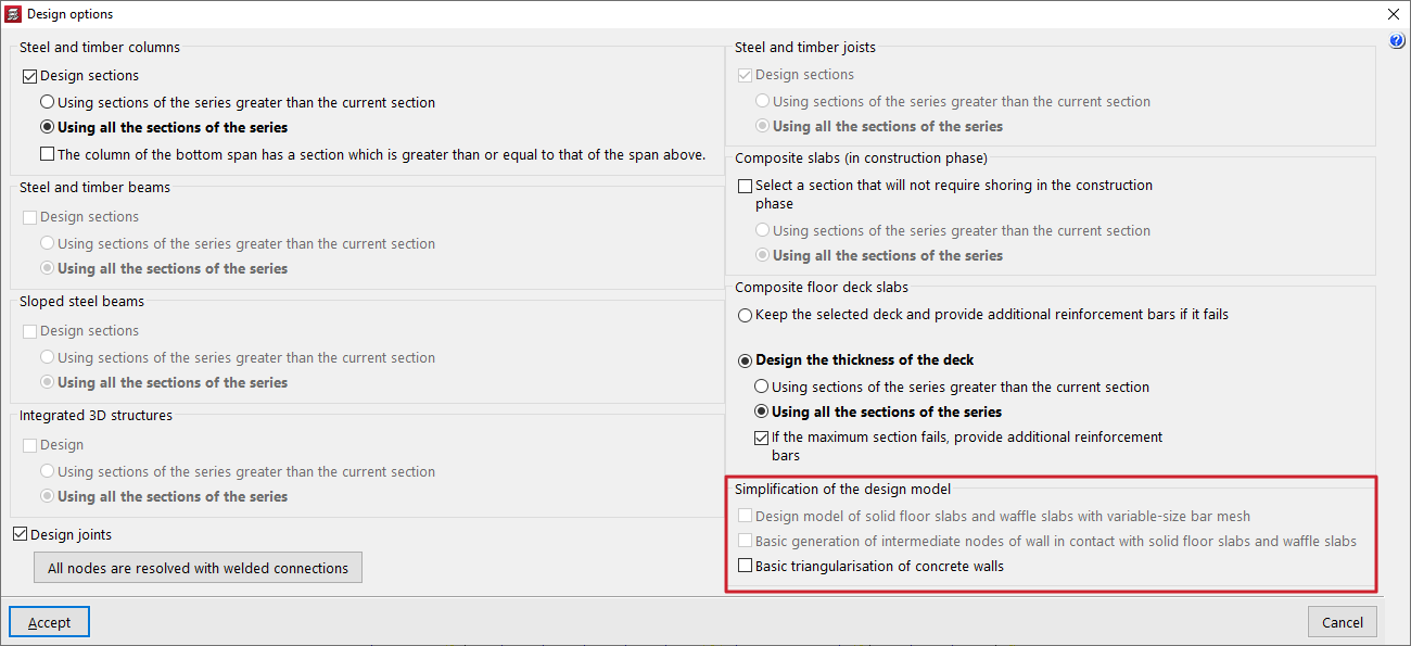
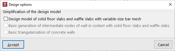
Analysis model simplification options
The program offers the following additional options to simplify the analysis model, thereby reducing the time required to analyse the project:
- Design model of solid slab floors and waffle slabs with variable-side bar mesh
The number of grid elements in the generated analysis model for solid and waffle slab floors is reduced.
- Basic generation of intermediate nodes of walls in contact with solid floor slabs and waffle slabs
If this option is used, the analysis model is simplified in the contact areas between walls and slab floors.
- Basic triangulation of concrete walls
The number of finite elements generated in the analysis model for concrete walls is reduced.
| Note: |
|---|
| The use of these options is recommended in the early stages of analysis in projects that require long analysis times. |
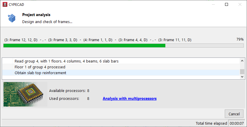
Analysis process
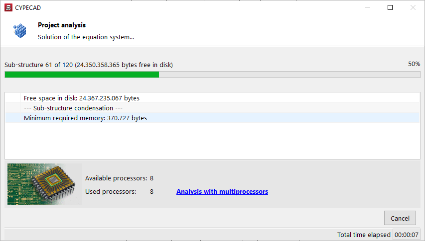
After accepting the "Design options" window, the program launches the analysis process window, which informs the user of the different phases of the process, which run automatically, such as the following:
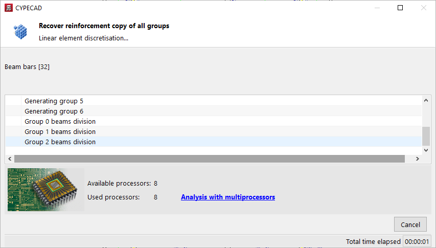
- Discretisation of linear elements
- Optimisation and solution of the system of equations
- Solution of the system of equations
- Obtaining forces and reinforcement in linear and bidirectional elements
- Design and checking of frames
- Reinforcement of vertical elements
- Discretisation, checking and design of foundation elements
Multiprocessor calculation
At the bottom, the number of "Available processors" and "Processors used" is also shown, as well as the "Total elapsed time" since the start of the analysis. In some analysis phases, the program can use a greater number of processors if multiprocessor calculation is available.
Final design report
At the end of the analysis process, the program displays a window with a list of "Project analysis errors", which also includes general information such as the "Analysis time" and other warnings.
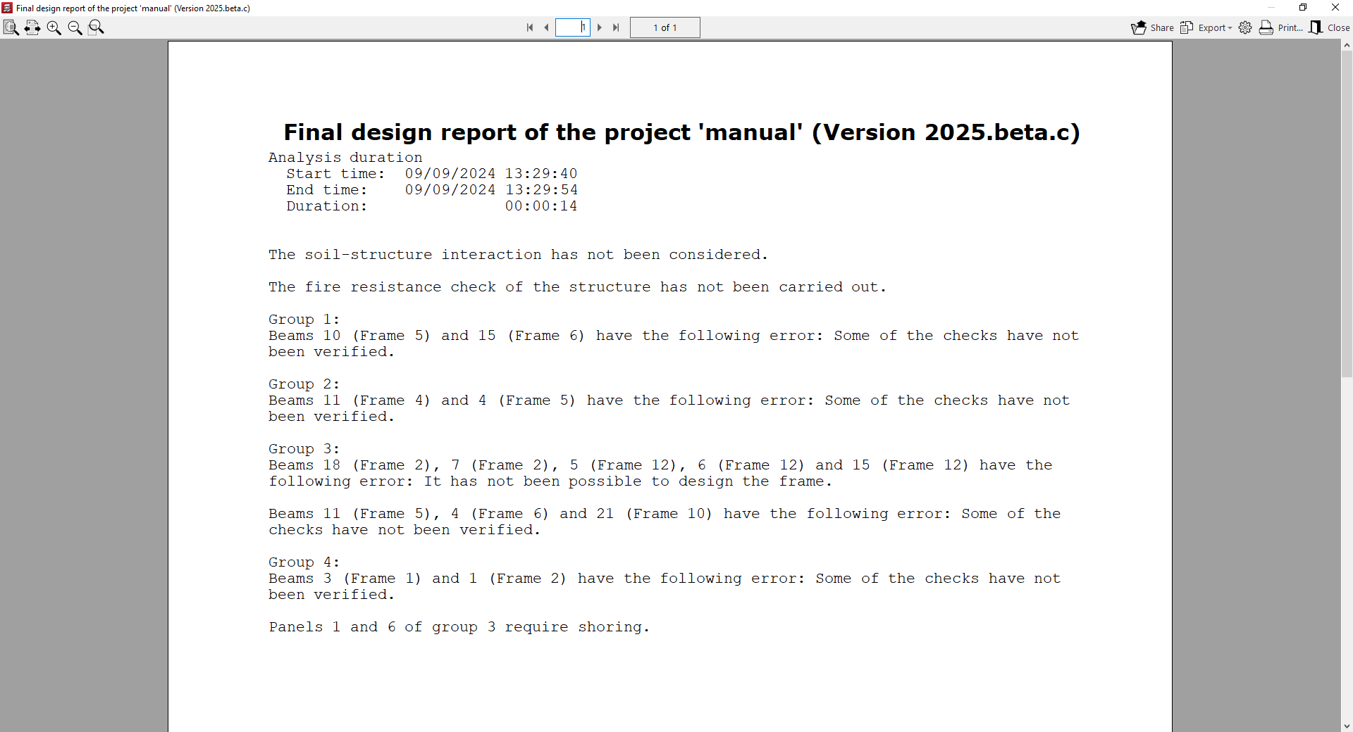
This list can be accessed at any time from the "Analyse" menu by choosing the "Final design report" option.
After analysing, the "Results" and "Contour plots" tabs can be accessed to continue working.
If any geometric modification is made to the inserted elements, such as changing the section of a column or the depth of a slab, the program must account for the modification of the stiffness matrix and, therefore, the project must be analysed again.
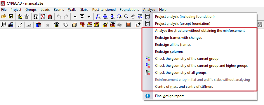
Additional tools in the "Analyse" menu
The following options in the "Analyse" menu described below allow you to make partial adjustments and checks without having to perform a complete calculation of the project, among other features.
Analyse the structure without obtaining the reinforcement
The "Analyse the structure without obtaining the reinforcement" option allows you to calculate only the stresses and displacements of the structure without dimensioning its components, which is done in the final phase of the calculation of the previous options and can increase the duration of the analysis.
When you click on this option, the "Design options" window appears, showing only the "Simplification of the design model" options.
| Note: |
|---|
| Further information on these options can be found at the following link. |
After accepting, the program launches the design process.
Options for redesigning frames and columns
The following options are available if the work has been analysed:
- Redesign frames with changes
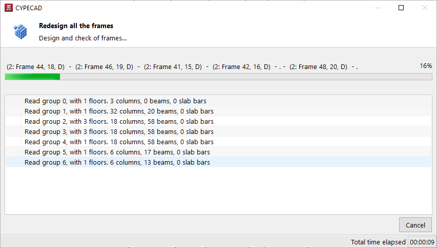
Redesigns the reinforcement of beams whose section has been modified. - Redesign all frames
Redesign the reinforcement for all beams. - Reinforce columns
Redesign the reinforcement for all columns.
These options allow you to reobtain the reinforcement of these elements with the forces from the last analysis and are especially useful if options or reinforcement tables have been modified, or even, in the case of beams, their sections.
However, if the sections have undergone significant modifications, you should redesign to obtain the stresses again.
After using one of these options, the program launches the process of dimensioning and checking the indicated elements. Upon completion, the "Final design report for the project" is displayed, if applicable.
Options for checking the geometry of groups
The following options perform the discretisation of the linear elements of the specified floor groups:
- Check geometry of current group
- Check geometry of current group and superiors
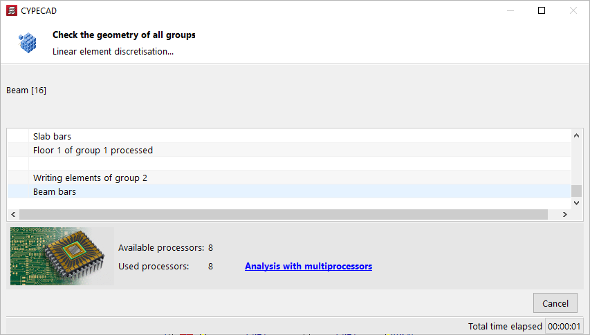
- Check geometry of all groups
Its use allows certain types of errors to be detected before performing the overall calculation of the structure, so that they can be corrected early on. This is particularly useful in large-scale projects.
After using one of these options, the programme launches the process of checking the geometry of the indicated groups. Upon completion, the "Final design report for the project" is displayed, if applicable.
Allow reinforcement to be entered in slabs and trusses without analysis
With the "Allow reinforcement to be entered in slabs and trusses without analysis" option, all the necessary data is generated to be able to enter reinforcement in slabs and reticular structures with the current geometry of the project without having to perform a complete calculation. When doing so, any previous reinforcement is lost, if it exists.
Once the process is complete, you can insert the desired assembly into these elements.
Centre of mass and centre of stiffness
The "Centre of mass and centre of stiffness" option allows you to set the values for "Fraction of live load" and "Fraction of snow load", used to determine the total mass of the building if no seismic action has been selected.
| Note: |
|---|
| The centre of mass and centre of stiffness can be displayed by activating "Centre of mass and centre of stiffness" in "Groups > Visible references". Their position is obtained each time the structure is analysed. |
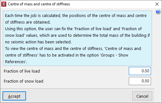
Table of contents
Complete your tour of CYPECAD by exploring the other available sections:
- Introduction
- Introduction and creating new jobs
- General data configuration
- Defining floors and groups of floors and inserting columns, shear walls and starts ("Column input" tab)
- Inserting beams, walls, floor slabs, foundation elements and special elements, and structural analysis (the "Beam Input" tab):
- Checking analysis results and editing elements (the "Results" tab):
- Options on the "Contour plots" tab
- Printing documents and exporting data
- More information:
- General features of CYPECAD