
Consulting beam errors
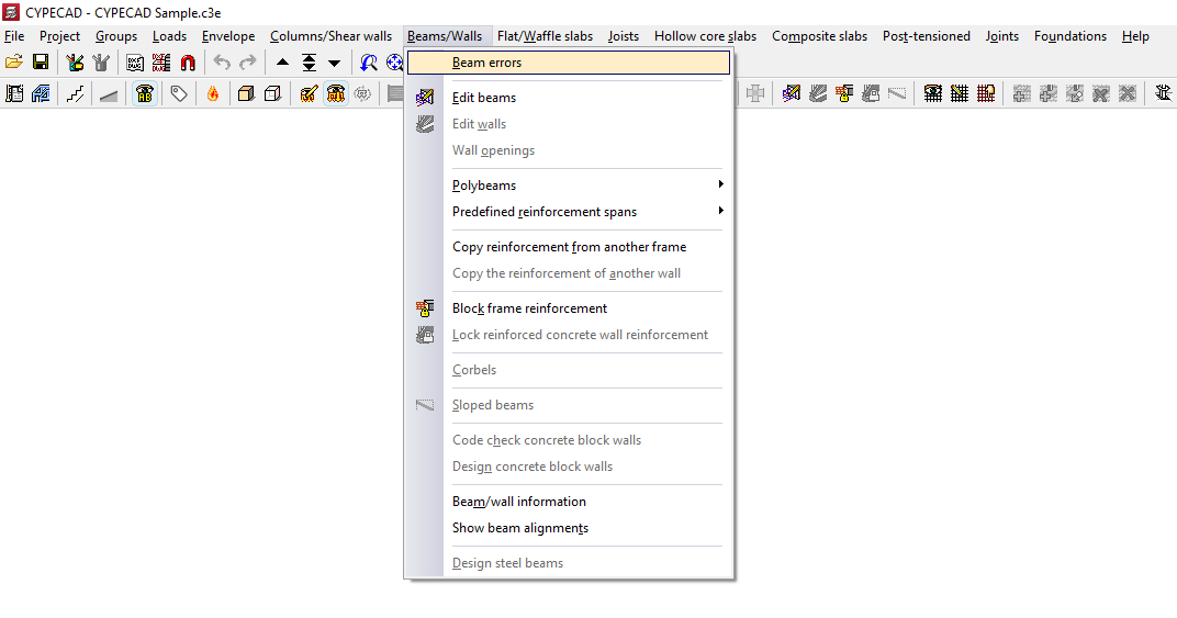
To view beam errors in the program after analysing the structure, open the "Results" tab and select the "Beams/Walls" menu at the top of the interface.
Next, select "Beam errors" and click on any of the beams in the group.
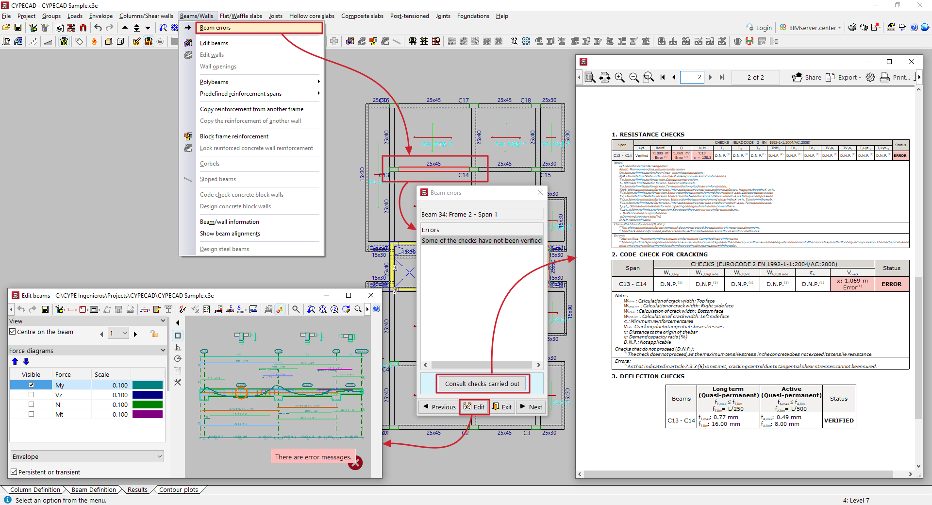
Beams with any verification errors will be highlighted in red.
The program will indicate the reference of the beam, frame and span. Then, in the "Errors" table, it will display a list of warnings generated after the analysis:
- If the selected beam passes all checks, the text "No errors" will be displayed.
- If the text "Some of the checks have not been verified" is displayed, it is possible to "Consult checks carried out" in a pop-up window using the corresponding button.
The "Previous" or "Next" options allow you to move from one beam in the group to another, while the "Edit" button gives you access to the beam editor. To close this window, use the "Exit" option.
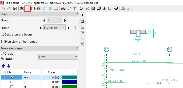
Accessing the beam editor
CYPECAD automatically designs the reinforcement of beams during the analysis process in order to comply with the various checks required by the selected standards. It is then possible to view and edit the reinforcement arranged in the beams and check the modifications made.
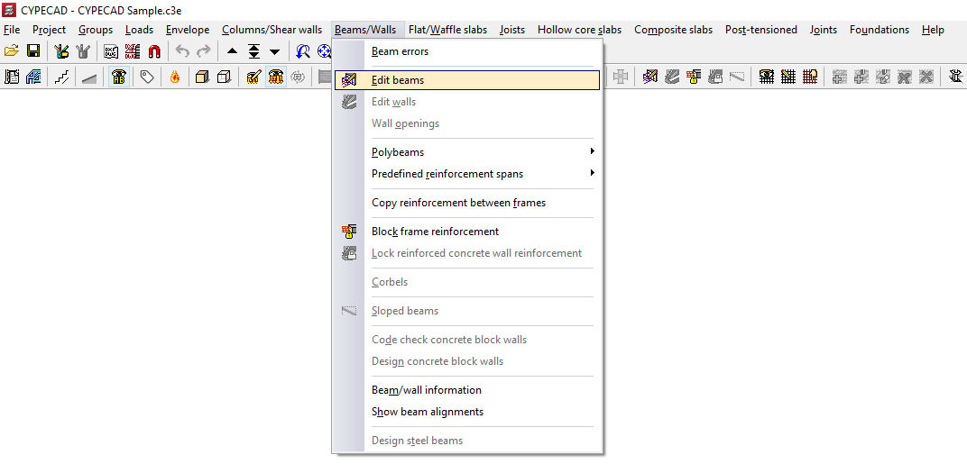
The beam editor can be accessed from the "Results" tab in several ways, after opening the Beams/Walls menu at the top of the interface:
- Using the "Edit beams" option and selecting one of the beams in the group.
- Using the "Beam errors" option, select one of the beams in the group and then click on the "Edit" option.
The beam editor may appear differently depending on the regulations used. The advanced beam editor will appear if you are working with regulations that allow its use.
Beam editor
The beam editor allows users to review the internal forces, design, and checks automatically performed by the program for all beams in the job. Using the editor, you can modify the reinforcement or steel sections used and verify all the changes made, then generate detailed check reports.
Beam editor interface
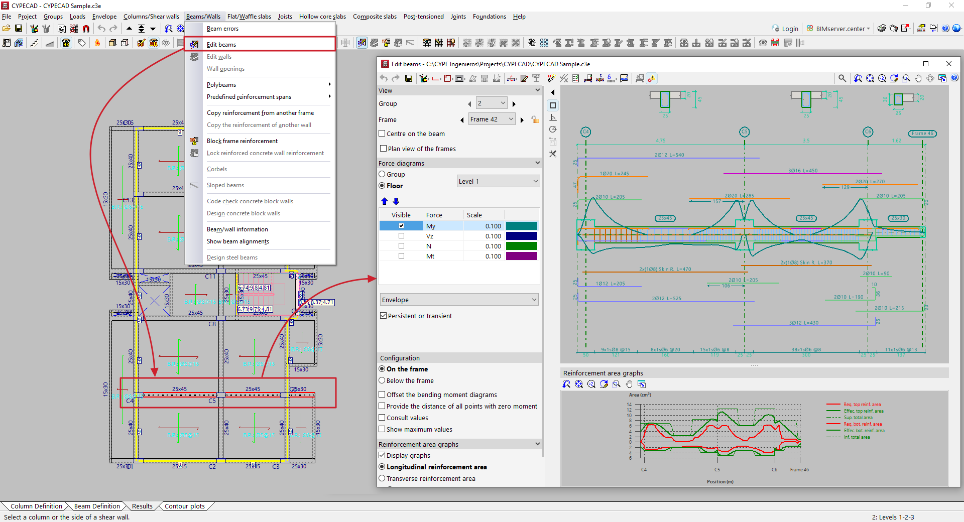
The interface of the beam editor includes the following areas and features:
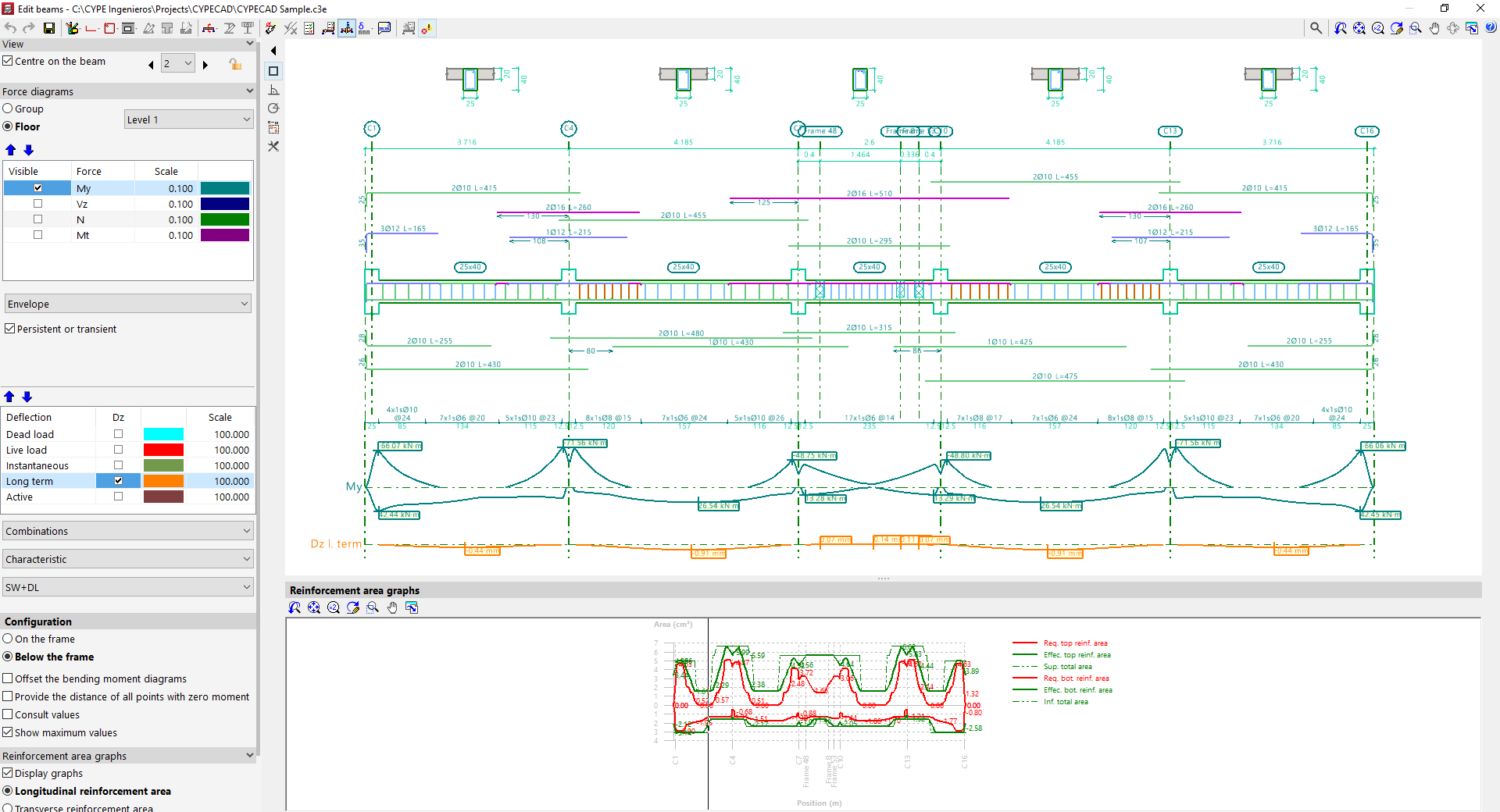
Top toolbar
- At the top of the window, various editing and verification tools are available for the beams in the displayed frame.
Viewers
- The main viewer in the upper right displays a longitudinal section view of the frame being edited. For reinforced concrete beams, it shows the longitudinal and transverse reinforcement generated after calculation. At the top, the generated cross sections are also shown.
- The secondary viewer at the bottom displays the "Reinforcement area graphs". The required area is shown in red, and the effective area of the placed reinforcement in green. The most critical or most used points in terms of reinforcement are those where the effective reinforcement graph is closest to the required reinforcement graph.
Side options panel
- On the left side, in the "Display" section, the program indicates the "Group" and the "Frame" currently shown in the viewer. The "Centre on beam" option allows you to centre the view on the desired beam, while activating "Plan view of frames" adds a schematic plan view. Clicking the left and right arrows allows you to navigate to the next group, frame, or beam. It is also possible to lock the reinforcement of the frame using the corresponding button. This will prevent the program from modifying the frame’s design in subsequent analyses, but it will not prevent manual edits in the editor.
- In the "Force diagrams" section, visibility of various internal forces is enabled, along with their scale and colour, such as the bending moment, shear force, axial force, or torsional moment.
- The lower dropdown menu lets you choose whether to view the "Envelope" of forces or one of the available "Load cases" or "Combinations"
- If the options "ULS and SLS checks at critical point", "ULS and SLS checks at a point", or "Check deflection in spans" are selected at the top, additional options for "Deflection" appear in this side panel, which can be reviewed in the same way as the force diagrams.
- In the "Configuration" subsection, you can choose whether the force diagrams are shown "Above the frame" or "Below the frame". Additional options include "Offset bending moment diagrams", "Mark zero moment points", and "Show values", which allows hovering over the diagram to see the force value at a specific section, as well as "Show maximum values".
- In the "Reinforcement area graphs" section, the "Show graphs" option toggles the display of the secondary viewer. Users can select whether to display the "Longitudinal reinforcement area" or the "Transverse reinforcement area", and whether to show it "By resistance and minimum ratios" or only "By resistance". It's also possible to "Show area values" in the viewer by enabling the last option.
Beam editor tools
The tools at the top of the beam editor allow the following operations to be performed.

- First, it is possible to "Redo", "Undo", or "Save" the changes made using the options described below
- The "Editing resources" button (available in CYPECAD) allows you to insert graphic aids such as lines, text, and dimensions on the drawing.
- Further to the right, there are options to modify the "Longitudinal reinforcement" and "Transverse reinforcement of the beam", as well as to insert "Openings" in the beam.
- For specific cases involving truss beams and prestressed beams, it is possible to modify the "Trusses", "Infilled" beams, and the selection of "Prestressed beams".
- The "Transverse sections" option allows them to be generated automatically, to "Enter a transverse section defined by a single point" or "Enter a transverse section defined by two points", and to delete them. Cross sections are displayed above the frame.
- The "Edit section" option allows the beam's section to be modified.
- "Shear studs for composite beams" can also be modified for this type of beam.
- The "Redesign" option forces the program to automatically re-design the frame using the internal forces from the analysis, applying the reinforcement tables and discarding any manual modifications made.
- The "Checks" option allows you to examine the series of sections used in steel, composite, or timber beams. The program displays a table indicating the "Section that passes all the checks" and the "Section that fails a check", along with the reason stated in the "Errors" column. It also displays each section’s "Weight", "Usage due to resistance", and "Demand capacity ratio - deflection". Selecting one and accepting will result in a section change.
- By selecting "U.L.S. and S.L.S. checks at the worst case point" and then clicking on a beam, the program shows the results of each check at the most unfavourable point. All performed checks are shown individually, each marked with its "Status". At the bottom, the verified code clause or article is displayed, along with a breakdown of the analysis process followed in each case. To obtain a detailed report of all checks, use the "View full report" option. This information can be "Exported" in different formats, "Shared", or "Printed".
- To obtain "U.L.S. and S.L.S. checks at a point", click on the corresponding option and then select the desired beam. The program will show a series of points along the beam, representing the locations of the verification sections. Clicking on any of them displays the specific check report for that point. As with the previous option, you can "View full report", as well as "Export", "Share", or "Print" the information.
- The "Consult deflections in spans" option allows you to move the pointer over the spans of the selected beam to display the calculated deflection information.
- Additionally, the "Deflection groups" option (available in CYPECAD) allows automatic generation or manual editing, as well as merging or splitting of existing deflection groups. It is also possible to modify the "Support conditions" of the beam by selecting one of the available predefined cases, and to define the "Deflection type" as "Secant deflection", "Tangent to start node", or "Tangent to end node".
- Similarly, the "Consult the required and effective areas" option allows you to move the cursor along a beam and view the steel areas at the point where the pointer is located.
- The "Update error information" option forces the program to recheck the frame after modifications have been made to its section or reinforcement. After using this option, you can return to the check reports and review the outcome of the changes.
- Lastly, the "Show/Hide issues" option enables or disables the display of issues. These are shown in the main viewer over the beam with problems. Hovering the pointer over them displays an informational message explaining the issue.
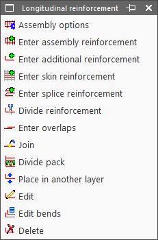
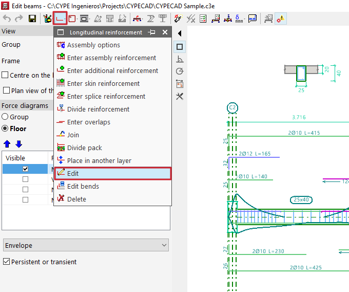
Editing longitudinal reinforcement of beams
The editing tools for longitudinal reinforcement are located at the top of the beam editor window and include the following:
- Assembly options
- Enter assembly reinforcement
- Enter additional reinforcement
- Enter skin reinforcement
- Enter splice reinforcement
- Divide reinforcement
- Enter overlaps
- Join
- Divide pack
- Move to another layer
- Edit
- Edit bends
- Delete
These options are explained below:
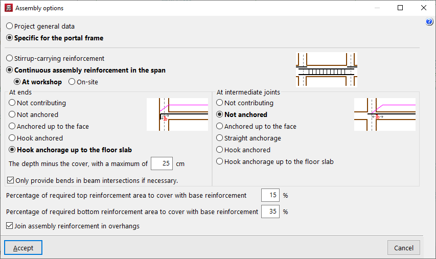
Assembly options
This option allows you to choose whether to use the general configuration for assembling reinforcement defined in "General project data" (Project > General data > By position > Beam options > Design / Check > Mounting reinforcement) or to use the options "Specific to the frame".
Enter assembly reinforcement
The "Enter assembly reinforcement" option allows you to select a beam that does not already have defined assembly reinforcement, or to define the initial and final nodes of the assembly reinforcement cage, as long as they are aligned.
Next, you specify the top and bottom reinforcement, the layout of the transverse reinforcement, and the bend definitions at the bar ends.
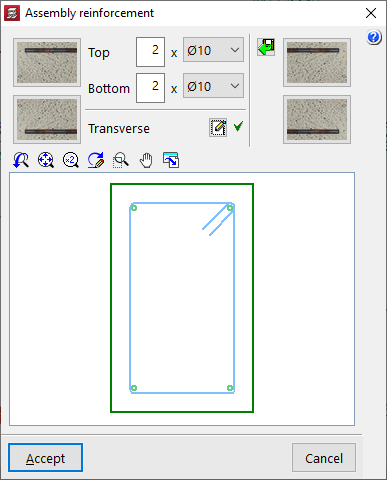
The program also allows you to "Import an admissible arrangement from the assembly reinforcement table" by clicking the button on the right. After selecting a row in the table, accept the panel.

Enter additional reinforcement
To "Enter additional reinforcement", you define the number of bars and their diameter. Optionally, you can "Select the layer upon entering the reinforcement".

Then, position the pointer on the top or bottom of the frame, depending on where the reinforcement is to be placed, and click two points to define the spacing between the ends of the reinforcement bundle.

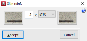
Enter skin reinforcement
To "Enter skin reinforcement", simply click on the beam and specify the number and diameter of the bars.
This reinforcement will be placed on both sides of the beam.

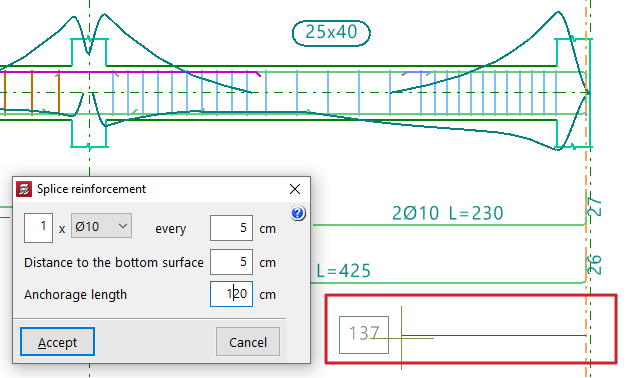
Enter splice reinforcement
To "Enter splice reinforcement", click one end of the beam, move the pointer inward across the span, and click again to indicate the "Distance" between bars.
Next, define the number and diameter of bars, spacing, "Distance to the bottom surface", and "Anchorage length".

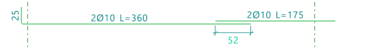
Divide reinforcement
The "Divide reinforcement" option allows you to select a point on a reinforcement bar and introduce a lap, splitting the bar into two bundles.
In the "Lap layout" section of the dialogue box, you can select the lap type:
- Lap centred on the selected cut point
- Lap to the left of the selected cut point
- Lap to the right of the selected cut point
At the bottom, you specify the "Lap length".

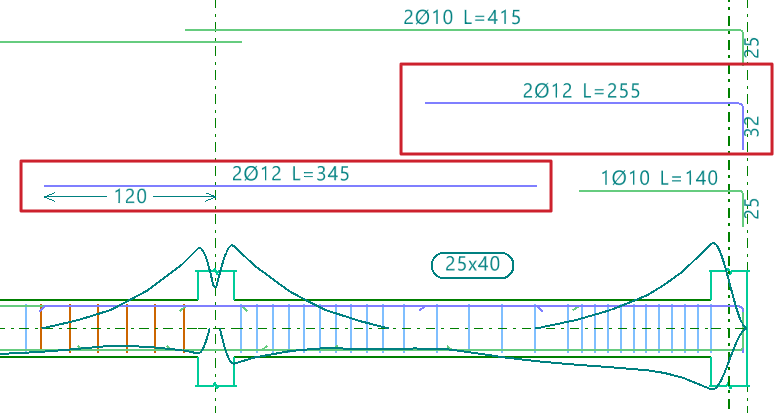
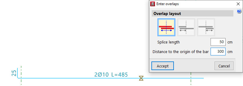
Enter overlaps
The "Enter overlaps" option allows you to select a point on a reinforcement bar and enter a lap without splitting the reinforcement group.
As with the previous option, in the "Lap layout" section, you can choose:
- Lap centred on the selected cut point
- Lap to the left of the selected cut point
- Lap to the right of the selected cut point
You also define the "Lap length", and additionally, the "Distance to the origin of the bar".
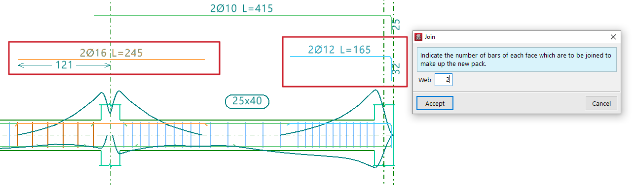
Join
The "Join" option allows you to combine multiple reinforcement bundles of the same type and face into a single one.You must specify the number of bars that will form the new bundle.
The program will take the diameter from the first selected bundle.
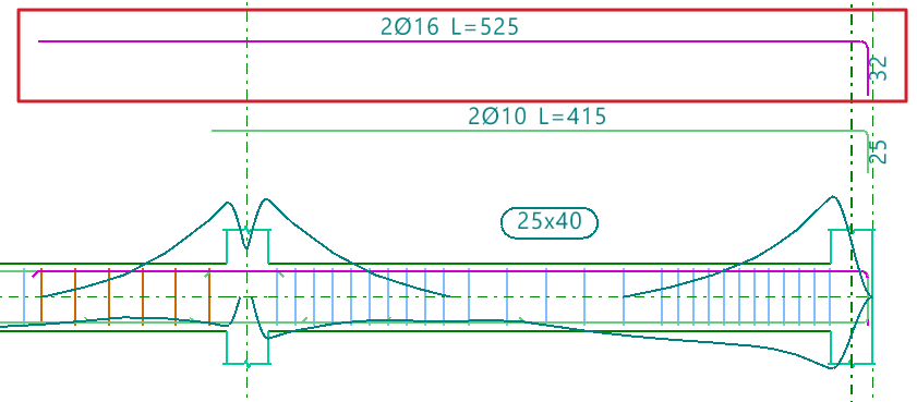
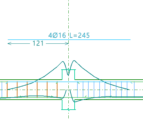
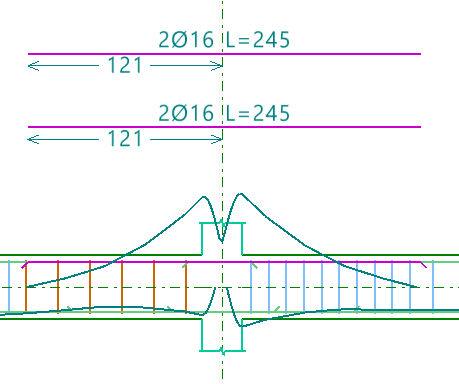
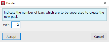
Divide pack
The "Divide pack" option allows a reinforcement bundle containing at least two bars to be divided into multiple bundles, enabling independent editing.
You must specify how many bars will be separated to form the new pack.
Place in another layer
The "Place in another layer" option allows you to select one or more reinforcement bundles and, after right-clicking, specify the layer where they will be placed.
These changes are evident in the beam's cross section. The program also considers the reduced lever arm in design checks when these changes are made.
Edit
The "Edit" option allows direct modification of reinforcement bars displayed in the main viewer after calculation.
Editing assembly reinforcement
Clicking on the assembly reinforcement lets you adjust the number of bars and select their diameter for both the "Top" and "Bottom" layers.
You can also modify the "Transverse" reinforcement by clicking the corresponding button. In the resulting window, you can edit the Type of stirrup or "Type of branch", add stirrups or branches of different types by clicking on the longitudinal bars in the graphic, or "Delete reinforcement".

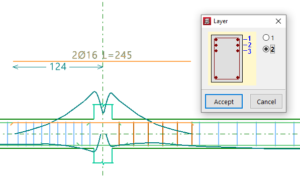
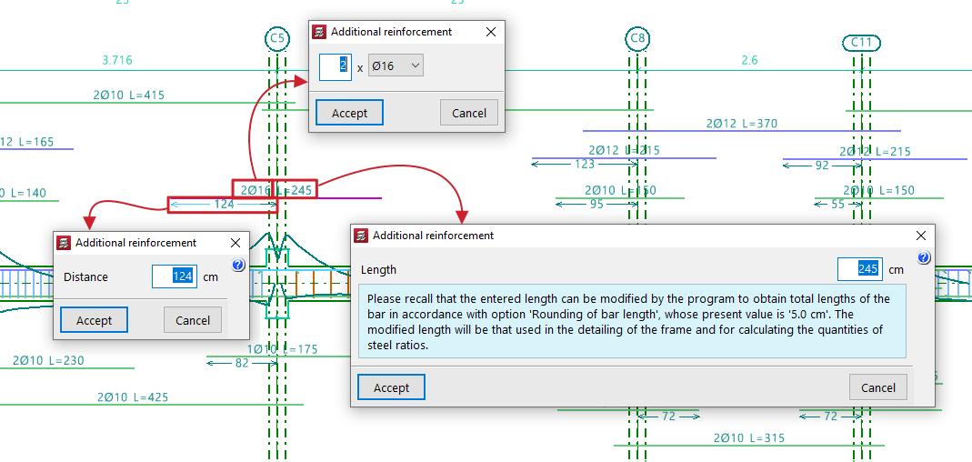
Editing additional reinforcement
To edit additional reinforcement, click on the descriptive labels of the bars in the main viewer. You can modify the number and diameter of bars, their Length, and the Distance between them, as well as the length and type of "Bend" if an end is selected.
When hovering near a bar’s end, a double arrow appears. Clicking it allows you to lengthen or shorten the bar. The program displays the bar’s total length on screen during this adjustment.
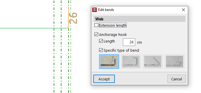
Edit bends
The "Edit bends" option allows you to modify bar hooks. All bends in the frame can be selected by drawing a selection box over it.
You can set the "Length" and select a "Specific type of bend" from the following:
- 90º bend
- 90º bend with horizontal extension
- 135º bend
- 180º bend
Delete
To delete reinforcement, use the "Delete" option and click on the reinforcement to remove it.
Verification, checks and saving changes

After making any reinforcement modifications, click the "Update error information" option in the top toolbar to verify the frame after the changes.
Once this is done, you can use the "U.L.S. and S.L.S. checks at the worst case point" and "U.L.S. and S.L.S. checks at a point" options to view the check reports and examine the results of your changes.
Finally, you can "Save" your work on the frame using the corresponding option.
If you want to exit the editor without keeping the changes, you can close the editing window and confirm in the dialogue box that appears.
Editing transverse reinforcement in beams
The following describes the options available in the beam editor for viewing or editing the transverse reinforcement in beams.
Editing the layout of the transverse reinforcement
To view the layout of the beam’s transverse reinforcement as determined by the analysis, open the editing panel for the entered assembly reinforcement. To do this, open the "Longitudinal reinforcement" menu at the top, select the "Edit" option, and click on the beam’s assembly reinforcement in the main viewport on the right.
| Note: |
|---|
| The "Enter assembly reinforcement" option in the "Longitudinal reinforcement" menu allows you to define the layout of the transverse reinforcement in the same way. |
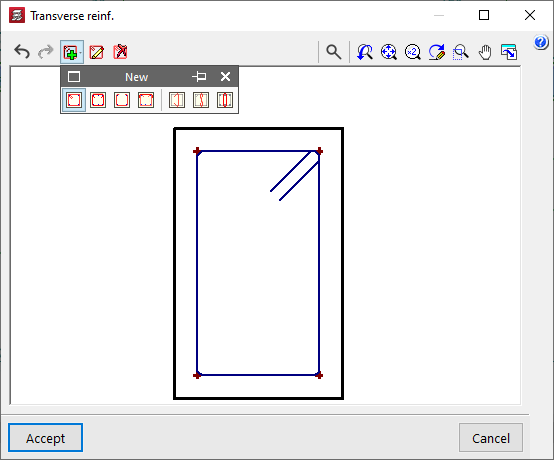
In the window that appears, select the button in the "Transverse" section. From here, using the "Edit reinforcement" option and selecting the stirrups or bars, you can view or modify their type.
The following options are available among the stirrups:
- Closed stirrup
- Closed stirrup with top crosstie overlapping
- Open stirrup
- Open stirrup with top closing crosstie
In the case of branches, the available options include:
- Straight crosstie
- 'S' crosstie
- Closed crosstie
To "Delete frames", click on the option and then on the frames in the viewer.
The "New" option allows you to add new stirrups and branches of the types described. After selecting the stirrup type, click on the starting longitudinal bars and then on the ending longitudinal bars that enclose the transverse reinforcement. In the case of branches, they are added by selecting the longitudinal bars that connect those branches. Once the layout of the transverse reinforcement has been defined, confirm the window.
In the assembly reinforcement editing window, the program also allows you to "Import an admissible arrangement from the assembly reinforcement table" by clicking on the corresponding button on the right-hand side.
Selecting one of the rows in the table defines the longitudinal reinforcement and, in addition, a transverse reinforcement layout with a specific number of stirrups and bars.
Editing the diameter, spacing, number of bars and sections of transverse reinforcement
The remaining editing tools relating to the transverse reinforcement of beams can be found in the "Transverse reinforcement" menu at the top of the "Edit beams" window.
This menu offers the following options:
- Edit template
- Edit reinforcement
- Divide reinforcement spans
- Match reinforcement spans
- Delete reinforcement spans
Each of these options is described below.
Edit template
If an assembly configuration has not yet been defined for the beam, the "Edit template" option allows you to specify the "Number of bars" that will be tied by the stirrup for the span.
Edit reinforcement
The most common approach is to use the "Edit reinforcement" option, which then allows you to select the transverse reinforcement section located at the bottom of the portal section. The program allows you to tick or untick the box "Provide reinforcement in this span" and specify a "Transverse reinforcement arrangement", which can be "The same as for the assembly reinforcement" or "Specific to this interval". In the latter case, it must be defined as described above by clicking the button on the right-hand side.
In either case, once the arrangement of the transverse reinforcement has been defined, the "Diameter of the stirrups", the "Spacing between reinforcement bars" and the "Number of grouped stirrups" are specified, and, if applicable, the "Diameter of the branches" and the "Number of grouped branches".
Divide reinforcement spans
To "Divide reinforcement spans", click on the relevant option and then on the point where you wish to split the stirrup. Next, confirm the "Distance".
| Note: |
|---|
| This option allows you to create areas where stirrups are concentrated or to edit the created reinforcement sections individually, changing the diameter or spacing between the reinforcements within them. |
Match reinforcement spans
The "Match reinforcement sections" option allows you to apply the "Layout", the "Diameters", the "Spacing" or the number of "Grouped hoops and branches" of the selected reinforcement section to any other sections selected subsequently.
Delete reinforcement spans
Finally, the "Delete reinforcement spans" option allows you to delete sections of stirrups, whilst ensuring that at least one stirrup section remains on each beam.
Checking, verifying and saving changes
After making any changes to the reinforcement, click on the "Update error information" option in the top toolbar to check the frame following the changes made.
After selecting this option, you can use the "U.L.S. and S.L.S. checks at the worst case point" and "U.L.S. and S.L.S. checks at a point" options to access the check lists and review the results of the changes.
Finally, you can "Save" the results of your work on the portal using the relevant option. If you wish to exit the editor without saving your changes, you can close the editing window and confirm this in the dialogue box that appears.
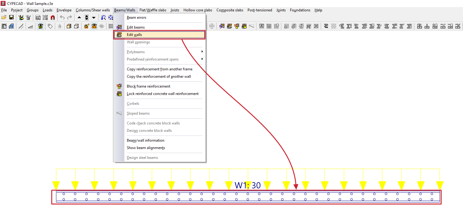
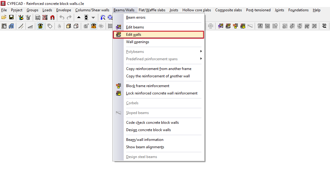
Editing walls
The "Edit walls" option, located in the "Beams/Walls" menu on the "Results" tab, allows you to view and modify the results obtained for the selected wall.
The editing window displays different options depending on the type of wall being edited.
Editing reinforced concrete walls
When editing a reinforced concrete wall, the program opens the "Reinforcement editing" window.
The elevation diagram on the left shows the wall in its full height. The section of wall between floors that is being examined is highlighted in cyan.
There are two ways to change the wall section: by selecting the desired section from the "Selection" drop-down menu, or by clicking on the diagram at the section where you wish to view the reinforcement.
The bottom of the page also shows a plan view of the wall, which includes the structure's general layout, the direction of the wall, and an indication of the positions of its left and right sides.
Checking and editing thicknesses and reinforcements
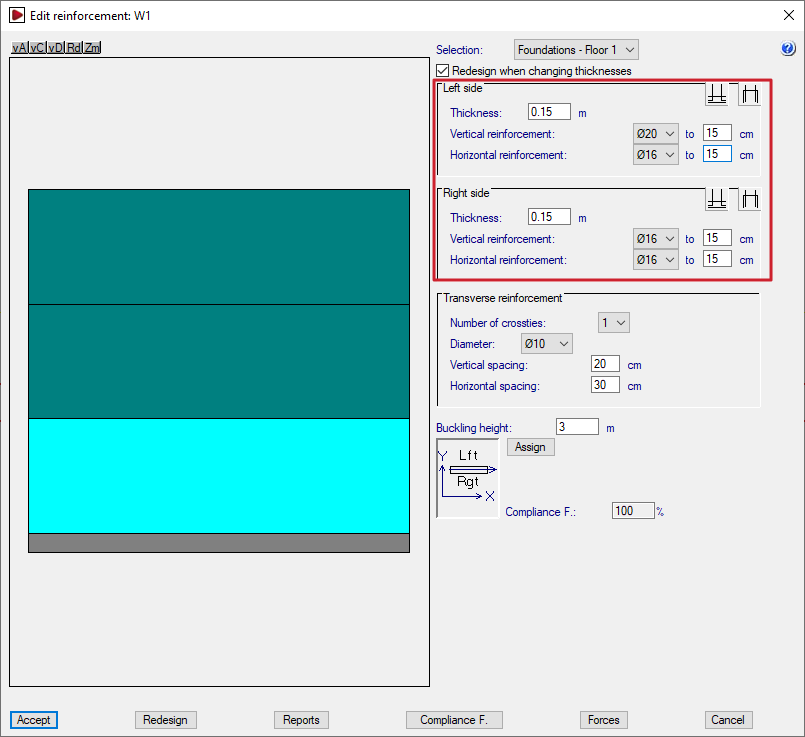
Once the selection has been made, the reinforcements for the section are displayed on the right.
If the "Redesign when changing thicknesses" option is enabled, the program will redesign and check the concrete section using the analysed forces whenever the thicknesses are modified in this window.
In the "Left side" and "Right side" sections, the program allows you to modify the following:
- the "Thickness" of each side of the wall;
- the diameters and spacing of the "Vertical reinforcement" and the "Horizontal reinforcement" on each side of the wall;
- and, using the relevant buttons, the "Overlap on upper floor" and "Start at floor base" on each side of the wall, as appropriate. The "Overlap length" is defined here.
If the "Thickness" label for the wall is displayed in red, this indicates that the concrete section is insufficient.
Similarly, if the labels on some of the reinforcement bars are shown in red, this indicates that those bars are insufficient to absorb the full load. In this case, additional reinforcement is provided at specific points as required.
| Note: |
|---|
| The lap and column start lengths are reanalysed if the vertical reinforcement is modified, with minimum lap or column start lengths always being applied, depending on the diameter and spacing of the vertical reinforcement. Where there is a significant change in the wall cross-section such that the reinforcement must be anchored at the base or on the top floor, the laps are analysed based on the forces at the top of the wall. |
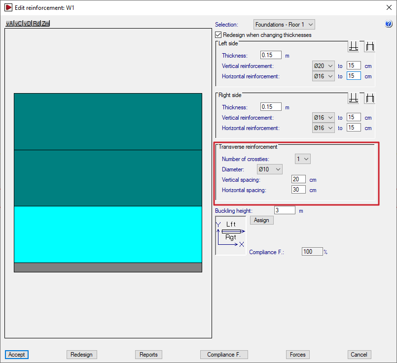
Transverse reinforcement
The "Transverse reinforcement" section allows you to modify the wall's transverse reinforcement. This is defined by the following parameters:
- the "Number of crossties" at each node;
- the "Diameter" of the bars;
- the "Horizontal spacing" and the "Vertical spacing". If this spacing is the same as that of the longitudinal reinforcement, it means that all the bars are tied. If the spacing of the longitudinal reinforcement is less than that of the transverse reinforcement (for example, 15 and 30, respectively), only some of the longitudinal bars between faces are tied (in this example, 1 in every 2 longitudinal bars).
As in the previous section, if the reinforcement or cross-section is insufficient, the text appears in red.
The proposed transverse reinforcement consists of one (or more, depending on the defined "Number of crossties") S-shaped branch connecting the bars between faces at all cross-joints between the wall’s longitudinal bars (horizontal and vertical), thereby linking the reinforcement on both sides of the wall.
Buckling height
The program analyses and displays the value of the "Buckling height" for the selected wall section in the corresponding field. This value affects the slenderness check in the various standards, where applicable. In any case, this value can be modified by the user.
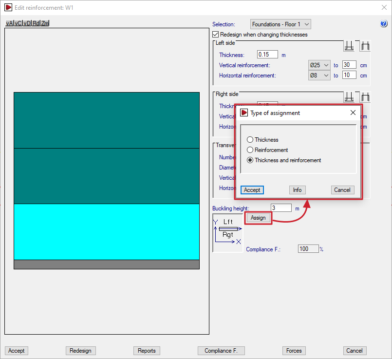
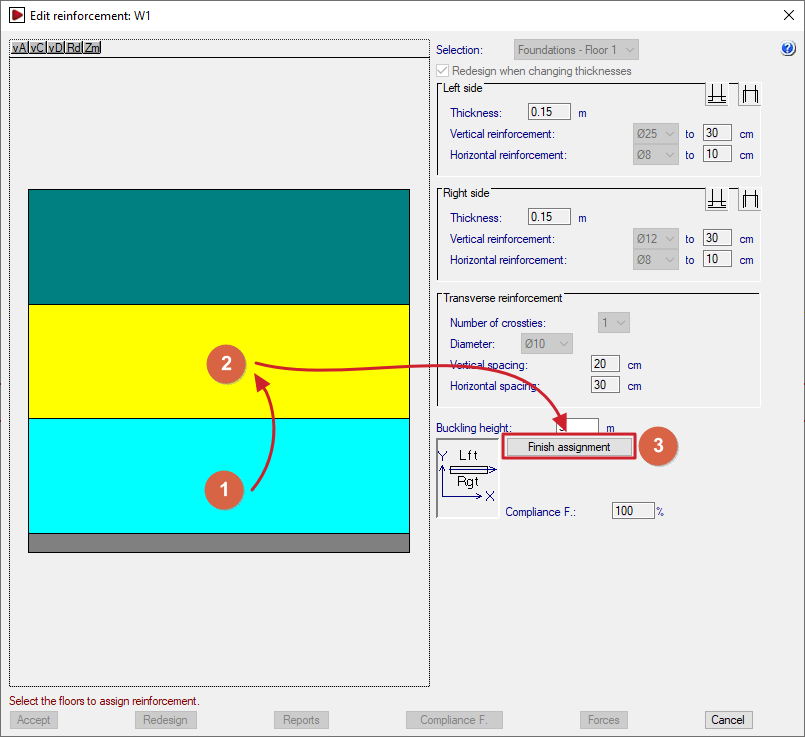
Assigning thicknesses and reinforcements
The "Assign" option allows you to copy the thickness and/or reinforcement of the section being edited to other wall sections, depending on the option selected.
When clicking "Accept" in the dialogue box that appears, the sections with a thickness and/or reinforcement matching the selected settings will be highlighted in light cyan, and the rest in dark cyan.
Next, use the mouse to select the sections to which you wish to apply the properties of the selected section. Each section you select will turn yellow.
To complete the operation, click on "Finish assignment".
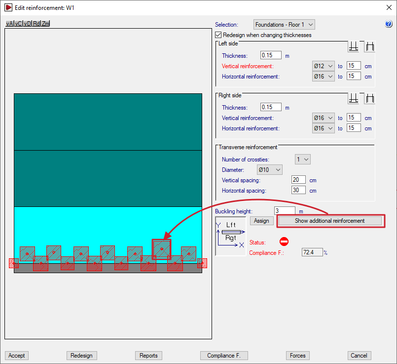
Additional reinforcement
You can view the additional reinforcement by clicking on "Show additional reinforcement" and double-clicking on each red square shown on the wall elevation drawing.
These points correspond to the control nodes of the finite element mesh that discretises the wall, such as the vertices and midpoints of the triangles that make it up.
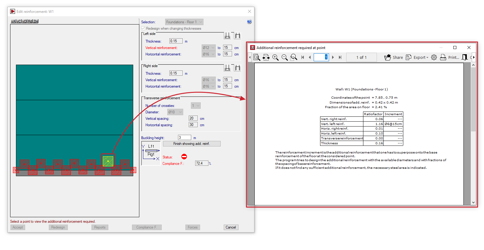
This opens the "Additional reinforcement required at point" window, displaying information such as the following:
- the reference number of the wall and the section in question;
- the "Point coordinates" of the reinforcement in question, the "Reinforcement dimensions", and the "Proportion of the floor area";
- for each type of reinforcement (vertical and horizontal reinforcement on both the right and left sides of the wall, and transverse reinforcement), the "Quantity factor" and, where applicable, the "Reinforcement increment" required to achieve the analysed steel cross-section, specifying the diameter of the bars and their spacing. The reinforcement increment is the reinforcement that must be added to the base reinforcement of the wall section at the point in question.
To finish viewing the additional reinforcement, click on "Finish showing add. reinf.".
| Note: |
|---|
| The program attempts to dimension the reinforcement using the available diameters and fractions of the base reinforcement spacing. If no suitable reinforcement is found, the required area of steel is indicated. |
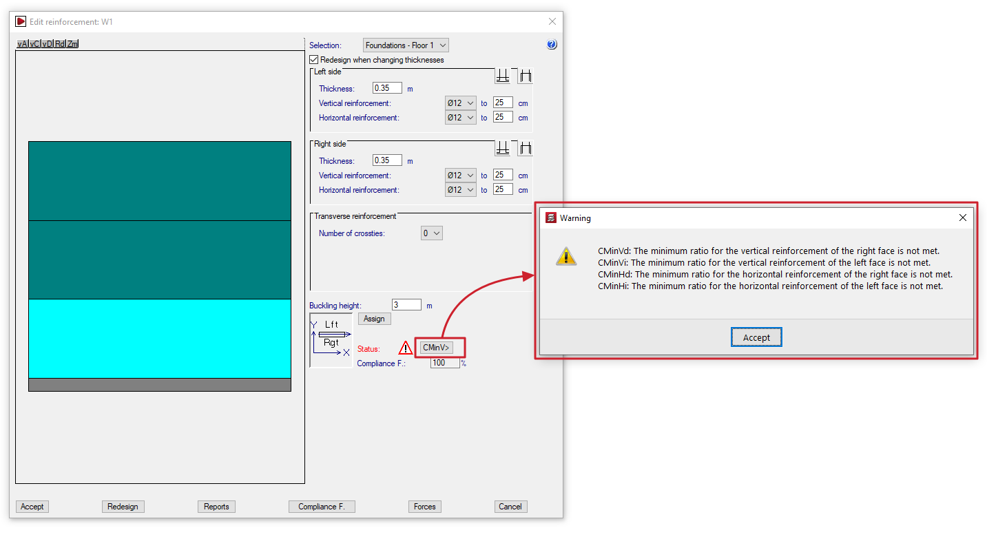
Checking the status of the wall
In the "Status" section, the program alerts the user to situations such as the following in the section of wall being examined, so that the user can assess them and/or take steps to correct them:
- If the prohibited symbol appears, the concrete section is failing due to oblique compression, and the calculated safety factor falls short of the required value.
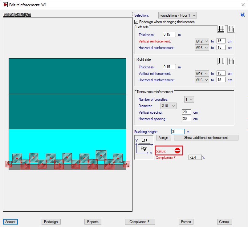
- If the warning symbol appears, which is less serious than the previous symbol, a button displaying an error code will be shown; clicking this button will open an information dialogue box. Possible warning scenarios include the following, which cover various regulatory breaches.
- If the concrete section or thickness is insufficient:
- Ee: The thickness is insufficient due to slenderness error.
- Er: There is no lever arm for the determination of the reinforcement. Increase the thickness or reduce the covers..
- If the reinforcement used is of a smaller size than required or has a diameter below the minimum:
- CMinVd: The minimum ratio for the vertical reinforcement of the right face is not met.
- CMinVi: The minimum ratio for the vertical reinforcement of the left face is not met.
- CMinHd: The minimum ratio for the horizontal reinforcement of the right face is not met.
- CMinHi: The minimum ratio for the horizontal reinforcement of the left face is not met.
- CMinT: The minimum geometrical ratio for the transverse reinforcement is not met.
- DMinT: The diameter of the transverse reinforcement is smaller than the minimum.
- if the required transverse reinforcement has not been defined, or if the spacing of the longitudinal bars it ties has been defined incorrectly:
- Ai: No transverse reinforcement has been provided, but it is necessary for the tying of vertical bars by Code.
- At: All vertical bars must be tied to the transverse reinforcement.
- SepSim: No transverse reinforcement has been installed, but the code requires the vertical bars to be tied together.
- If the concrete section or thickness is insufficient:
Wall compliance factor
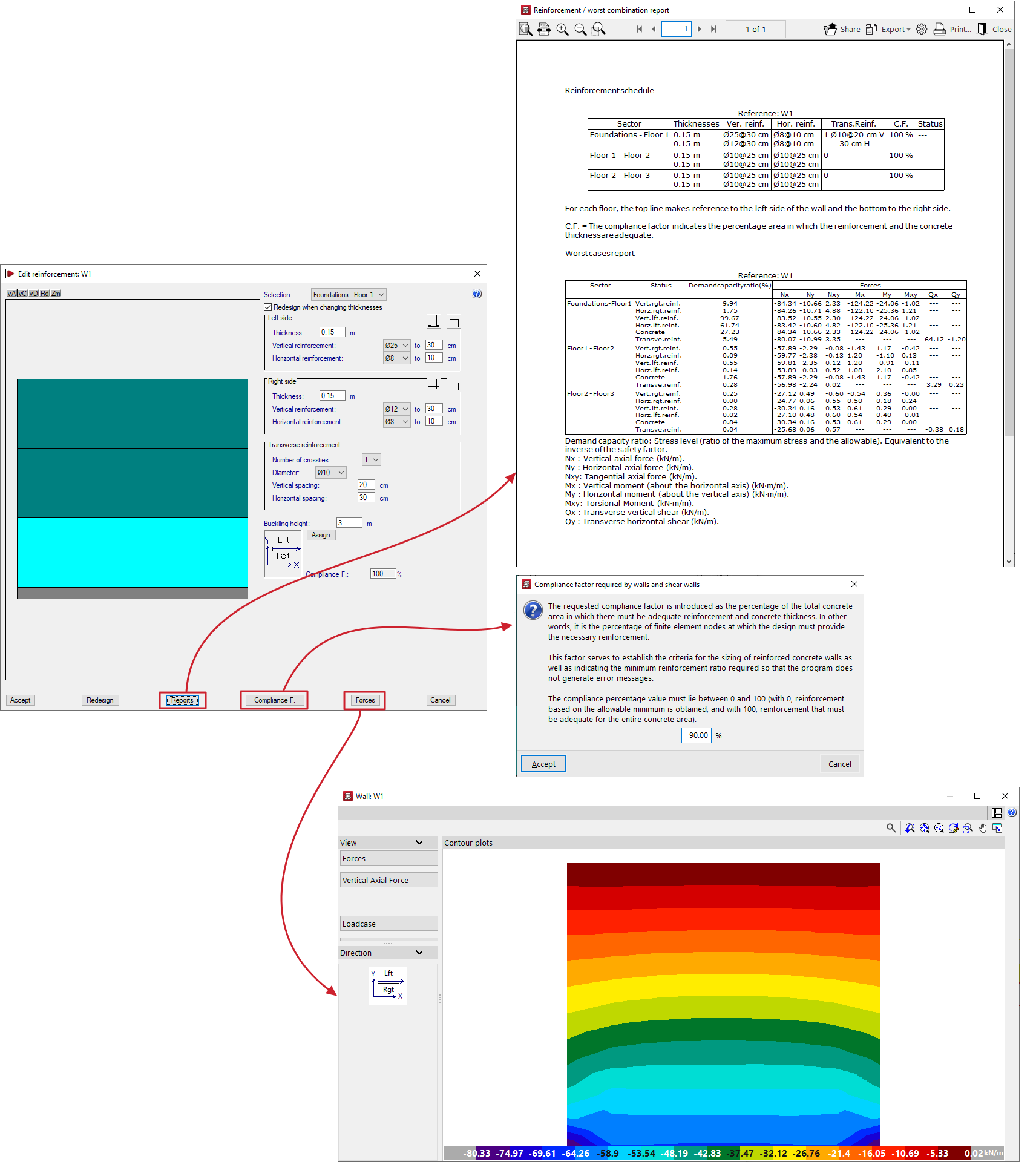
The "Compliance factor" field displays the calculated compliance factor, i.e. the percentage of nodes in the section under review that comply with the specified configuration.
If the calculated compliance factor is less than 100%, areas marked with red squares will appear on the wall diagram, indicating that localised reinforcement is required.
The required compliance factor can be changed using the relevant option at the bottom of the wall editing window.
| Note: |
|---|
| The required compliance factor is defined as the percentage of the total area of the concrete enclosure in which the specified reinforcement and thickness must be sufficient. This factor is used both to establish the design criteria for walls and to determine the minimum area in which a reinforcement arrangement is valid, thereby reducing the number of error messages generated. The percentage value must be between 0 and 100: 0% results in minimum reinforcement, and 100% results in reinforcement that complies throughout the entire concrete space. |
Additional options
The options at the bottom of the window allow you to perform the following actions:
- Accept
Accepts the changes made and exits the wall editing window. - Redesign
Allows you to rebuild and redesign the wall if changes are made to the thicknesses or the required compliance factor. - Reports
Allows you to generate a "Reinforcement schedule" (which includes thicknesses, the compliance factor and the status) and a "Worst cases report" (axial, bending, shear and torsional) for the concrete and each reinforcement bar in each section of the wall (including the demand capacity ratio or the ratio of maximum stress to allowable stress). - Compliance factor
Allows you to change the required compliance factor. If this value is changed, you must then redesign the wall using the relevant button, after which the program will calculate and display a new compliance factor. - Forces
This opens a window displaying the forces in the wall, similar to the one that appears when you select the "Force distribution in shear walls and walls" option from the "Envelopes" menu. - Cancel
Discards the changes made and exits the wall editing window.
CYPECAD - Designing concrete block walls
The reinforcement for concrete block walls is edited using the "Edit walls" option in the "Beams/Walls" menu on the "Results" tab.
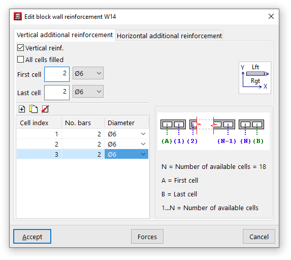
When you click on this option and select a concrete block wall in the model, the "Edit block wall reinforcement" window will open, featuring two tabs: "Vertical reinforcement" and "Horizontal reinforcement".
Vertical reinforcements
Vertical reinforcement bars are placed in the various cells of the block wall, for which they must be embedded.
To indicate the presence of this reinforcement, you must first tick the "Vertical reinforcement" box in the "Vertical additional reinforcement" tab.
Later on, you can enable the "All cells filled" option to take this condition into account in the wall.
You must specify the number of bars and their diameter for both the "first cell" and the "last cell" of the wall.
Finally, the table on the left allows you to optionally enter reinforcements in the remaining cells:
- On the right, the program will display a generic diagram of the wall. Below this, the "Number of available cells" in the wall is shown, numbered from 1 to N (excluding the first and last cells), whilst the first and last cells are labelled separately with the letters A and B.
- In this way, you can add reinforcement to the various cells by entering them into the table and specifying the "Cell index", along with the number of bars and their diameter.
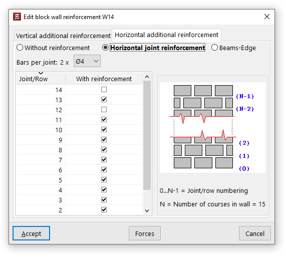
Horizontal reinforcements
Horizontal reinforcement consists of tie beams or belt beams placed at the various joints or courses of blocks in the wall.
On the "Horizontal additional reinforcement" tab, you can select one of the following three options:
- "Without reinforcement", if you do not wish to include horizontal reinforcement;
- "Horizontal joint bars", in which case reinforcement bars consisting of two bars per joint with the specified diameter shall be provided;
- or "Beams-Edge", in which case beam-type reinforcements consisting of four longitudinal bars of the specified diameter, tied together by stirrups of the specified diameter and spacing, shall be provided.
The table on the left allows you to add horizontal reinforcement bars to the various joints or courses of the wall:
- On the right, the programme will display a generic diagram of the wall. Below this, the "Number of courses in the wall" (N) is shown, along with the "Numbering of joints/courses" indexed from 0 to N-1. The base of the wall corresponds to joint number 0, whilst the joint between the penultimate and final courses is number N-1.
- This allows you to add reinforcement to each "Joint/Row" by ticking the "With reinforcement" box in the row corresponding to its number.
Results for wall openings
The "Wall openings" option, located within the "Beams/Walls" menu on the "Results" tab, allows you to view and modify the reinforcement applied by the program to wall openings.
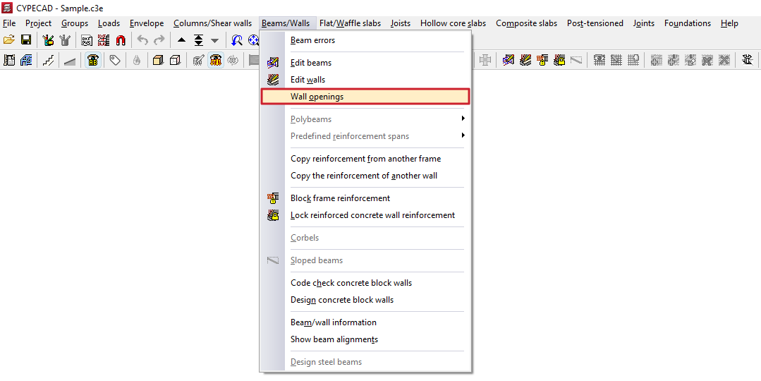
Clicking on this option opens the "Wall openings" window, which contains a menu with the following tools:
- Edit
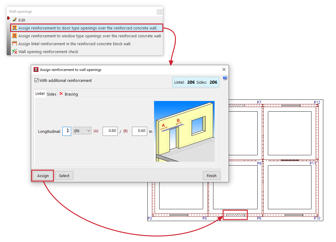
- Assign reinforcement to door-type openings over the reinforced concrete wall
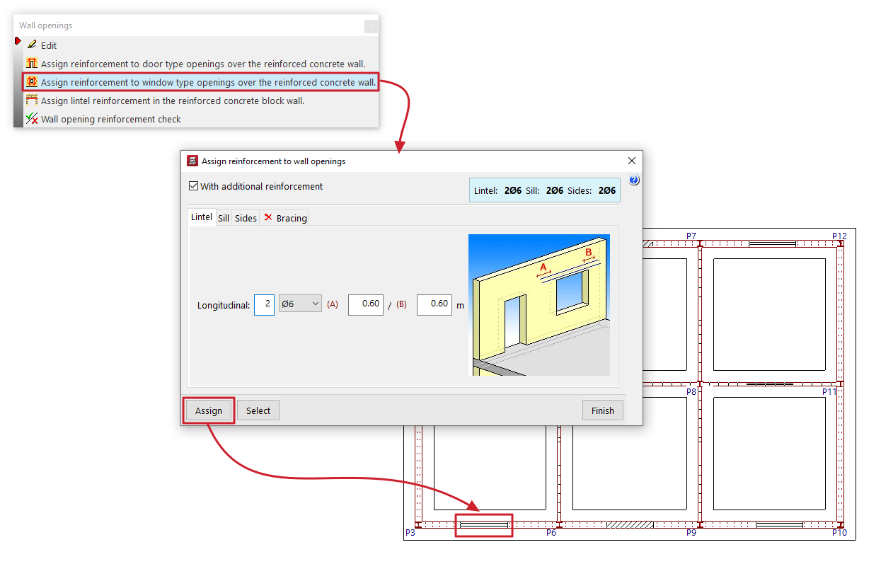
- Assign reinforcement to window-type openings over the reinforced concrete wall
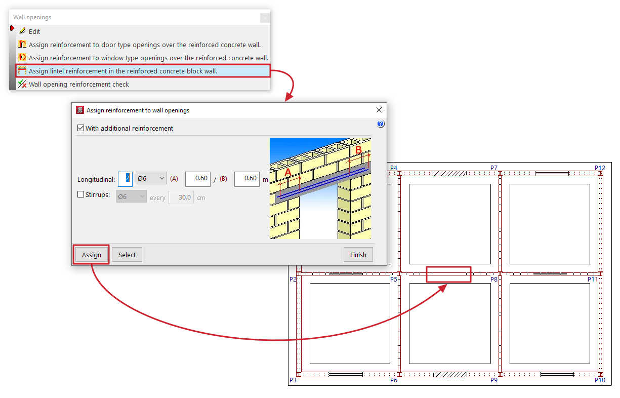
- Assign lintel reinforcement in the reinforced concrete block wall
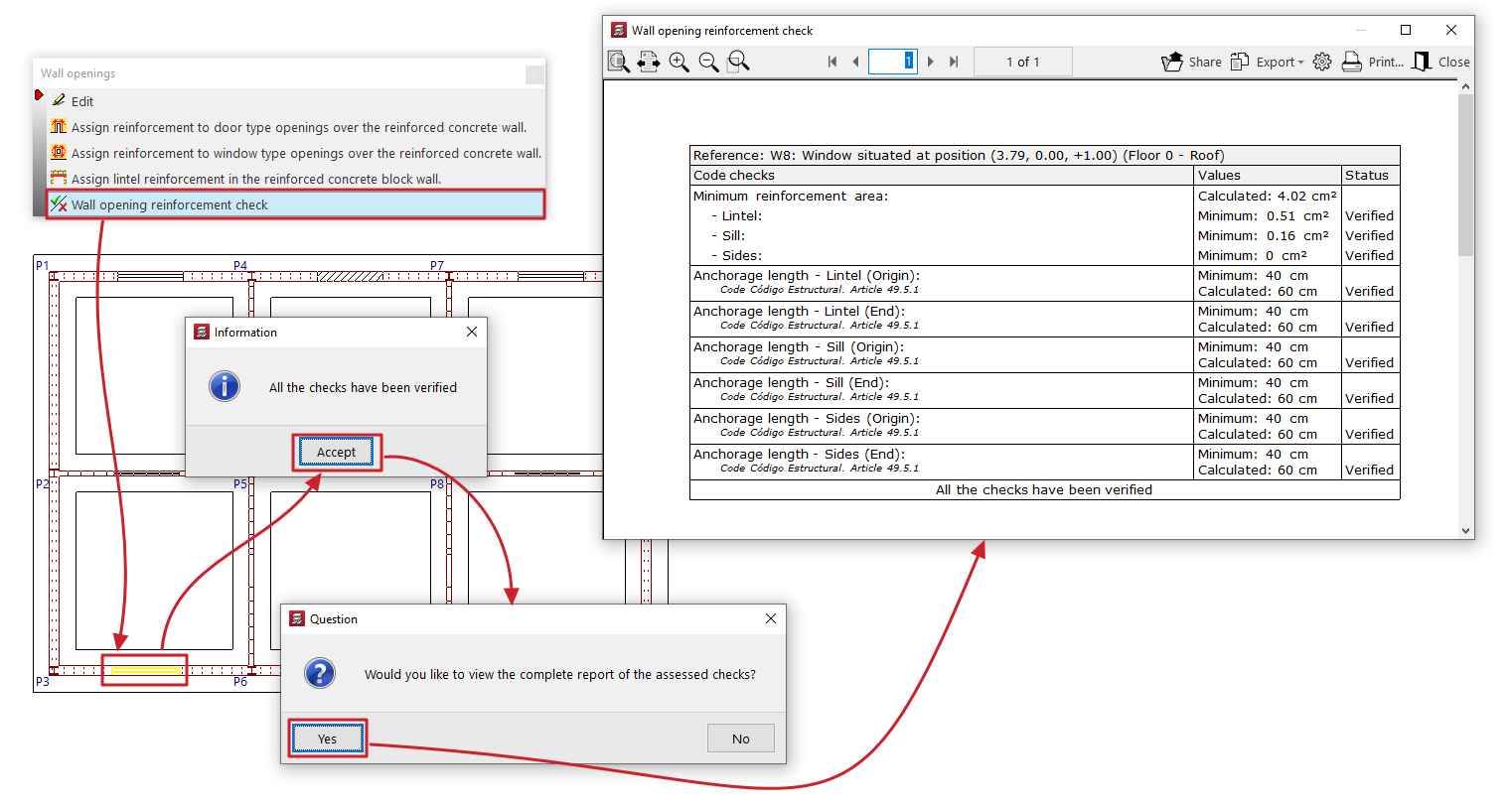
- Wall opening reinforcement check
Each of these features is described below:
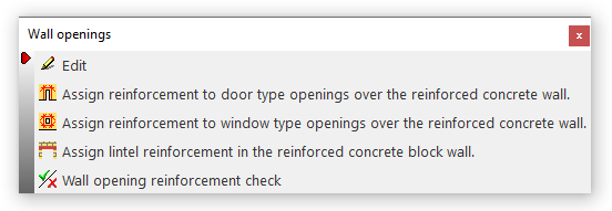
Edit
Allows you to edit the reinforcement mesh placed around the perimeter of the opening in the wall.
When you click on the option, the "Window" or "Door" panel opens, depending on the type of wall that is open.
First of all, you will need to specify whether there is a "Reinforcement the same for all floors of the group" or "Different reinforcement on each floor" by selecting the floor to be edited from the drop-down menu.
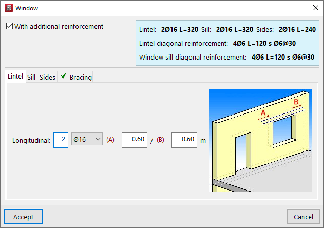
Next, the "With additional reinforcement" checkbox is selected if reinforcement bars are present around the perimeter of the opening. This enables the editing of the reinforcement in the lower section, which varies depending on the type of wall in which the opening has been created.
The assembly process is summarised in a coloured box to the right of this panel.
The program also displays a help diagram on the right-hand side to identify the assembly being edited, as well as its definition parameters.
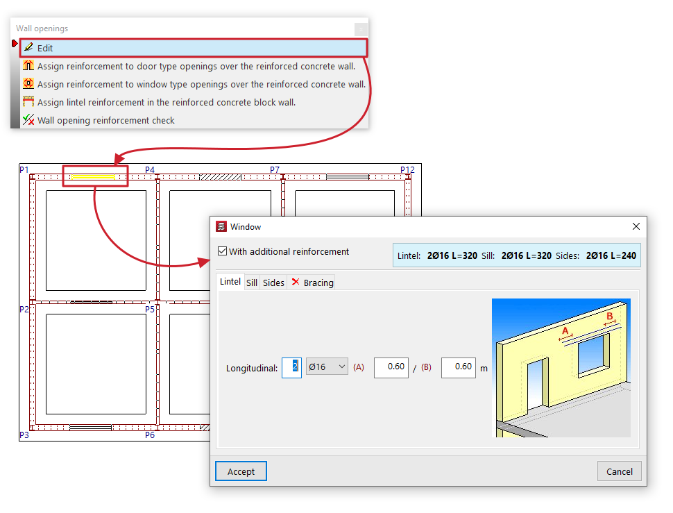
Reinforcement detailing for reinforced concrete walls, flat-tension walls and masonry walls
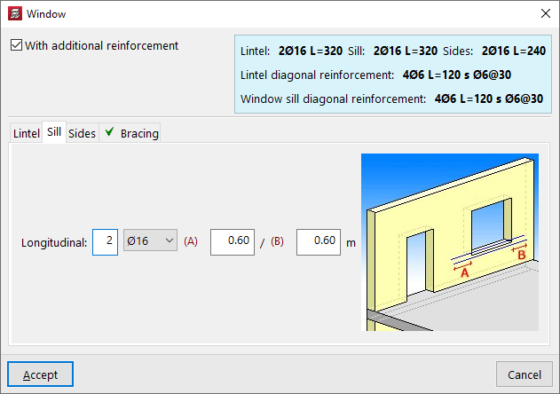
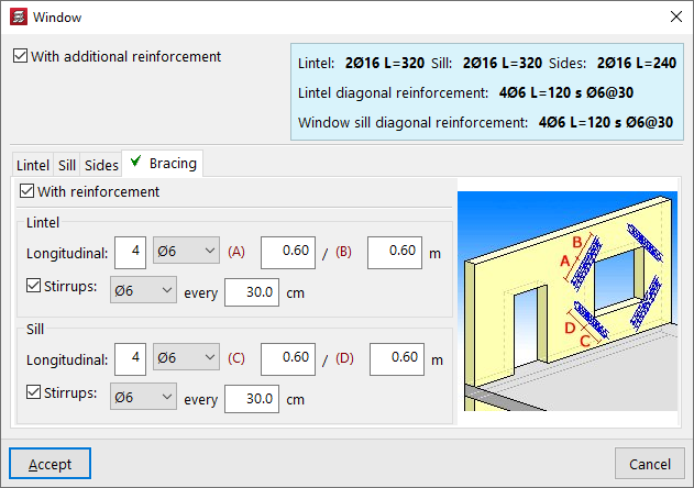
The components on these walls are edited using the tabs at the bottom: "Lintel", "Sill" (for windows), "Sides" and "Bracing":
- For the reinforcement of the "Lintel" (and for that of the "Sill" in windows), the number and diameter of the bars in the "Longitudinal" reinforcement are specified, as well as the distances "A" and "B" by which the reinforcement extends to the left and right beyond the edge of the opening.
- For the reinforcement of the jambs or "Sides", the number and diameter of the bars in the "Longitudinal" reinforcement are specified, as well as the distances "A" and "B" by which the reinforcement extends at the bottom and top beyond the edge of the opening.
- To add reinforcement to the "Diagonals", tick the "With reinforcement" box; then, for both the "Lintel" and, where applicable, the "Sill", specify the number and diameter of the "Longitudinal" reinforcement bars, as well as the distances "A" and "B" by which the reinforcement extends beyond the corner of the opening; finally, tick the bottom box to indicate the presence of "Stirrups", their diameter and spacing.

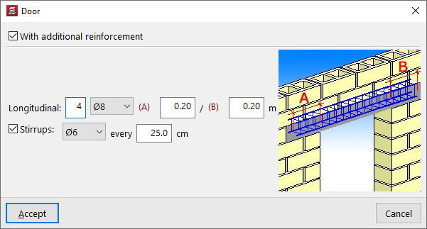
Reinforcement detailing for concrete block walls
You can add reinforcement to the lintel of openings in concrete block walls.
To do this, specify the number and diameter of the "Longitudinal" reinforcement bars, as well as the distances "A" and "B" by which the reinforcement extends to the left and right beyond the edge of the opening; finally, tick the box at the bottom to indicate the presence of "Stirrups", their diameter and spacing.
Assign reinforcement to door-type openings over the reinforced concrete wall
This option is available if openings have been created in walls of the "Reinforced concrete wall", "Masonry wall" or "Plane stress walls" type.
Clicking on this option opens a reinforcement editing panel for the opening, identical to the one that appears when using the "Edit" option. In this case, you can define a reinforcement for "Door" openings in the panel and then click "Assign" to apply it to the doors opening onto this type of wall selected in the current floor plan group. It is also possible to use the "Select" option in the panel to extract information from a selected opening on the floor plan.
Assign reinforcement to window-type openings over the reinforced concrete wall
This option is available if openings have been created in walls of the "Reinforced concrete wall", "Masonry wall" or "Plane stress walls" type.
Clicking on this option opens a reinforcement editing panel for the opening, identical to the one that appears when using the "Edit" option. In this case, you can define a reinforcement for "Window" openings in the panel and then click "Assign" to apply it to the windows in this type of wall selected in the current floor group. It is also possible to use the "Select" option in the panel to extract information from a selected opening on the floor plan.
Assign lintel reinforcement in the reinforced concrete block wall
This option is available if openings have been created in walls of the "Concrete block wall" type.
Clicking on this option opens a reinforcement editing panel for the opening, identical to the one that appears when using the "Edit" option. In this case, you can define a reinforcement for openings in the panel and then click on "Assign" to apply it to the openings in this type of wall selected in the current floor plan group. You can also use the "Select" option in the panel to extract the information from a selected opening in the floor plan.
Wall opening reinforcement check
This option allows you to select a wall opening on a floor plan and display on screen the list of checks carried out on its reinforcements, as well as their compliance status.
These include checks on the minimum reinforcement area or the minimum anchorage length of the bars, depending on the selected standards.
This report can be printed or exported in various formats.
| Note: |
|---|
| If the position or dimensions of a wall opening are changed after the last analysis has been carried out, it will not be possible to check the reinforcement for the opening. However, even if the opening has been added or modified since the last calculation was performed, the program allows you to edit and draw its reinforcement on the drawings. If you wish to dimension and check the wall taking into account the opening’s reinforcement, the structure must be recalculated. |
Polybeams
The "Polybeams" menu, within the "Beams" menu of the "Beam input" tab or the "Results" tab, allows you to create and manage polybeams.
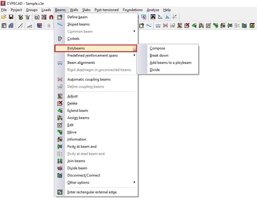
A polybeam is a set of consecutive beams without intermediate columns that constitute a group for the purposes of editing their section or removing them.
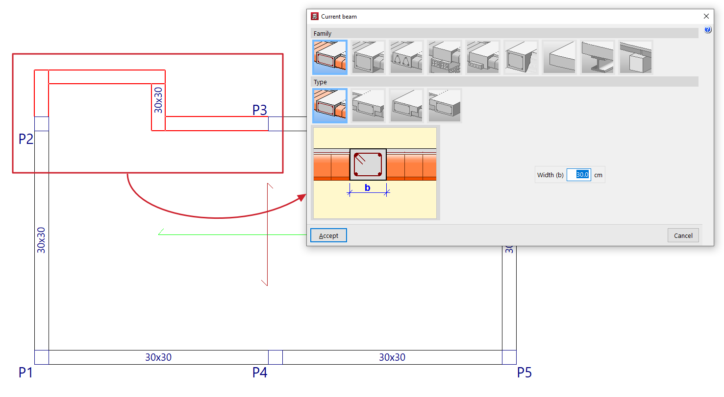
Thus, any geometric change (for example, from "Beams > Edit") made to one of the beams is applied to all the beams that form the polybeams.
Similarly, deleting the polybeam (using "Beams > Delete") causes the entire set of beams that constitute it to be deleted. However, the reinforcement of each beam in the set may be different.
The menu offers the following options:
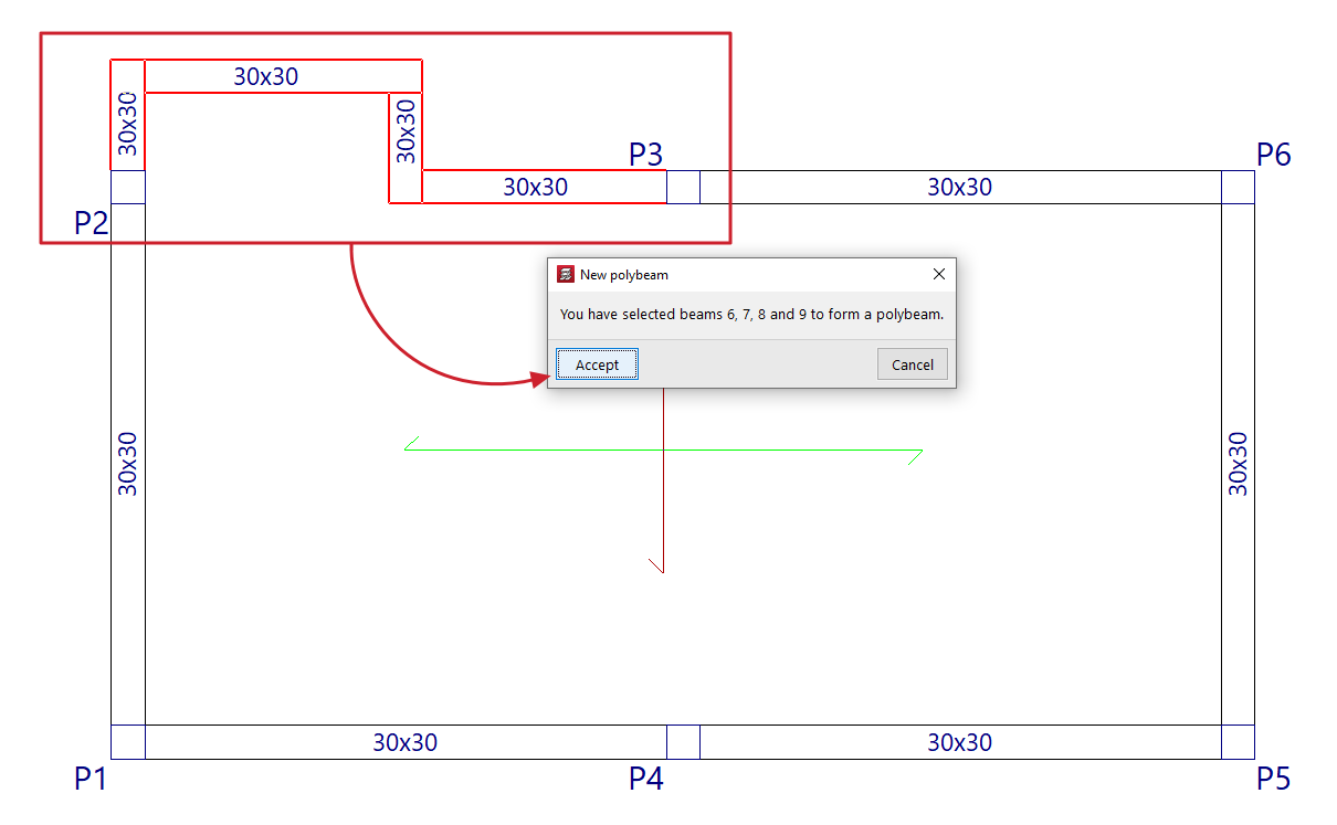
Compose
The "Compose" option allows you to create a new composite beam. To do this, select consecutive beam sections with the left mouse button and, when finished, confirm the operation with the right mouse button. The program will notify you of the beams that have been selected in a pop-up window, indicating their reference on the screen. When you accept this notification, the composite beam is created.
Break down
The "Break down" option allows you to ungroup all the beams of one or more previously created polybeams. To do this, select the polybeams to be broken down with the left mouse button or mark a capture area on the screen.
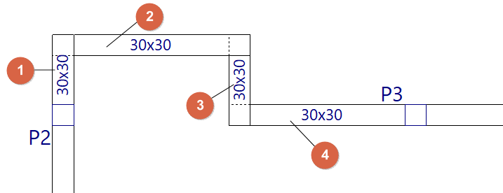
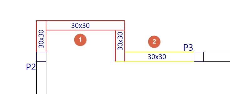
Add beams to a polybeam
The "Add beams to a polybeam" option allows you to add one or more beams to an existing polybeam. To do this, select the polybeam (1) and then the beam or beams you want to add to it (2), confirming the operation with the right mouse button. The program will notify you of the beams that will be added to the polybeam, indicating their reference on the screen. When you accept the notification, the polybeam is updated with the addition of the selected beams.
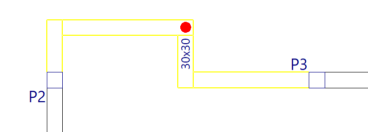
Divide
The "Divide" option allows you to split a polybeam into several polybeams or into separate beams at the point selected with the left mouse button. This option can also be useful for ungrouping one of the two end beams of a polybeam.
Predefined reinforcement spans in beams
The "Predefined reinforcement spans" menu, within the "Beams" menu of the "Beam input" tab or the "Results" tab, allows you to create or delete predefined reinforcement sections in multi-beams.
A predefined reinforcement section in the set of beams that make up a composite beam is one in which the positive and negative reinforcement is continuous.
| Note: |
|---|
| This will be possible provided that the analysed length of the steel bar does not exceed the "Maximum length of a bar" set in the general options of the program. |
The menu offers the following options:
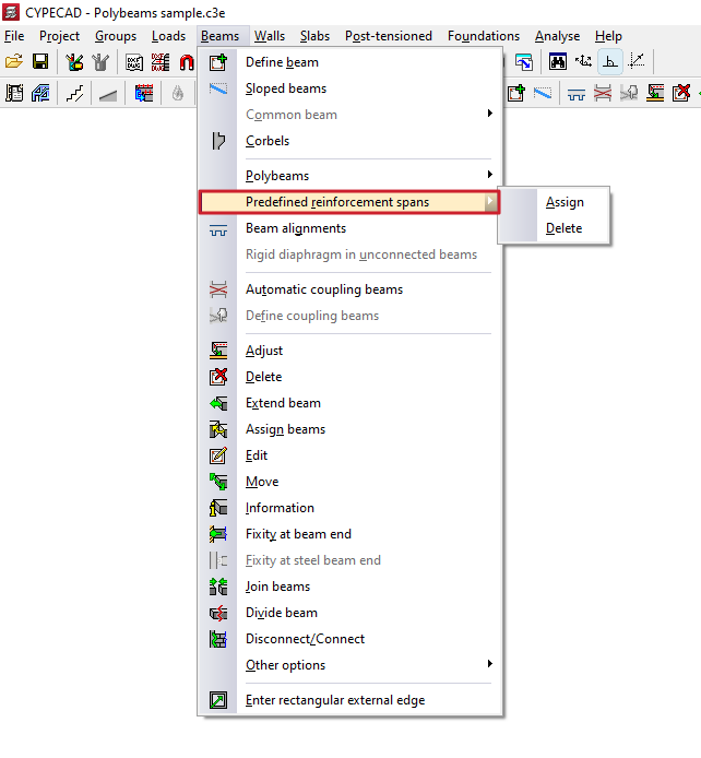
Assign
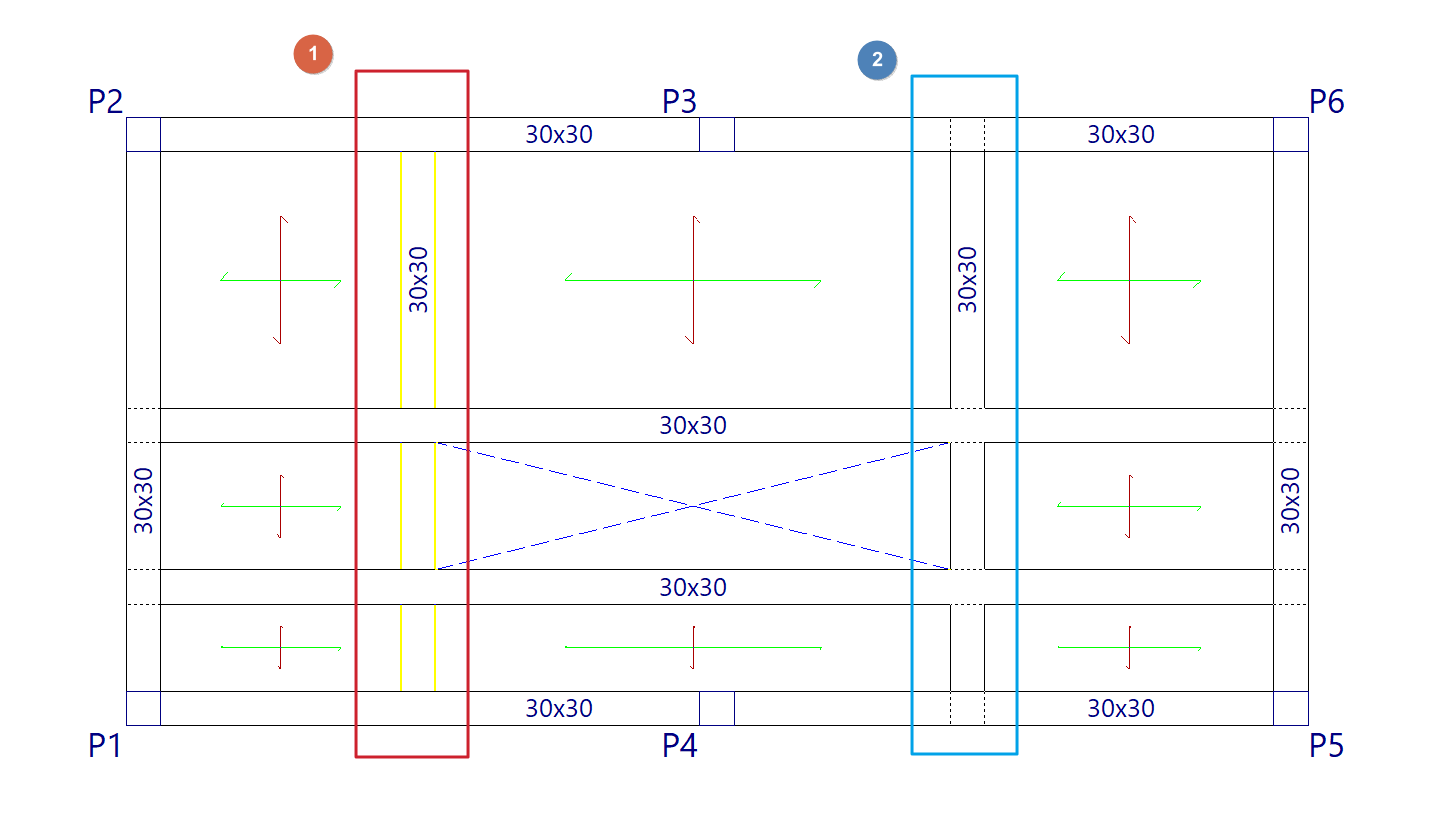
The "Assign" option allows you to create a predefined reinforcement section in each of the multi-beams that are subsequently selected, either with the left button or by means of a capture area.
Each poliviga selected in this way constitutes an independent, predefined reinforcement section.
In this way, when analysing and assembling the frames, the program will apply continuous reinforcement to each predefined reinforcement section created.
Delete
The "Delete" option allows you to ungroup the reinforcement of all beams in a predefined reinforcement section created previously. After using this option, you will need to re-analyse or re-reinforce the frames to generate the reinforcement of the beams independently.
Copying frame and wall reinforcements
The following options in the "Beams/Walls" menu on the "Results" tab allow you to copy structural models between frames or between walls:
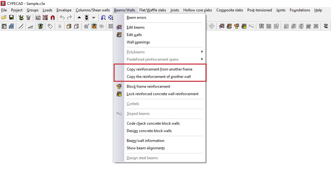
Copy reinforcement from another frame
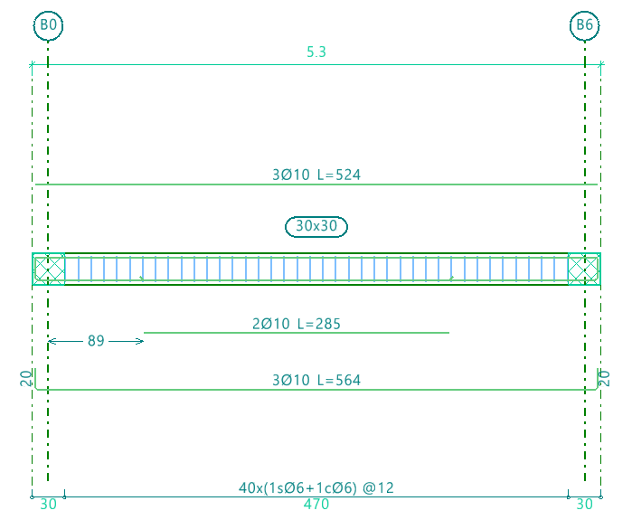
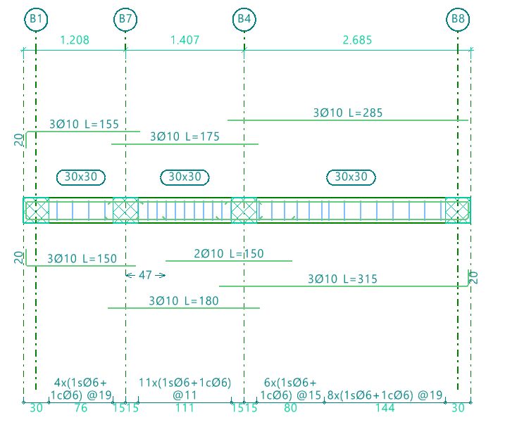
This option allows you to copy the layout of one portal onto another portal. The two portals must have the same number of spans:
- For the longitudinal reinforcement and the first layer of positive elements, the diameter, number and length of each bar’s end are copied relative to the support axis.
- For the remaining longitudinal bars, the diameter, number and length of the bars are copied.
- For the stirrup, the diameter, spacing and length of the reinforcement are copied.
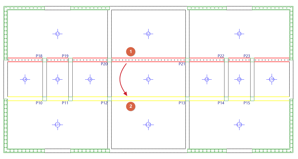
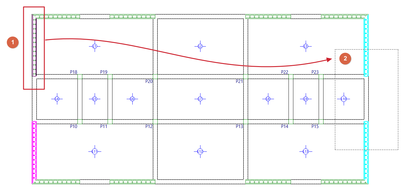
The procedure for copying the layout between frames located on the same group of floors is as follows:
- Go to the floor where the frames are located.
- Select the "Copy reinforcement from another frame" option.
- Left-click to select the frame you wish to copy (1).
- Use the left mouse button to select the destination span or span (2) to which you wish to assign the selected reinforcements.
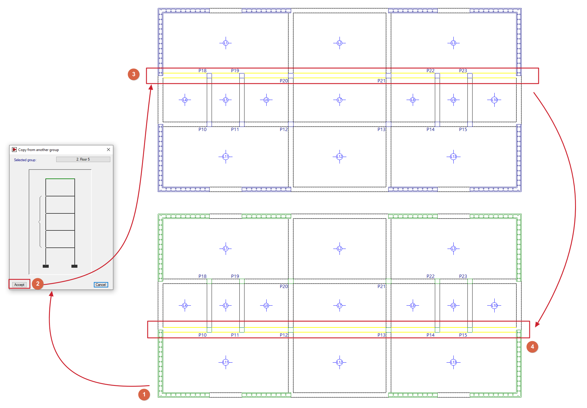
Furthermore, the procedure for copying the reinforcement between frames located on different floor levels is as follows:
- Go to the floor where the destination frame is located (1).
- Select the "Copy reinforcement from another frame" option.
- Click the right mouse button and, in the dialogue box that appears, select the floor on which the portal containing the information to be copied is located (2).
- The program will then be positioned on the selected floor. Here, use the left mouse button to select the portal to be copied (3).
- The program immediately returns to the starting floor. Here, use the left mouse button to select the destination span or spans (4) to which you wish to assign the selected reinforcements.
| Note: |
|---|
| After making the copy, we recommend that users check the beam assembly onto which the copy has been made, to ensure that the quantities specified are not lower than those required, as the program does not flag this issue at the time of copying. Copying the reinforcement between frames does not mean that a single frame will appear in the beam drawing. This will only happen when the geometry of the copied frames is exactly the same. |
Copy the reinforcement from another wall
This option allows you to copy the structure of one wall onto another wall. The procedure is as follows:
- Go to the floor where the walls are located.
- Select the "Copy reinforcement from another wall" option.
- Left-click on the wall to be copied (1).
- Left-click to select the destination wall or walls (2) to which you wish to assign the selected reinforcement, or use a selection area to select them. Walls with the reinforcement already copied will be highlighted in magenta.
Grouping frames
The following options in the "Beams/Walls" menu on the "Results" tab allow you to manage frame groupings.
| Note: |
|---|
| These options are only available for codes that do not allow the use of the advanced beam editor. For projects using modern codes, you can use the options in the "Beam alignments" menu under the "Beams" menu in the "Beam input" tab, or the options for copying reinforcement between frames in the "Beams/Walls" menu in the "Results" tab. |
Frame groupings allow you to consolidate the results obtained for several similar frames and make them easier to edit. Thus, modifying the standard frame automatically affects the grouped frames, and vice versa. Furthermore, the beam plan will show a single frame per group, listing all the references belonging to the grouped frames (frame numbering, bracing, columns, beams, etc.).
To avoid errors when grouping frames, they must have the same number of bays.
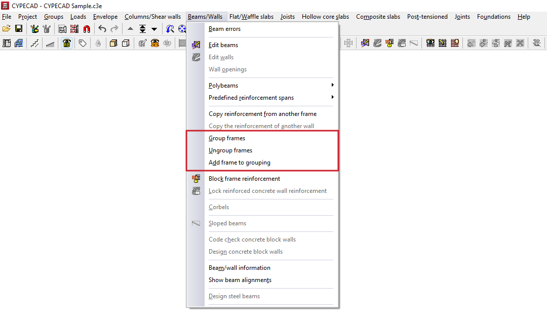
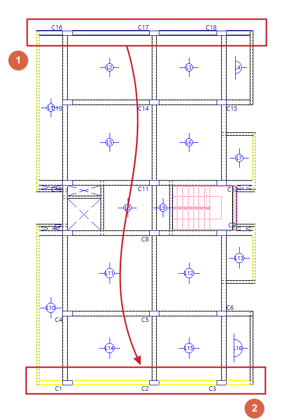
Group frames
This option allows you to group frames together.
To do this, after clicking on this option, use the left mouse button (1) to select the type of frame (which will be highlighted in blue) and then (2) the frames to be grouped (which will be highlighted in green). When selecting the frame to be grouped, the program will display a warning message if it cannot be grouped and the reason why. Clicking the right mouse button and accepting the dialogue box that appears creates the group.
The frame type will appear in the drawing, in the reports, and in the reinforcement editor. Grouped frames are treated as identical to the type, except for their references.
| Note: |
|---|
| When grouping frames, no checks are carried out to ensure compliance within the grouped frames; therefore, these must be similar in terms of span and reinforcement. |
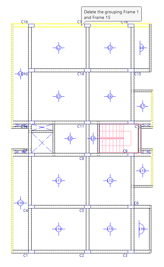
Ungroup frames
This option allows you to undo a previously created group of frames, restoring them to independent frames.
When you use this option and hover the cursor over a group of frames, the program will display a tooltip showing the references of the frames in the group. Clicking the left mouse button will ungroup them.
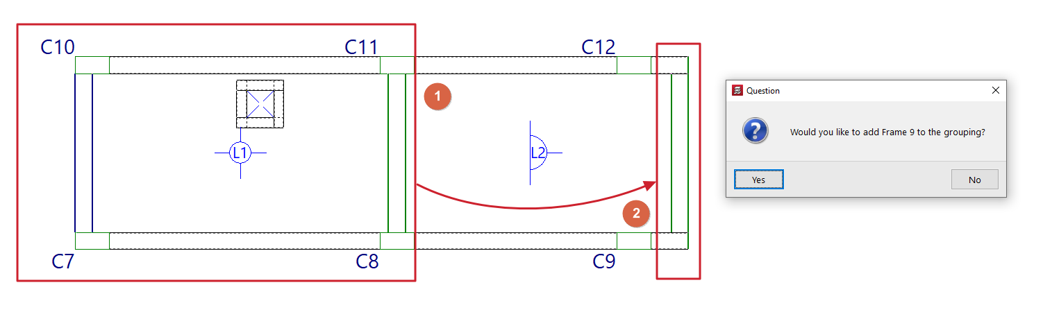
Add frames to group
This option allows you to add new frames to an existing group.
To do this, after clicking on the option, select a grouped frame (1) and then one or more ungrouped frames that you wish to add to the group to which the first selected frame belongs (2). Right-click and confirm the dialogue box that appears to add them to the group.
Locking frame reinforcements and reinforced concrete walls
The following options in the "Beams/Walls" menu on the "Results" tab allow you to lock the reinforcement for frames and reinforced concrete walls, respectively.
When you lock the reinforcement, you can reanalyse the structure whilst retaining the reinforcement of the selected elements.
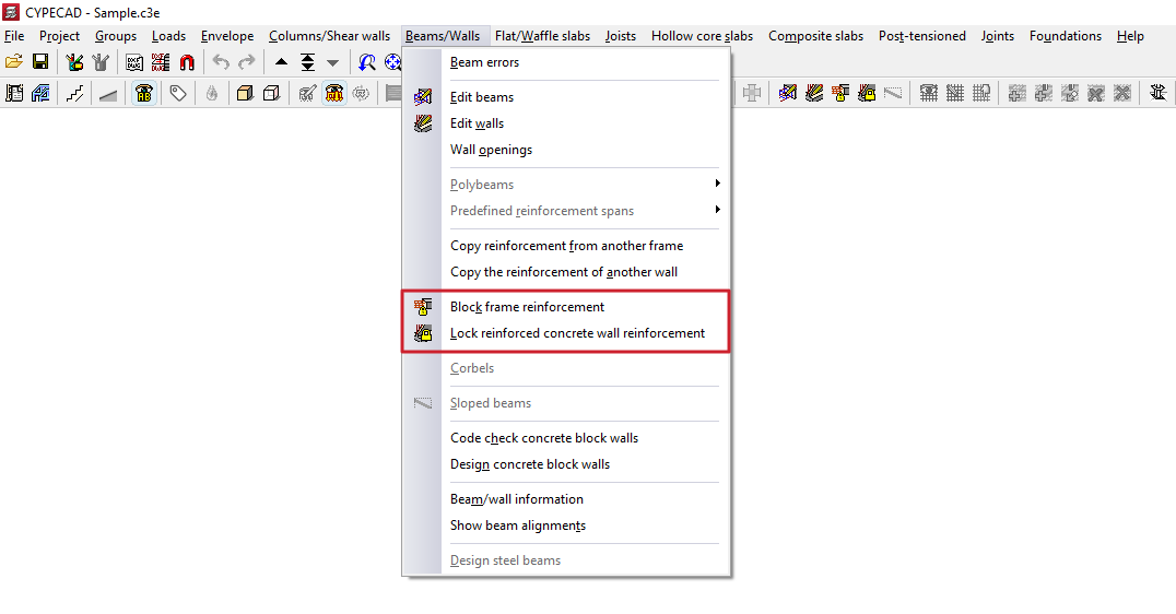
Lock portal frames
This option allows you to lock the reinforcement for the selected frames to prevent the program from modifying them during subsequent redesigns.
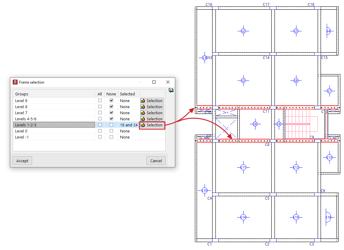
When you click on the option, the "Frame selection" window opens:
- Here, in each of the "Groups" of floors, you can lock "All" or "None" of the doors on that floor by ticking the relevant boxes.
- If desired, by clicking the "Selection" button, you can select the frames you wish to lock on each floor one by one by left-clicking on them (clicking again on a previously selected frame deselects it and therefore unlocks it). Clicking the right button returns you to the "Frame selection" window.
- The "Selected" column will list the references of the frames selected in each group, or will indicate whether they are "All" or "None".
- After clicking "Accept" in this window, the program will lock the reinforcement for those frames.
It is also possible to lock or unlock a portal frame using the relevant option in the beam editor, which can be accessed via "Beams/Walls > Edit beams".
| Note: |
|---|
| The following points should be considered when using the “Lock frame reinforcements” option: - This option allows you to retain any manual modifications made to the reinforcements of the frames, even if the structure is redesigned. It can therefore be used to retain the reinforcement of frames on floors that have not changed or on those where the modifications made are not significant. - After redesigning, locked frames that do not pass the relevant checks will be highlighted in the colour configured for beam errors. In these cases, the user must review the frames with errors (the "Results" tab, "Beams/Walls > Edit Beams”), check whether the errors are significant, and decide whether the problem can be resolved by slightly modifying the reinforcement or whether it is necessary to unlock the frame and re-reinforce it. -Unlocked frames will be fully re-analysed when analysing the structure. During this process, the program performs all the checks required by the selected standard using the forces obtained in the last analysis. - The program offers two options for re-reinforcing unlocked frames: "Re-reinforce all frames", or "Re-reinforce frames with changes" (available in the "Beam Input" tab, "Analysis" menu). This latter option redesigns only the reinforcement of those unbound frames whose section has been modified. |
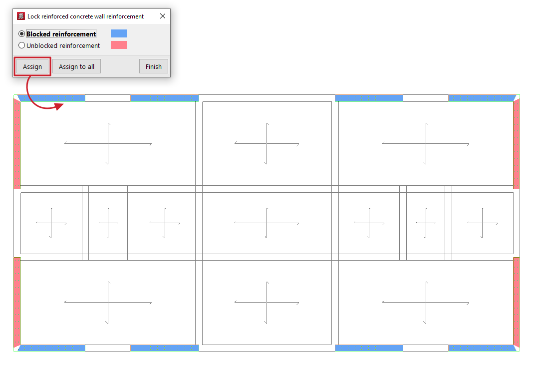
Lock reinforced concrete wall reinforcement
This option allows you to lock the reinforcement of selected reinforced concrete walls and flat-tension walls to prevent the program from modifying them in subsequent redesigns.
When using this tool, a dialogue box appears where you can select one of the following options: "Locked reinforcements" or "Unlocked reinforcements". In addition, the program will highlight the walls assigned to each condition in the floor plan using the corresponding colour.
To apply one of the two conditions, select it; then click on "Assign" and select the desired walls on the floor plan one by one or using a selection area. When you do this, they will change colour to indicate that the condition has been applied. Right-clicking returns you to the dialogue box. It is also possible to click on "Assign to all" to apply the selected condition to all visible walls on the floor plan. The "Finish" option allows you to complete the operation.
Options in the "Sloped beams" menu (the "Results" tab)
The "Sloped beams" option, within the "Beams" menu on the "Results" tab, allows you to view the analysis results for inclined beams, bracing diagonals and V-bracing.
This option is available if the job has been analysed.
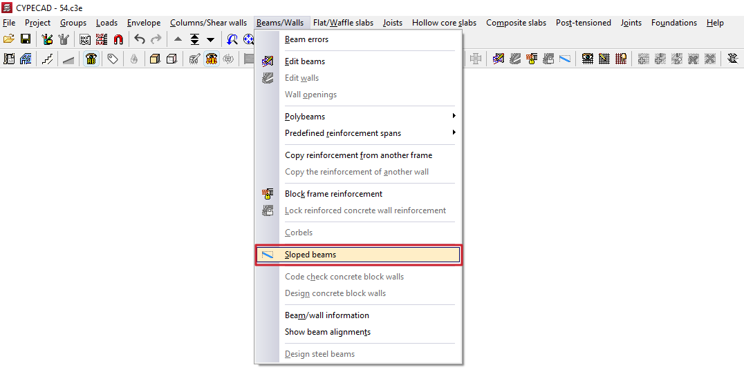
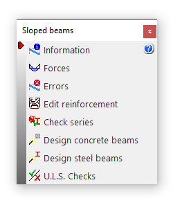
Clicking on this option opens the "Sloped beams" window, which contains a menu with the following tools:
- Information
- Forces
- Errors
- Edit reinforcement
- Check series
- Design concrete beams
- Design steel beams
- U.L.S. checks
Each of these features is described below:
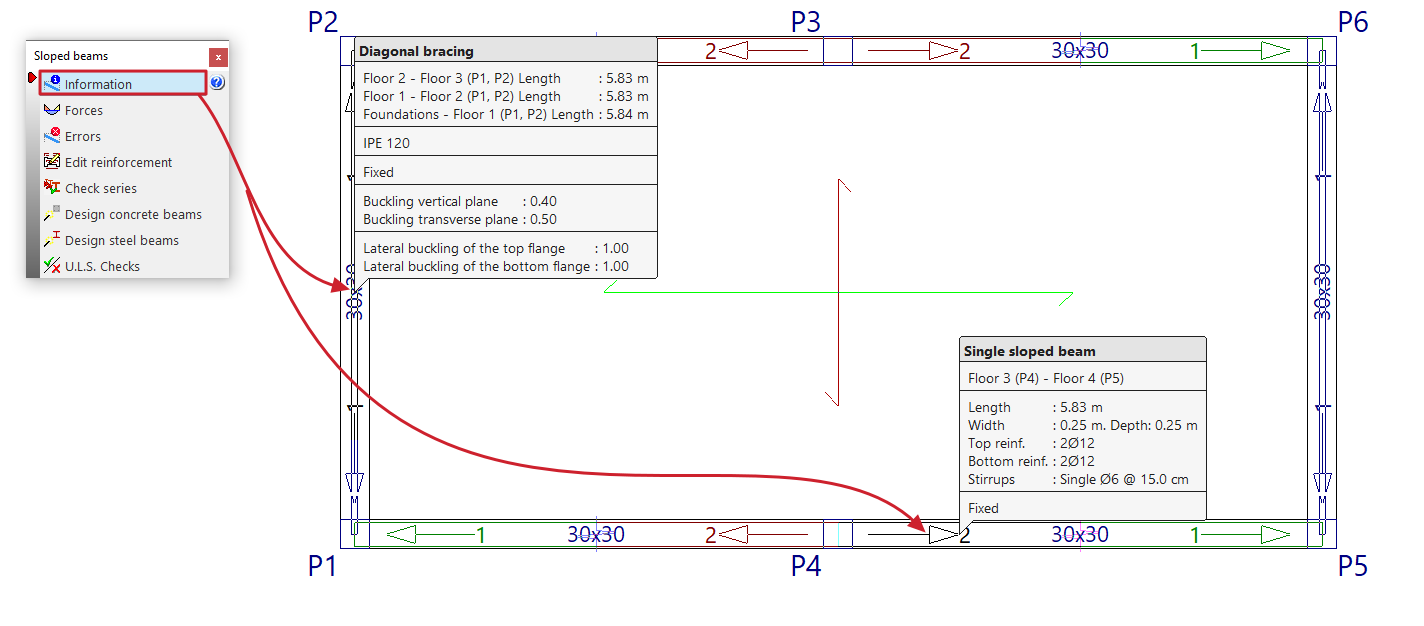
Information
Clicking the "Information" option displays information on screen about the sloped beams, bracing diagonals or V-bracing already entered. To do this, select the element you wish to view on the floor plan using the left mouse button, or enter the corresponding element number.
An information text box then appears, displaying details such as the element’s start and end tags, its length, section, and the other parameters entered in its editing panel.
If the structure has been structurally analysed, information on the bracing of single inclined beams is also included (“Upper bracing”, “Lower bracing” and “Strut bracing”).
This option is the same as the one available in the menu of the same name on the "Beam Input" tab.
Forces
The "Forces" option provides a list of efforts and results for the selected item.
The forces that can be listed include the "Axial force", the "Planar moment", the "Transverse moment", the "Planar shear", the "Transverse shear" and the "Torsion". To do this, you can tick the boxes with these names.
These results can be obtained for the "Number of points" of the beam entered in the corresponding field.
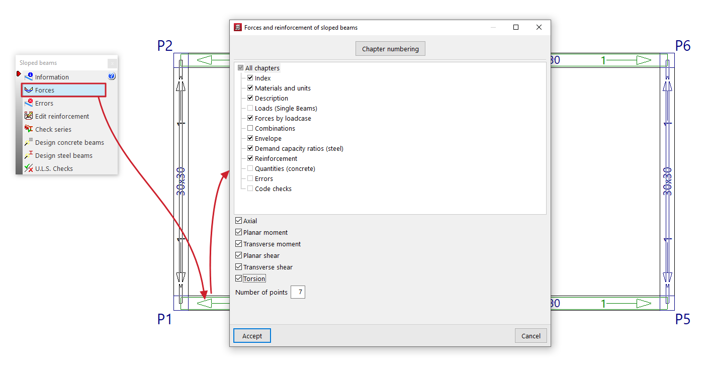
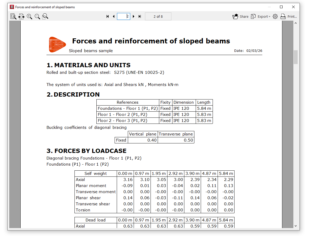
This list includes the materials, description, loads (for simple sloped beams), design forces, combination forces, force envelopes, demand capacity ratio (for steel sections), design results (or reinforcement results in the case of concrete beams), quantities (for concrete beams), design errors where applicable, and checks carried out.
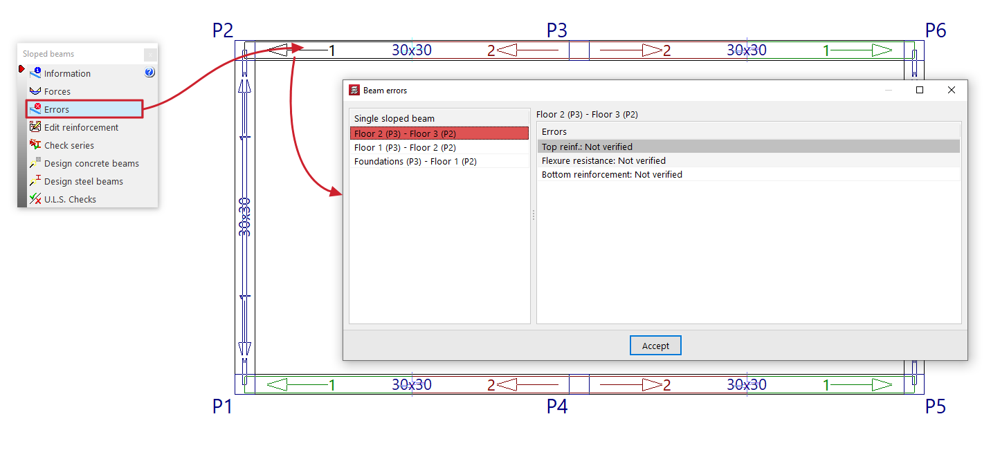
Errors
Sloped beams, bracing diagonals and V-bracing with analysis errors will be highlighted in red in the workspace.
The "Errors" option in this menu allows you to select one of these elements and display a list of errors on screen.
Edit reinforcement
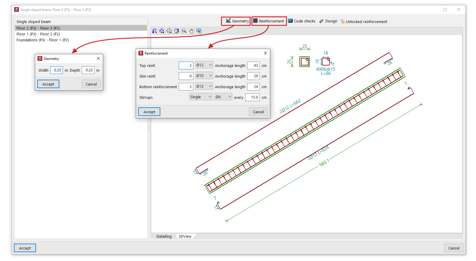
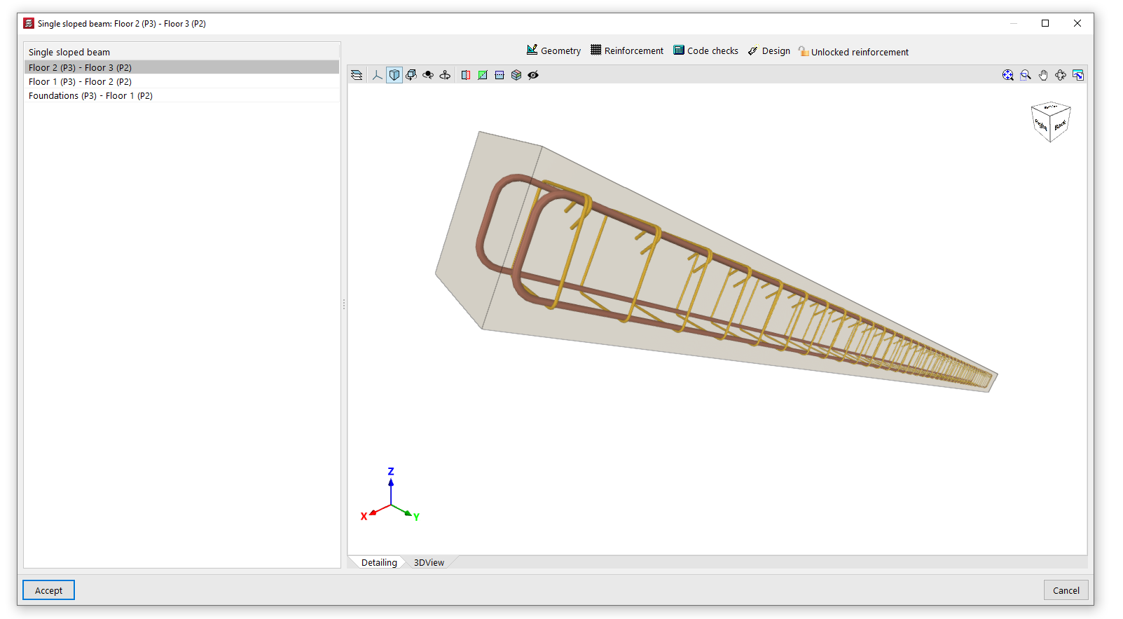
The "Edit reinforcement" option allows you to select a single sloped reinforced concrete beam and view and edit the reinforcement results from the analysis in an editing window.
This editing window has two tabs. The "Section" tab displays a view showing the longitudinal and cross-sectional views of the beam, indicating its dimensions and reinforcement, whilst the "3D View" tab provides a three-dimensional view of the beam with its reinforcement.
In addition, the program provides the following tools at the top of this window:
- Geometry
Allows you to modify the width and depth of the beam. Once modified, you can use the "Dimensioning" option to generate the reinforcement. - Reinforcement
Allows you to modify the number and diameter of the bars in the "Top reinforcement", the "Skin reinforcement" and the "Bottom reinforcement", as well as the type, diameter and spacing of the beam's "Stirrups". You can also modify the "Anchorage length" of the bars in each of the aforementioned reinforcement groups. Once modified, you can use the "Code checks" option to check the beam with the specified reinforcement. - Verification
This allows you to verify compliance with regulatory specifications in light of the changes made. Furthermore, you can display a list of these verifications on screen. - Structural analysis
Carries out a structural analysis of the beam to determine a reinforcement scheme that satisfies all the checks for the beam’s geometry and forces obtained in the analysis. - Locked reinforcement / Unlocked reinforcement
Allows you to lock the beam reinforcement so that the program does not modify it during the analysis and design process, or to unlock it if it has previously been locked.
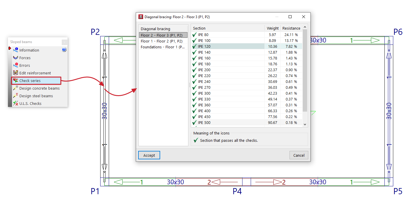
Check series
The "Check series" option allows you to select a sloped steel-section beam, bracing diagonals or V-bracing, and view the selected section—as well as the other sections in the same series—in the pop-up window during the design process.
For each "Section", an icon indicates whether it passes all the checks or not, along with its reference, "Weight" and the demand capacity ratio percentage of "Strength".
If you wish to use a specific section, select that section from the list and click "Accept".
Designing concrete beams
The "Design concrete beams" option redesigns all the sloped reinforced concrete beams in the project using the forces from the most recent analysis.
Designing steel beams
The "Reload steel beams" option re-analyses all sloped steel beams, bracing diagonals and V-bracing in the project using the loads from the most recent analysis.
You can do this "From the first section" in the series or "From the selected section" by selecting the relevant option in the pop-up window.
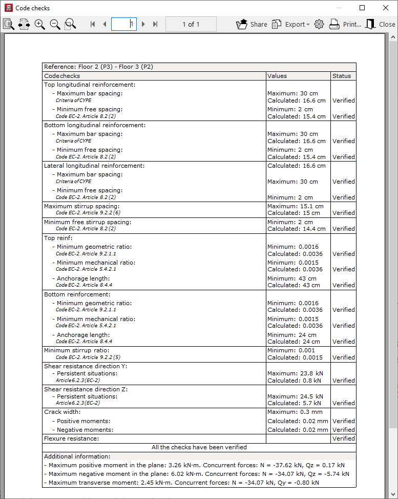
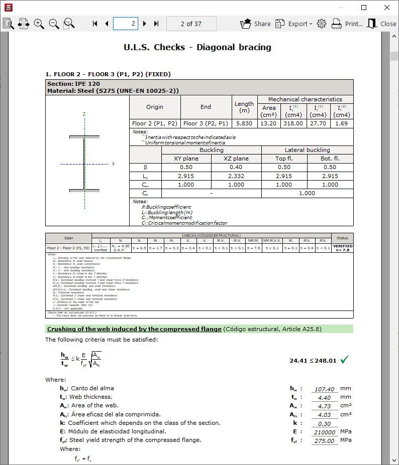
U.L.S. checks
Displays a document detailing the checks carried out on a sloped steel-section beam to verify the Ultimate Limit States corresponding to the selected standard.
Checking and designing concrete block walls
The following options in the "Beams/Walls" menu on the "Results" tab allow you to check and design concrete block walls, respectively.
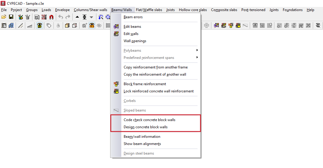
Code check concrete block walls
This option allows you to check whether the checks carried out on the concrete block walls have been passed.
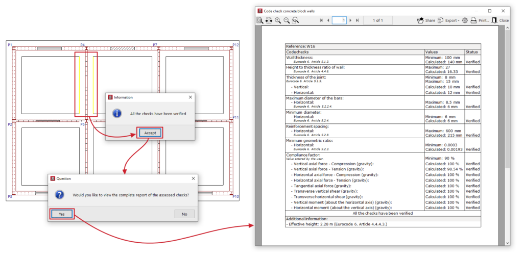
To do this, after clicking on the option, use the left mouse button to select the wall you wish to check. The program will indicate whether all the checks have been passed or whether any checks have failed.
Once you have accepted the dialogue box that appears, you can view on screen the list of checks carried out on the wall, including those relating to the wall’s geometry, reinforcement or compliance factor under various loads.
This report can be printed or exported in various formats.
Designing concrete block walls
This option allows you to redesign the reinforcement for concrete block walls without having to reanalyse the structure. This can be useful if minor changes have been made to the dimensions of these walls.
If you do this, any changes made to these structures based on the results of the previous design will be lost.
The forces used to design the reinforcement shall be those obtained from the most recent structural analysis carried out.
| Note: |
|---|
| Changes to the type of block used in the walls render the forces obtained in the last analysis invalid. For this reason, if you wish to ensure the accuracy of the results—particularly if significant changes have been made to the dimensions—we recommend that you reanalyse the job. |
Checking beam/wall information and beam alignments
The following options in the "Beams/Walls" menu on the "Results" tab allow you to view information about the beams and/or walls and to view the beam alignments, respectively.
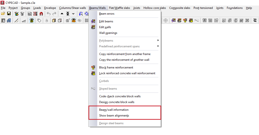
Beam/wall information
This option provides information on the properties and results of a beam or wall added to the model.
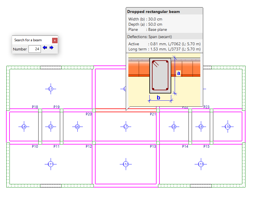
To do this, after clicking on the option, select the beam or wall using the left mouse button, or enter its "Number" in the "Search for a beam" box and press "Enter". When you do this, it will be highlighted in red, and all other beams that are identical to the selected beam will be highlighted in magenta.
Clicking the right-click button will display information about the beam following the current one. You can also use the controls in the "Find a beam" dialogue box to view the "Previous beam" or the "Next beam".
In addition to information on the element’s dimensions, if the structure has been analysed, you will also be able to view information on instantaneous, total and active deflections. If any deflection limit is exceeded, the value will be displayed in red.
View beam layouts
The "View beam alignments" option allows you to check the number of the alignment or frame to which the selected beam belongs.
To do this, after selecting the option, left-click on a beam. The program will display information about the frame to which it belongs in the message bar at the bottom of the main interface.
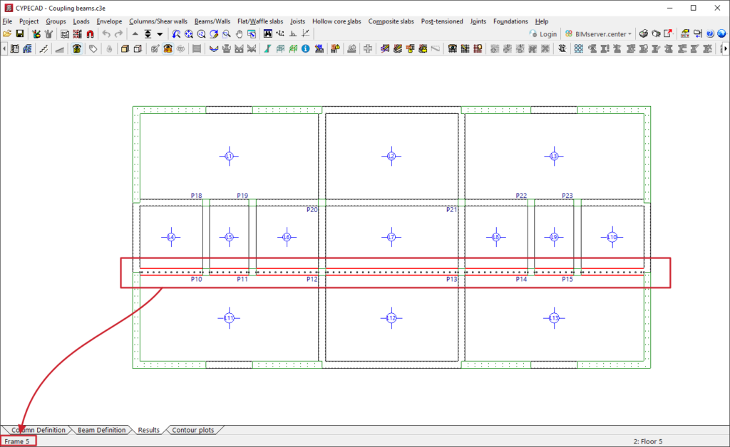
Table of contents
Complete your tour of CYPECAD by exploring the other available sections:
- Introduction
- Introduction and creating new jobs
- General data configuration
- Defining floors and groups of floors and inserting columns, shear walls and starts ("Column input" tab)
- Inserting beams, walls, floor slabs, foundation elements and special elements, and structural analysis (the "Beam Input" tab):
- Checking analysis results and editing elements (the "Results" tab):
- Options on the "Contour plots" tab
- Printing documents and exporting data
- More information:
- General features of CYPECAD