
Setting up views of slab reinforcement and waffle slabs
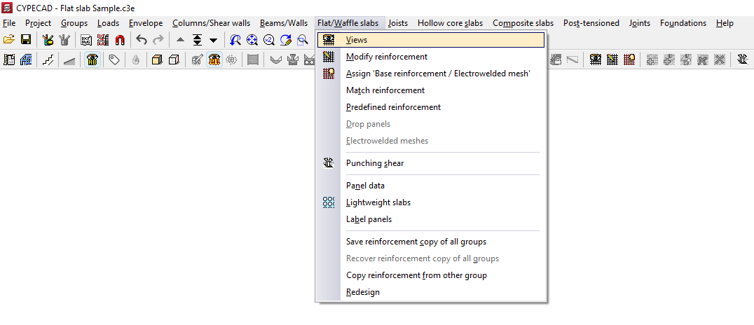
The "Views" option, available in the "Flat/Waffle slabs" menu on the "Results" tab, allows you to select the type of slab and waffle slab reinforcement you wish to view and then configure how it is displayed.
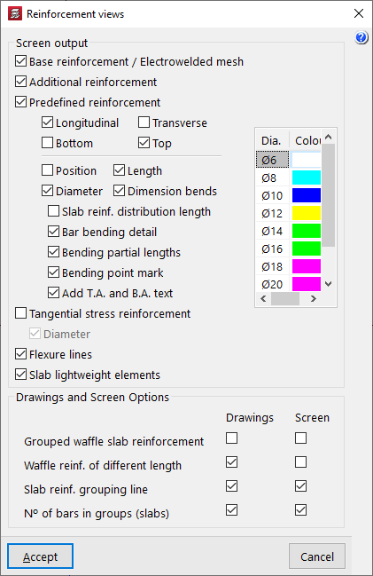
After clicking on this option, the "Reinforcement views" window opens. The "Screen output" section contains the following options for displaying results on screen:
- Base reinforcement / Electrowelded mesh (optional)
Enables the display of the base reinforcement (added using the "Assign 'Base reinforcement / Electrowelded mesh'" option in the "Flat/Waffle slabs" menu). The base reinforcement is displayed with the label 'A.B.'. - Additional reinforcement (optional)
Enables the display of reinforcement. If base reinforcement has been entered for the panels and the options available under "Detail base reinforcement in drawings" (within "Project", "General data", "By position", "Flat, waffle and joist floor slab options"), the base reinforcement is not treated as such, but is considered as the first layer of the reinforcement, so the "Reinforcement" option must be enabled to display it on screen. - Predefined reinforcement (optional)
Enables the display of default reinforcement (inserted using the "Default reinforcement" option in the "Slabs/Grids" menu). - Longitudinal / Transverse / Top / Bottom (optional)
These options allow you to display the longitudinal and/or transverse reinforcement on the top and/or bottom faces of slabs or grid slabs, both in the base reinforcement (or welded mesh) and in the reinforcement or default reinforcement, depending on the boxes that have been ticked. - Position (optional)
Selecting this option displays all the dimensions required for setting out the reinforcement. These dimensions are shown in grey. - Length (optional)
Selecting this option adds the length of the bars to the reinforcement label. - Diameter (optional)
Selecting this option adds the diameter of the bars to the reinforcement label. - Dimension bends (optional)
Enabling this option displays a label showing the length of the bar's bends next to the bars themselves. - Slab reinf. distribution length (optional)
Displays a text field showing the width of the area over which each slab assembly is laid out. - Bar bending detail (optional)
For inclined panels, a bending diagram is drawn next to the bar. - Partial bending lengths (optional)
For inclined sections, the length of the bar on either side of the bending point is specified. - Bending point mark (optional)
On sloping surfaces, the bending point is marked with a line perpendicular to the axis of the bar. - Add T.A. and B.A. text (optional)
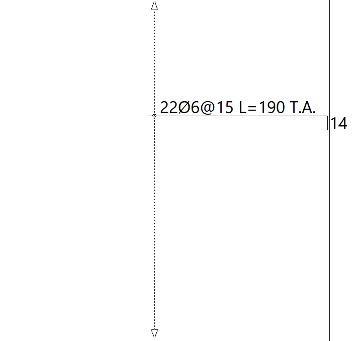
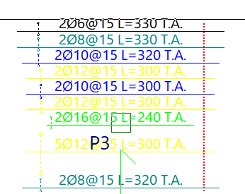
Selecting this option adds the 'T.A.' or 'B.A.' abbreviations to the reinforcement labels, depending on whether it is an upper or lower reinforcement. - Tangential stress reinforcement (optional)
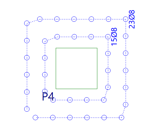
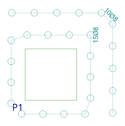
Activates the representation of the tangential stress reinforcement. The tangential stress reinforcement is represented by circles indicating the number of vertical bars to be placed and the spacing between them. Furthermore, if the maximum force is exceeded in a section, a red line will appear along with the label "Insufficient".- Diameter (optional)
Selecting this option displays labels showing the diameter of the reinforcement bars subjected to shear stresses.
- Diameter (optional)
- Flexure lines (optional)
Enables the display of defined bend lines. - Slab lightweight elements (optional)
Enables the display of the lightweighting elements for the slabs (added using the "Lightweight slabs" option).
In addition, on the right-hand side of the table, you can configure the colours of the reinforcement bars. Each diameter of the reinforcement bars is assigned a different colour to make them easier to read on screen. You can change this colour by double-clicking on it and then selecting a different colour from the colour palette that appears.
At the bottom of the dialogue box, under the "Drawings and Screen Options" section, there are various options for configuring the display of reinforcement in both the "Drawings" and on screen ("Screen"):
- Grouped waffle slab reinforcement (optional)
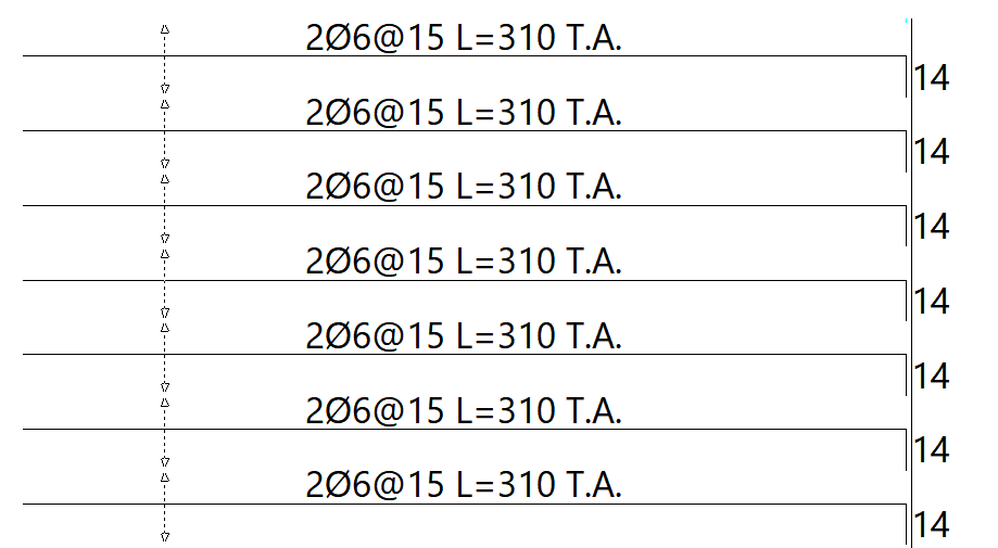
Selecting this option makes all the reinforcement in waffle slabs visible, even if they are grouped. We recommend that you do not enable this option on screen, as it slows down the redrawing of the reinforcement. - Waffle slab reinforcement of different lengths (optional)
Enabling this option displays grouped waffle slab reinforcement bars of different lengths as if they were not grouped. In other words, all reinforcement bars within the group are visible. This option has no effect if the "Grouped waffle slab reinforcement" option is enabled. As with the previous option, we recommend not enabling this on-screen, as it slows down the redrawing of the reinforcement. - Slab reinf. grouping line (optional)
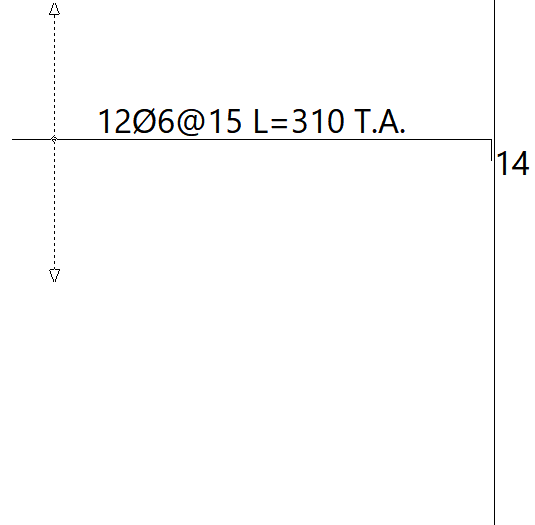
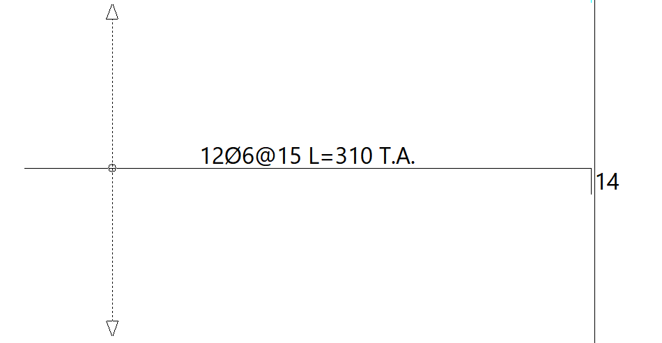
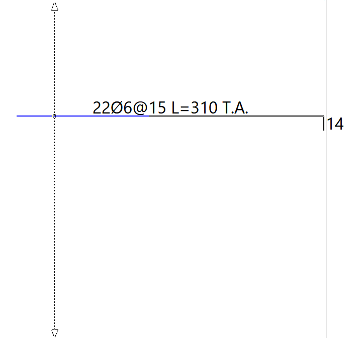
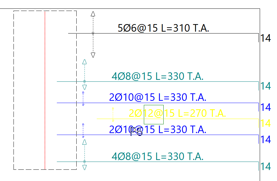
Enabling this option displays slab reinforcement groupings with a line featuring an arrow at each end. If the option is not enabled, only the arrows at the ends of the line will be drawn. - Nº of bars in groups (slabs)
Enabling this option adds the number of bars per reinforcement group to the reinforcement label.
| Note: |
|---|
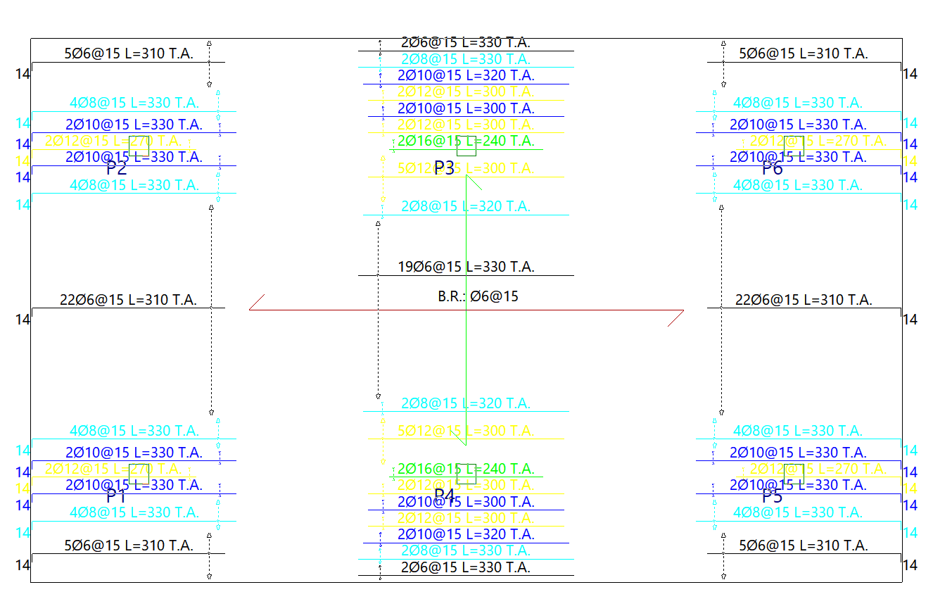
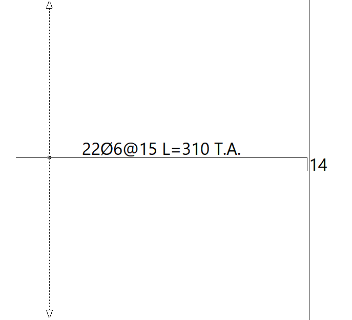
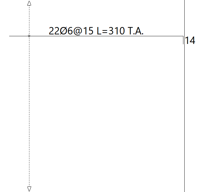
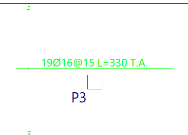
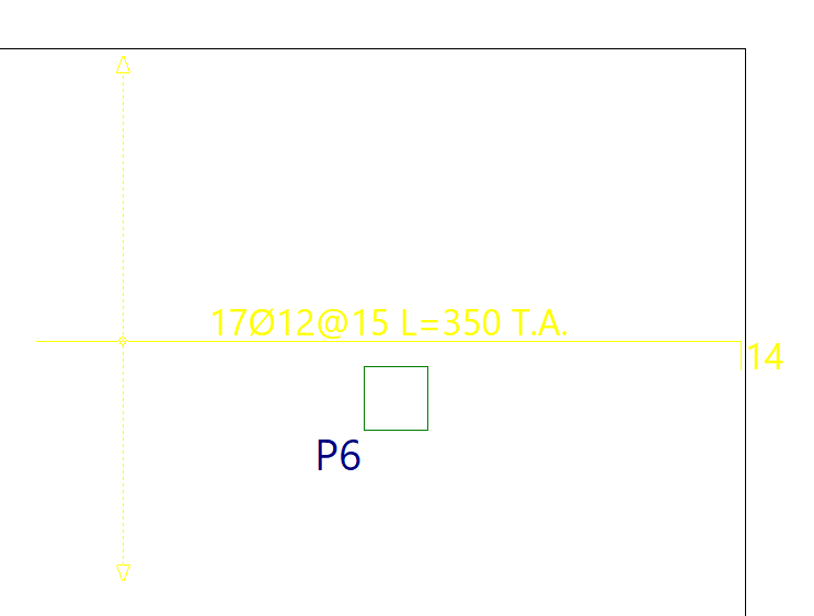
| Thus, the meaning of a label such as '10Ø8@15 L=300 R.S' on a reinforcement cage is as follows: 10 bars with a diameter of 8 mm, spaced 15 centimetres apart and 300 centimetres long, forming part of the top reinforcement. |
Modifying reinforcement for slabs and waffle slabs
The "Modify reinforcement" option, available in the "Slabs/Waffle slabs" menu on the "Results" tab, allows you to make changes to the reinforcement obtained from the analysis of slabs and waffle slabs.
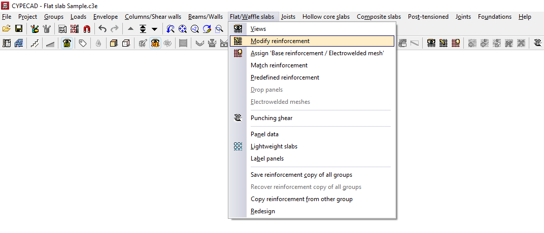
After clicking on this option, the "Modify reinforcement" window opens. Here, first select the type of reinforcement you wish to modify, either "Longitudinal" or "Transverse", and then "Top" or "Bottom".
The "Keep reinforcement views" option allows you to display the reinforcement sets activated via "Slabs/Waffle slabs > Views", which will appear alongside the reinforcement set selected for modification. This allows you, for example, to view the lower longitudinal reinforcement whilst modifying (and therefore also displaying) the upper longitudinal reinforcement.
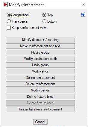
The "Modify reinforcement" window then offers the following options, which will be applied to the reinforcement type selected in that window:
Changing diameters and/or spacing
The "Modify diameters/spacing" option allows you to change the diameters of the bars in a reinforcement bundle and, in the case of slabs, the spacing between bars.
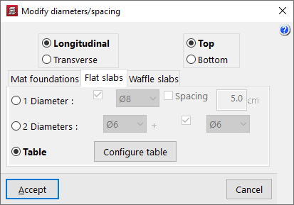
Clicking on this option opens the "Modify diameters/spacing" window.
First, select the reinforcement to be modified: "Longitudinal" or "Transverse", and "Top" or "Bottom". Next, select the appropriate tab based on the type of floor slab being used: "Mat foundation", "Flat slabs", or "Waffle slabs". Once these selections have been made, there are three ways to modify the reinforcement.
- 1 Diameter
The "1 Diameter" option allows you to modify the representative bar for each reinforcement bundle. If you are modifying a slab, the parameters that can be modified are the diameter and/or the "Spacing". If you are modifying a grid, the modifiable parameters are the diameter and/or the number of bars (“No. of bars”). Once the parameters have been selected, click “OK” and then left-click on the bar in the bundle to be modified. - 2 Diameters
The "2 Diameters" option allows you to define two bars in a reinforcement package, so that it consists of pairs of bars in different layers which may have different diameters. If you are modifying a slab, enter the diameters of each of the bars. In grid slabs, you can also define a specific number of bars for the first diameter and another for the second diameter. Once the parameters have been selected, click "OK" and then left-click on the pair of bars in the package to be modified. - Table
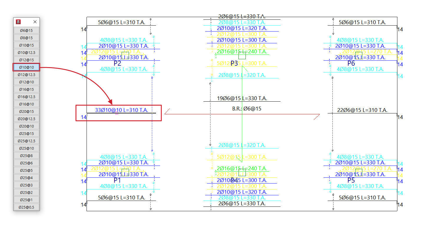
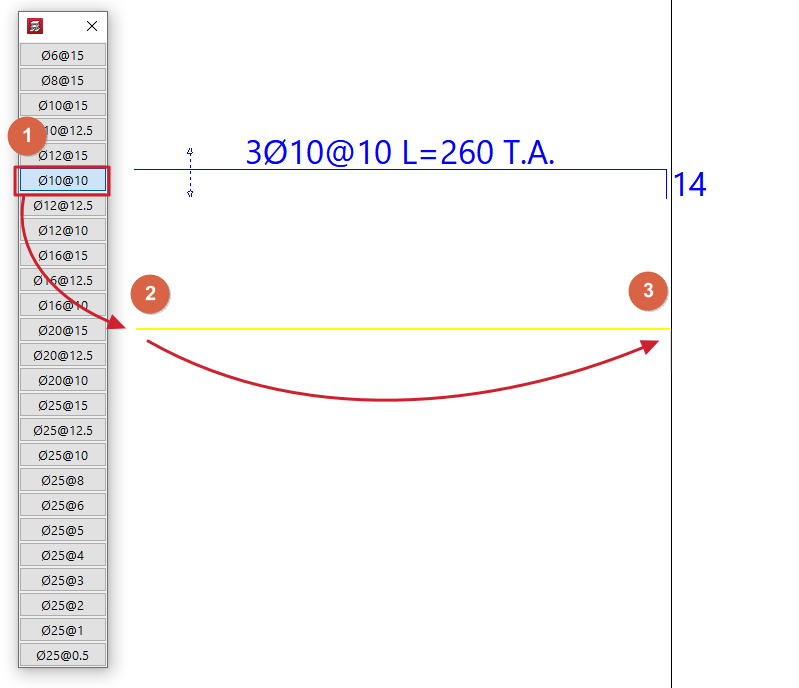
When you select the "Table" option and click "OK", the reinforcement table for the relevant floor slab type will appear on the left-hand side of the screen. The reinforcement is sorted from smallest to largest cross-section. By clicking on one of the reinforcement sets in the table and then clicking on the reinforcement sets or bundles of reinforcement on the floor plan with the left mouse button, the reinforcement set selected in the table is assigned to them. To cancel the operation, click the right mouse button.- The grid that appears can be customised by clicking on the "Configure grid" option. Here you can specify the "Number of rows" and the "Number of columns". By default, a single column and 50 rows are set.
Move layout and text
This "Move reinforcement and text" option allows you to move the reinforcement bar drawings and tags for grouped reinforcements to a different position within the reinforcement package, as specified by the user.
After selecting this option, select the reinforcement to be moved and then the final position where you want to place it.
Modify group
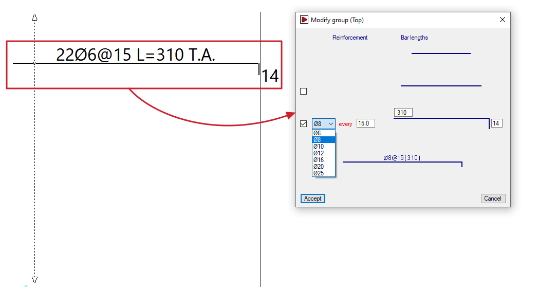
The "Modify group" option allows you to change both the diameter and the length of a group of bars or ribs in grid slabs and slabs simultaneously. In the case of slabs, it also allows you to change the spacing between bars.
When you select an assembly, the "Modify group" window opens, displaying the parameters to be modified, such as the diameter of the package’s bars, their spacing, the bar length, and the tab length. You can tick the relevant boxes to add a second or even a third bar to the package on different layers.
At the bottom of this window, a diagram of the selected assembly is displayed, which changes as the data in the upper section is modified. After clicking "OK", the program updates the assemblies in the package.
Modify distribution width
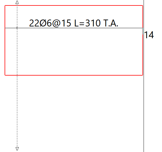
A distribution band is the area in which a specific set of evenly spaced reinforcements is arranged. Using the "Modify distribution width" option, you can extend or reduce a distribution band by selecting one of its edges (the band’s outline is highlighted in red when selected) and moving it to a new position.
When modifying the distribution band of a reinforcement, it may overlap with other reinforcements. If the "Delete overlapped reinforcement" option is enabled, any reinforcements that overlap by at least half their length will be removed, whilst the reinforcements in the modified package will be retained.
Undo group
The "Undo group" option allows you to break down the selected assembly into individual bars, so that they are no longer grouped together.
Modify ends
Using the "Modify ends" option, you can extend or shorten the ends of a selected bar. To do this, click on the end of a bar (the length to be extended or shortened is shown in yellow or blue, respectively) and then click again on the new position for that end.
Define reinforcement
The "Define reinforcement" option is used to add new bars with the diameter and/or spacing selected in the table that appears.
After selecting the diameter and/or spacing from the table, use the cursor to mark the two ends of the bars.
Delete reinforcement
The "Delete reinforcement" option allows you to remove the selected reinforcement package.
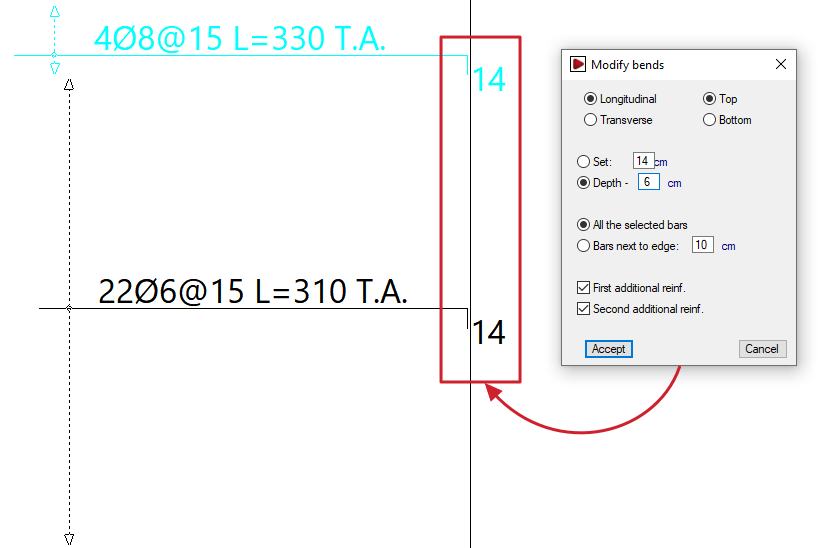
Modify bends
The "Modify bends" option allows you to adjust the lengths of the pins.
Clicking on this option opens the "Modify bends" window. Here, you must first select the position of the reinforcement to be modified: "Longitudinal" or "Transverse", and "Top" or "Bottom".
You can then specify a fixed dimension or define the cantilever based on the edge of the slab:
- Fixed
Allows you to specify the bend length directly. - Overhang - 'X'
You can enter a value of 'X'. The cantilever will have a length equal to the overhang of the slab minus the value 'X' entered.
Further down, you can choose whether to modify all the selected bars or only those near the edges:
- All selected bars
If this option is selected, all bars selected subsequently will have a stirrup attached, even if they do not reach the edge of the slab or openings. - Close to the edge: 'X'
If this option is selected, the specified bracket will be applied to all beams selected subsequently whose ends are less than 'X' centimetres from the edge of the slab.
The following options are also available:
- First reinforcement (optional)
If you enable this option, the specified connection will be applied to all first reinforcement bars (the longest bar if there are several) selected below. - Second reinforcement (optional)
If you enable this option, the specified tab will be added to all the second reinforcement bars (the shortest bar if there are several) that you select below.
After clicking "Accept", select the bars to be modified in the workspace.
| Note: |
|---|
| Bars can be selected by clicking directly on them with the cursor or by using a selection area or window. To do this, click the first point of the window and then a second point: -If you drag from left to right, a solid line window will appear and all bars that are completely within the window will be selected. -If you drag from right to left, a dashed line selection window will appear and the bars within the window will be selected, even if only partially. |
Define flexure lines
The "Define flexure lines" option allows you to enter bending lines using two end points. These can be entered in line with the directions of the supports. The distance between the lines corresponds to the span length.
| Nota: |
|---|
| These lines are treated as if they were points of maximum negative moment. Based on these, and following the minimum percentage distances between lines specified in "Project > General data > By position > Options for slabs, grids and unidirectional elements > Minimum lengths for grids and slabs", the lengths of the negative reinforcement are calculated. Furthermore, the positive reinforcement bars are overlapped on these lines, where possible. It is advisable to make this input before the calculation, as if done afterwards, the overlaps will be construction-related (30 centimetres) and will not be recalculated. |
Delete flexure lines
The "Delete flexure lines" option allows you to remove previously entered fold lines.
Tangential stress reinforcement
The "Tangential stress reinforcement" option allows you to modify the reinforcement for tangential stresses, whether for individual bars or groups of bars.
A group of bars refers to several consecutive bars of the same diameter, shown connected by a dotted line.
Clicking on this option opens the "Tangential stress reinforcement" window, which contains the following options:
- Modify diameter single bar
Allows you to specify a new diameter for a bar. To do this, select the bar on the plan view. If the bar belongs to a group, it will be ungrouped. - Modify diameter group
Allows you to specify a new diameter for a group. To do this, select the group of bars on the floor plan. - Delete single bar
Allows you to delete a single bar or a bar belonging to a group. - Delete group
Allows you to delete an entire group of bars. - Add single bar to a group
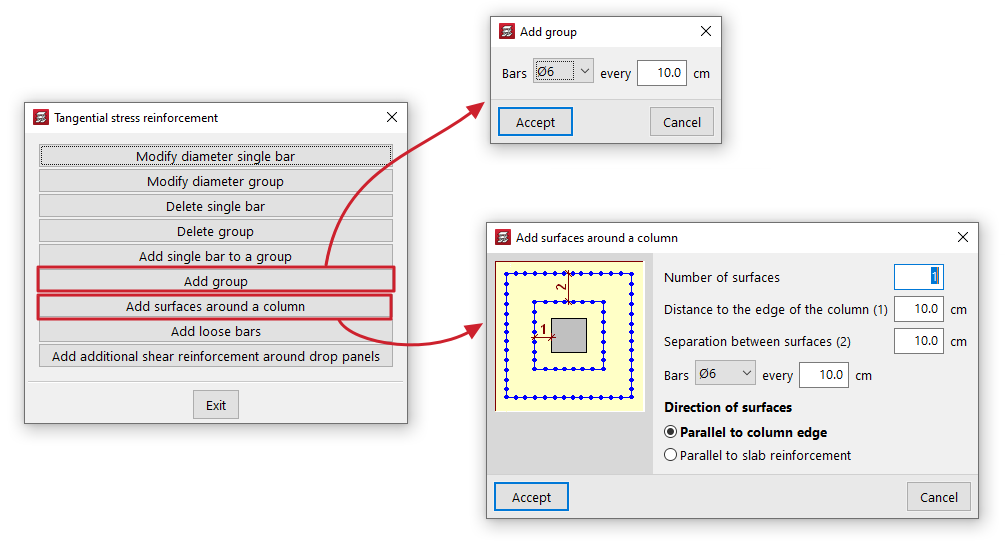
This allows you to insert a single bar into a group of bars. You can only add single bars to groups from which bars have previously been deleted. - Add group
Enter the diameter and spacing of the bars in the group. You must then specify the start and end points of the group on the screen. - Add surfaces around a column
This allows you to generate reinforcement for shear stresses on surfaces around a column. To do this, define the "Number of surfaces", the "Distance to the edge of the column" for the first surface, the "Spacing between surfaces", the diameter of the "Bars" and their spacing. You must also select the "Direction of the surfaces", either "In the direction of the column" or "In the direction of the panel". After clicking "OK", select a column in the plan view. The program will generate the groups of bars around it according to the defined settings. - Add loose bars
Allows you to insert a loose bar. - Add additional shear reinforcement around drop panels
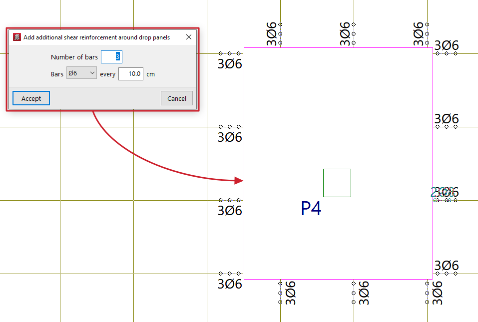
This allows you to add groups of shear reinforcement bars to all ribs connected to a slab without having to select each rib individually. To do this, specify the "Number of bars" to be placed, their diameter and spacing, and select the slab on the floor plan. The new bars will be added even if shear reinforcement bars already exist in the ribs connected to the selected abacus. If you wish to replace the existing bars with different ones, you must first delete the existing reinforcement and then add the new bars.
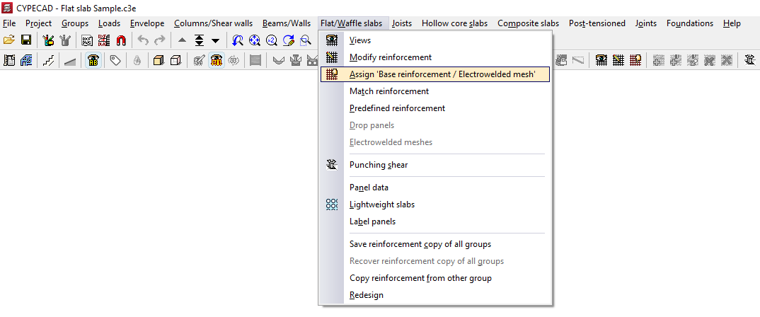
Assigning base reinforcement or electrowelded mesh
The option "Assign 'Base reinforcement / Electrowelded mesh'", available in the "Panels" menu on the "Beam input" tab and also in the "Slabs/Waffle slabs" menu on the "Results" tab, allows you to define base or assembly reinforcement for drop panels, slabs, waffle slabs, in-situ joist floors and composite slabs, as well as welded mesh for slabs.
When you click on the option, if there is more than one type of slab on the current floor, you must select a floor slab using the left mouse button to specify the reinforcement type to be assigned:
- In the case of solid slabs, you will need to choose whether to assign a "Base reinforcement" or an "Electro-welded mesh" by selecting the relevant option in the window that appears.
- In all other cases, the program will allow you to assign a "Base reinforcement".
For analysis purposes, the welded mesh and the base reinforcement are treated in the same way, bearing in mind that, when designing the slab reinforcement, both elements provide a uniform mechanical contribution across the entire span.
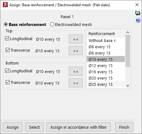
Assignment of base reinforcement
To assign a base framework, you need to configure the following options in the window that appears when you select this option:
- On the left, tick the boxes for the reinforcement types you wish to apply ("Longitudinal" or "Transverse", and either "Top" or "Bottom").
- The "Assemblies" column on the right shows the available base assemblies according to the assembly table that has been configured.
- Using the buttons in the middle (labelled "< <"), you can copy the selected reinforcement on the right to the sections corresponding to the top longitudinal, top transverse, bottom longitudinal and bottom transverse reinforcement on the left. You must click on each of these buttons for every position of the reinforcement, if there are several.
| Note: |
|---|
| If you wish to assign a standard reinforcement configuration that is not available in the table, you must edit the relevant reinforcement table (under "Project > General data > By position") and add that configuration. In the case of drop panels, the minimum reinforcement required for the top-mounted reinforcement is 2∅10 per grid. For this reason, when a lower value, 2∅8, is selected in the reinforcement list, the buttons allowing it to be assigned to the top reinforcement do not appear. Furthermore, for foundation slabs, it is mandatory to place a base reinforcement based on the slab thickness. Consequently, base reinforcement configurations below those defined based on the thickness of the selected foundation slab will not be available. These values can be modified in the program under "Project > General data > By Position > Flat, waffle and joist floor slab options > Minimum quantities". |
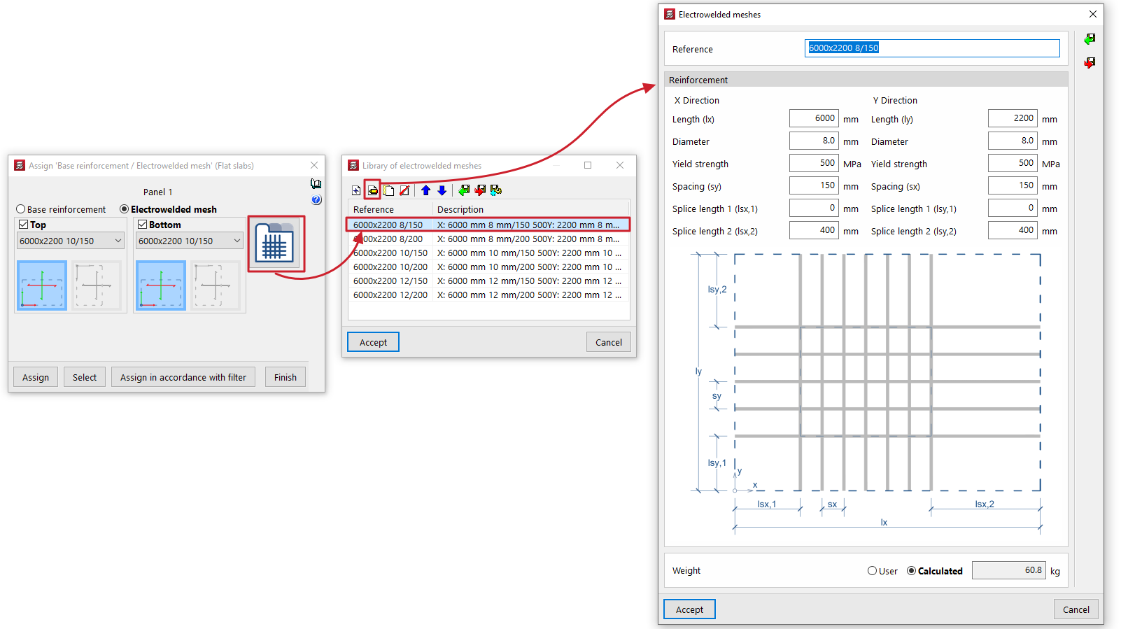
Assigning welded mesh
To assign welded mesh to a solid slab, the window that appears when you select this option allows you to specify the welded mesh to be assigned to both the "Top" and "Bottom" faces of the slab. To do this:
- Select one of the welded mesh options available from the drop-down menu. If you wish to assign a welded mesh that is not listed in the table, you will need to edit the "Welded mesh library" accessible on the right-hand side and, if necessary, modify the welded mesh assembly tables.
- At the bottom, you can specify whether the X and Y axes of the mesh are "Coincident axes" with the slab’s reinforcement axes, or "Transposed axes" (rotated by 90° relative to the slab’s reinforcement axes).
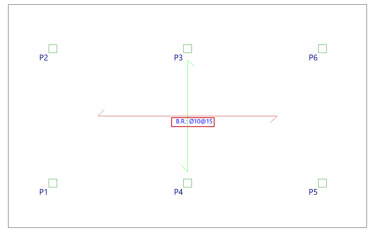
Selecting panels on the floor plan
Once you have defined the base reinforcement or welded mesh to be assigned, click on "Assign" and select the floor panels to which you wish to apply it on the floor plan. If you select a panel of a different type, you will be prompted again to select the base reinforcement to be assigned to panels of that type.
The "Select" option allows you to extract information about the base reinforcement or welded mesh from a panel where it has already been applied.
Furthermore, the "Assign according to filter" option allows you to assign the specified base reinforcement or welded mesh to the panels selected according to the defined filter. The filter can be applied to the "Current group", to "All groups" or to a "Selection of groups". In the list that appears when using this option, you must tick the "Assign" box for the slab types to which you wish to apply the base reinforcement or welded mesh.
Once the base reinforcement or welded mesh has been applied to the panels, you can re-reinforce the slabs via the "Reinforce slabs" option, which is available under the "Match reinforcement" option in the same menu.
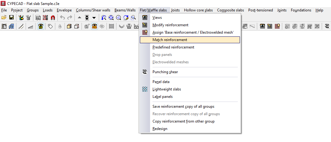
Matching reinforcement for slabs and waffle slabs
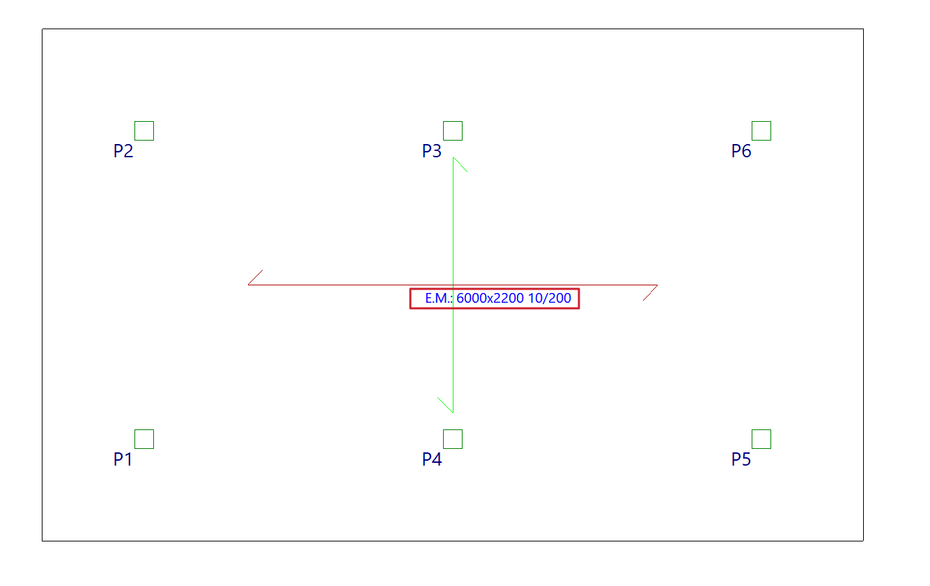
The "Match Reinforcement" option, available in the "Panels" menu on the "Beam input" tab and also in the "Slabs/Waffle slabs" menu on the "Results" tab, allows you to enter alignment lines or rectangles that unify the reinforcement of slabs and waffle slabs obtained after the analysis.
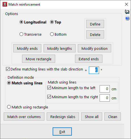
In the "Match reinforcement" window that appears when you click this option, the program offers various operations for aligning the reinforcement in grid slabs or flat slabs:
- Options
- Longitudinal / Transverse / Top / Bottom
This allows you to specify the type of reinforcement you wish to match, whether longitudinal or transverse, on the top or bottom face of the slab. - Modify ends
Moves one end of an alignment line or rectangle whilst keeping the other end fixed. If the "Define matching lines with the slab direction" checkbox is deselected, you can rotate the alignment line by dragging the selected end. - Modify lengths
Changes the minimum lengths of the alignment lines or rectangles entered. If the minimum length options are enabled and defined, they are replaced by the new lengths. If they are not, you must set the desired length by dragging the lines parallel to the main line with the cursor. - Modify position
Changes the position of the alignment line within a rectangle. - Move rectangle
Changes the position of an alignment rectangle. To do this, left-click to select it and drag it to its new position. - Extend ends
Lengthens or shortens the position of the ends of alignment lines and rectangles.
- Longitudinal / Transverse / Top / Bottom
- Enter
After selecting the type of assembly to align and the alignment mode, this allows you to insert alignment lines or rectangles on the floor plan. - Delete
Allows you to delete previously entered alignment lines or rectangles. To do this, go to "Options" and select the assembly in which you entered those lines or rectangles, then select the alignment lines or rectangles on the floor plan using the left mouse button. - Enter levelling lines with slab direction + 'X'º
If you wish to enter a levelling line at any angle, deselect this box. If you wish to set a specific angle, tick this box and specify the angle to be applied. If this box remains ticked with a value of 0°, as is the default, alignment lines can only be entered in the main directions of the slab. - Input mode
Allows you to select whether alignment is performed by lines or by rectangles:- Match using lines
This allows you to enter an alignment line. The procedure is as follows: after selecting the type of reinforcement to be aligned in the "Options" section of this window, click the "Enter" button. Next, enter the alignment line in plan view by marking its start and end points, ensuring it is perpendicular to the reinforcement ribs or bars to be aligned, and extending from the first to the last rib or bar to be aligned. All bars intersected by this line will be aligned when the "Reinforce slabs" option is used.- Min. length on the left / Min. length on the right
If you wish to align the line by adding minimum lengths on both sides of the alignment line, tick these boxes and enter the lengths in centimetres. If you prefer to mark these lengths on the plan, deselect these checkboxes and press "Enter"; then mark the two end points of the line, followed by two points on the plan to define the left and right lengths. This is a way of creating an alignment rectangle.
- Min. length on the left / Min. length on the right
- Rectangular bracing
Allows you to enter a bracing rectangle. The procedure is as follows: after selecting the type of bracing to be entered in the "Options" section of this window, click the "Enter" button. Next, select two opposite corners of the rectangle. This rectangle is equivalent to a line-based equalisation with minimum bar lengths applied on both sides of the line. All bars captured by the rectangle will be equalised when the "Redesign slabs" option is used.
- Match using lines
- Match over columns
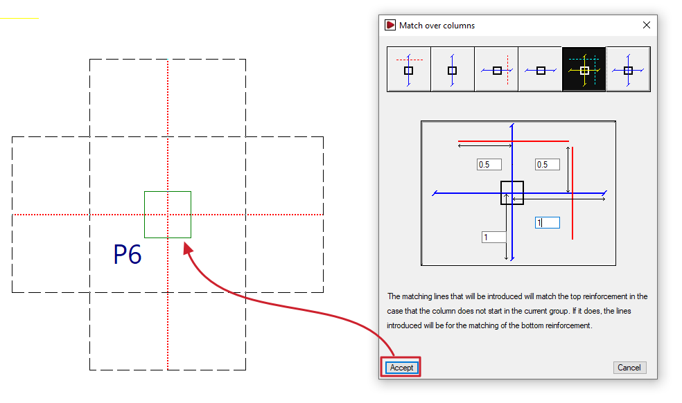
Generates alignment lines or rectangles by entering dimensions from the column centreline to align the negative reinforcement on columns, either transversely, longitudinally or both. The alignment line is shown in blue in the icons in this window, and the length on either side of the line is shown in red. This allows the reinforcement of abaci to be standardised. If the column originates from the current group (for example, if the column is supported on a floor slab or sits on a foundation slab), instead of entering alignment lines for the upper reinforcement, the lines entered will align the lower reinforcement. - Redesign slabs
If the job has been analysed, this option reinforces the slab, taking into account the presence of reinforcement levelling bars and rectangles. - View all
Displays all the alignment lines and rectangles entered on the floor plan, regardless of the assembly type selected in the "Options" section of this window. - Clear
Removes the balancing lines or rectangles that are not in contact with two-way slabs. To delete them, you must select the reinforcement type in "Options" where the balancing lines or rectangles were entered.
Reinforcement matching consists of determining an envelope of reinforcement, which is roughly equivalent to selecting the largest cross-sectional area and length of reinforcement from all the ribs or reinforcement bars intersected by each matching line.
Matching lines or rectangles will be drawn in red if they are for upper beams and in blue if they are for lower beams, and they remain in place even if the structure is redesigned.
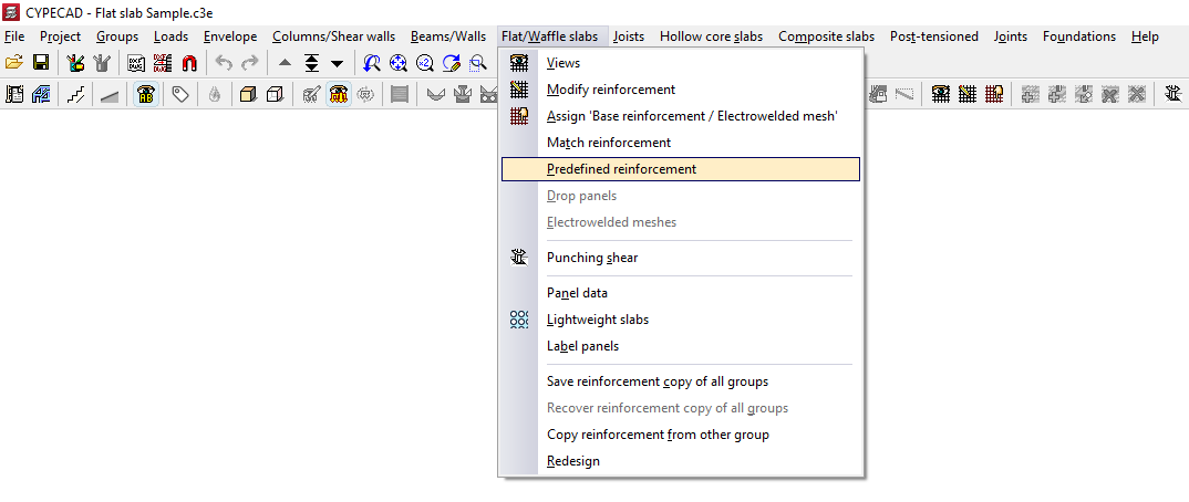
Inserting default reinforcement in slabs and waffle slabs
The "Predefined reinforcement" option, available in the "Panels" menu on the "Beam input" tab and also in the "Slabs/Waffle slabs" menu on the "Results" tab, allows the user to freely enter reinforcement in slabs and grid structures in any direction.
The predefined reinforcement, like the base reinforcement, is retained in subsequent redesigns, and its quantity is deducted from the required amount when analysing the reinforcement layout.
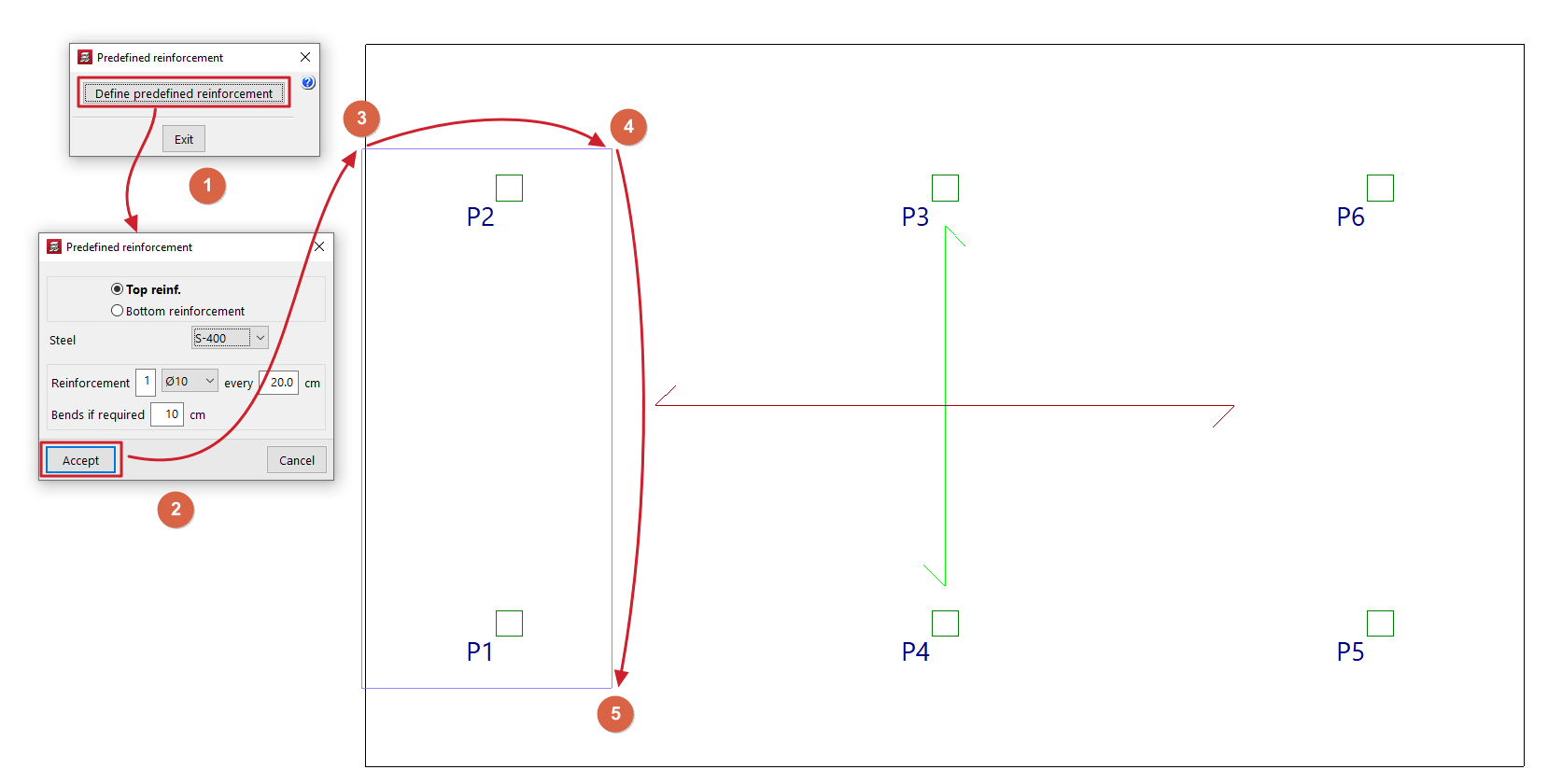
After clicking on this option, the "Predefined reinforcement" window opens, which contains the following options.
Enter predefined reinforcement
Use "Enter default reinforcement" to enter reinforcement for grid slabs and slabs in any direction.
After clicking on the option, in the window that appears, you must specify the position of the default reinforcement, whether it is an "Top reinforcement" or a "Bottom reinforcement", and select one of the available "Steels" (you can specify a different steel grade to the one selected for the main reinforcement of the panel). Define the "Reinforcement" by specifying the number of bars, their diameter and spacing, and indicate the length of the "Anchors if required".
After clicking "Accept", the start and end points of the first beam are marked on the floor plan, and then a third point is selected to indicate the width of the distribution zone for the reinforced concrete package.
Delete default formatting (Upper/Lower)
The options "Delete default reinforcement (Top)" and/or "Delete default reinforcement (Bottom)" appear if default reinforcement has previously been entered on the top and/or bottom face of the slab, and allow it to be removed.
Regenerate bars
If default reinforcement has been entered and a change to the floor plan requires this reinforcement to be modified, using the "Regenerate bars" option will cause the program to redraw the bars, performing operations such as extending them or anchoring them at the ends, where possible.
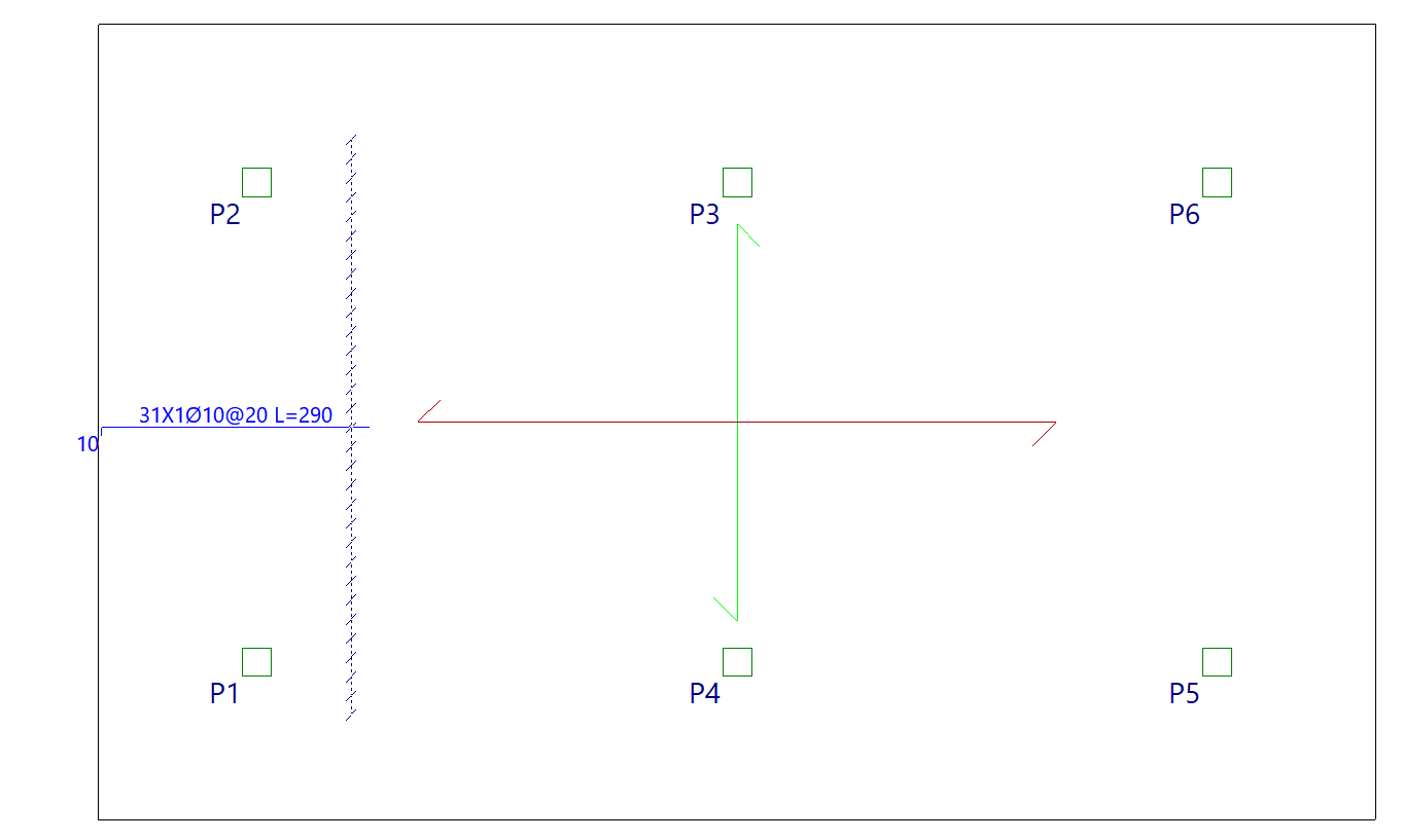
| Note: |
|---|
| The program will deduct the default reinforcement from the analysed reinforcement, such that the average mechanical capacity of the default reinforcement entered (multiplied by the centre-to-centre distance in the case of a grid slab) will be subtracted from the analysed reinforcement. The average mechanical capacity of the default reinforcement is the result of dividing the total mechanical capacity of the entered default reinforcement by the width of the zone where that reinforcement has been entered. |
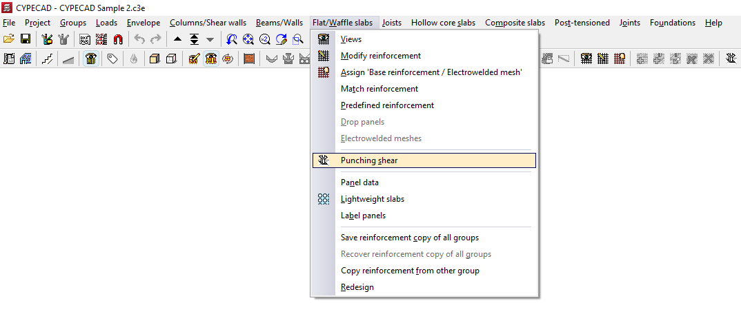
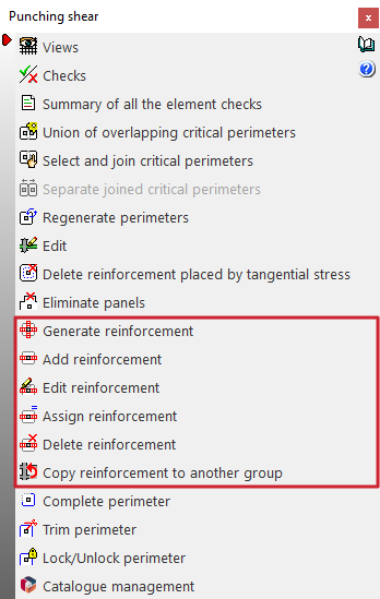
Options for generating and editing punching shear reinforcement
The following options, accessible from the "Punching shear" option in the "Flat/Waffle slabs" menu, in the "Results" tab, can be used to generate and edit punching shear reinforcement for flat slabs and waffle slabs in the program:
- Generate reinforcement
- Add reinforcement
- Edit reinforcement
- Assign reinforcement
- Delete reinforcement
- Copy reinforcement to another group
The insertion of punching shear reinforcement using these options allows you to perform the punching shear check according to regulatory criteria, which can be consulted using the tools available in this same menu.
The reinforcement automatically calculated by the program based on the tangential stresses can serve as a reference for the generation, editing and manual adjustment of the reinforcement bars that are entered using the options in this menu, but it is not considered in the regulatory punching shear verification process and should be deleted afterwards to avoid duplication.
Each of the above features is detailed below:
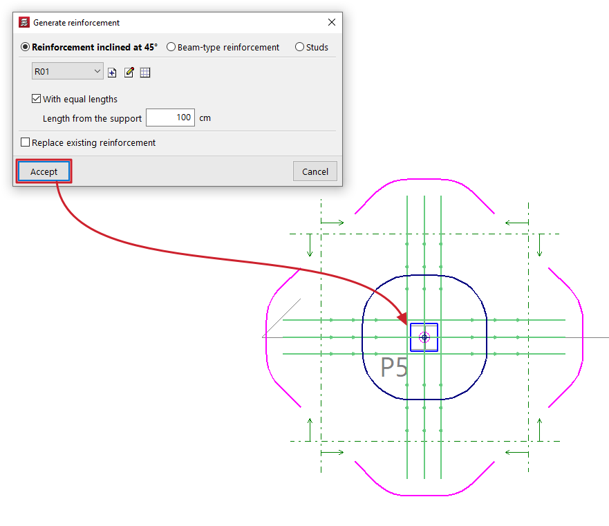
Generate reinforcements
You can define a type of punching shear reinforcement (either "45º inclined reinforcement", "Beam-type reinforcement" or "Bolts") and apply it automatically to each of the supports selected in the plan.
Optionally, you can generate reinforcements "With equal lengths", given a "Length from the support".
If you tick the "Replace existing reinforcements" box, the reinforcements previously entered in the selected supports will be replaced by the reinforcements defined at this time.
If the box remains unchecked and the program detects that the selected support already has punching shear reinforcement, it will warn you that if you continue with the generation, the current reinforcement will be replaced.
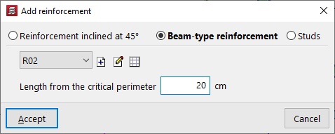
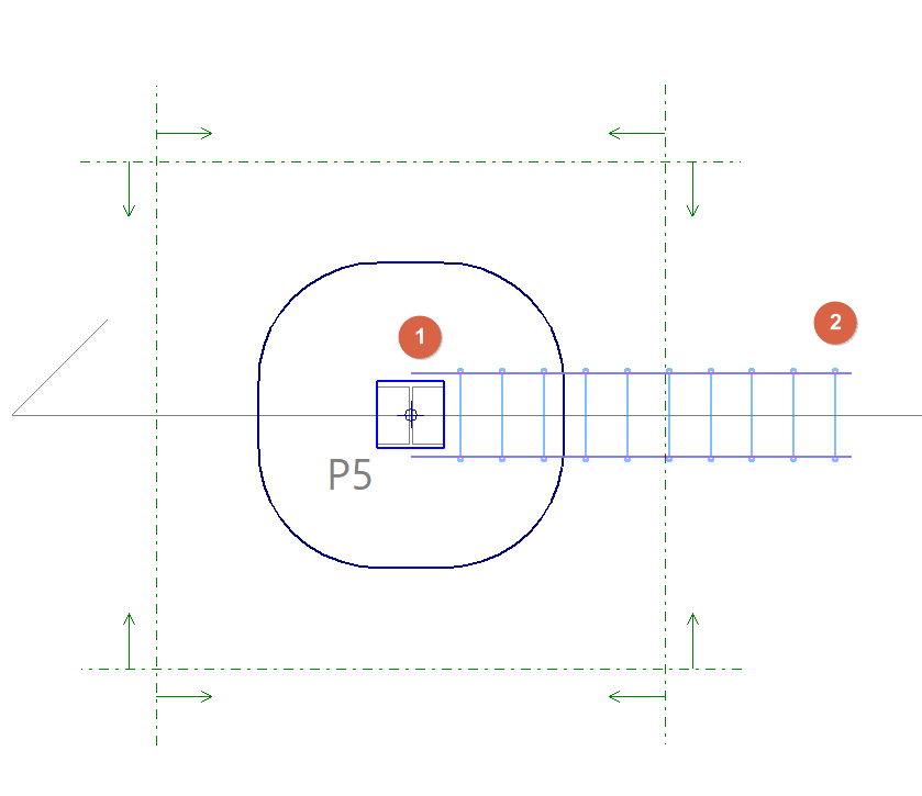
Add reinforcement
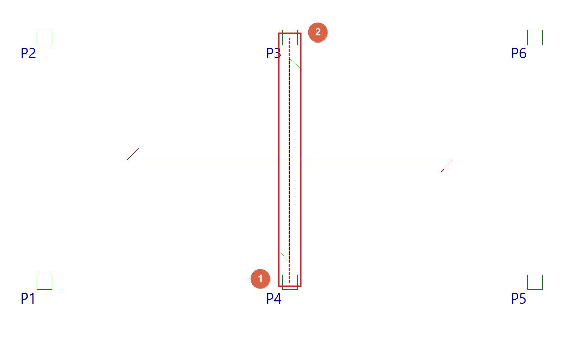
You can define a type of punching reinforcement (either "45º inclined reinforcement", "Beam-type reinforcement" or "Bolts") and enter it manually in the plan.
To do this, mark a support as the starting point (1) and then another point on the slab or floor as the end point (2).
For inclined reinforcement and beam-type reinforcement, the "Length from the critical perimeter" is indicated.
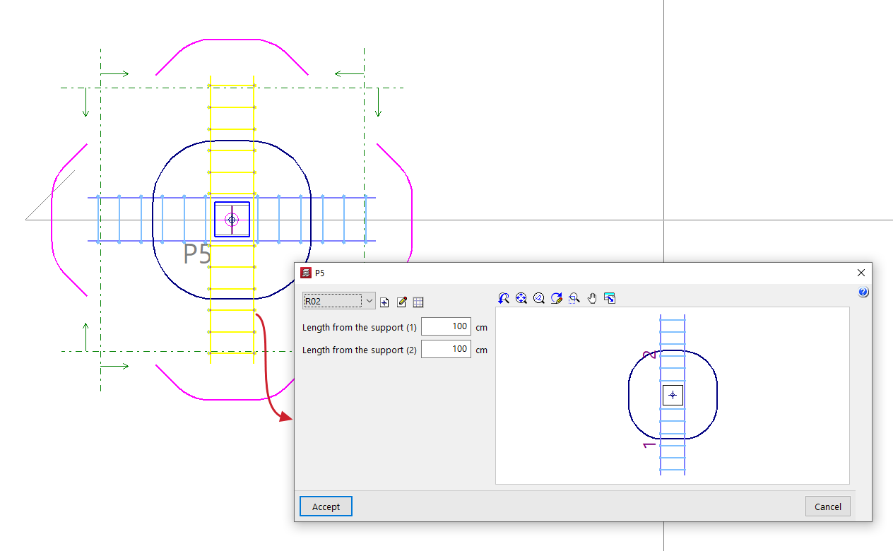
Edit reinforcement
You can edit a punching shear reinforcement previously entered with the ‘Generate reinforcements’ or ‘Add reinforcement’ options, selecting a different type of reinforcement or modifying its characteristics.
If necessary, you can also modify its "Length from the support" by entering its value directly. In "Bolt" type reinforcements, changing the "Number of bolts" will modify the length of the reinforcement.
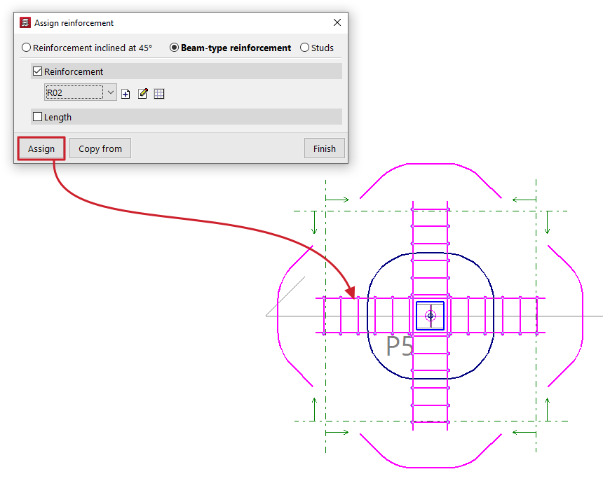
Assign reinforcement
You can define the characteristics of a punching shear reinforcement in the pop-up window and, using the "Assign" option, apply them to reinforcements of the same type previously entered in the plan.
The "Copy from" option allows you to extract information from a selected reinforcement.
By activating the corresponding boxes, it is possible to assign only the "Reinforcement" or the "Number of bars" in "45º inclined reinforcement" type reinforcements; the "Reinforcement" or the "Length" in "Beam type reinforcement"; and the type of "Bolt", its "Layout" or the "Number of bolts" in "Bolt" type reinforcements.
Delete reinforcement
You can delete previously entered punching shear reinforcements by selecting them one by one on the floor plan with the left button or by marking a capture area.
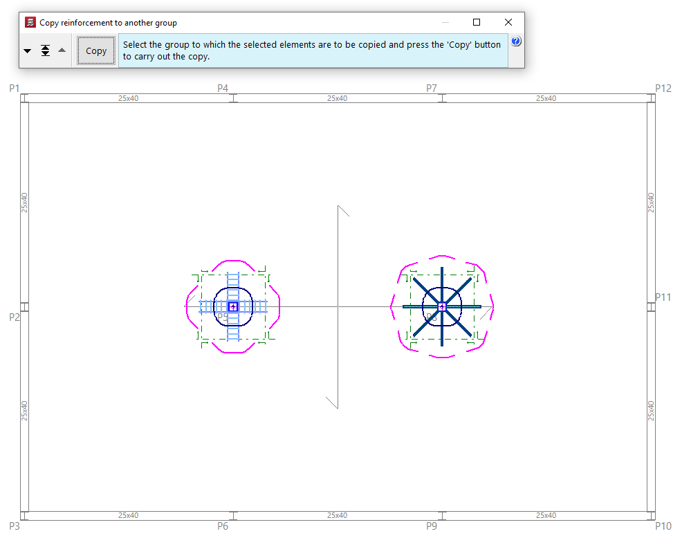
Copy reinforcements to another group
You can select punching reinforcements in plan one by one with the left button or by marking a capture area and, after pressing the right button, select a group where you want to copy the selected elements using the tools available in the pop-up window ("Move group down", "Go to group" and "Move group up").
Press the "Copy" button to make the copy.
Options for copying floor slabs
The following options are available in the "Slabs/Waffle slabs", "Joists", "Hollow core slabs" and "Composite slabs" on the "Results" tab, allowing you to save and retrieve copies of the slab reinforcement for all groups, or to copy slab reinforcement from one group to another.
Selecting these options only affects the type of floor slab in the relevant menu where they have been selected.
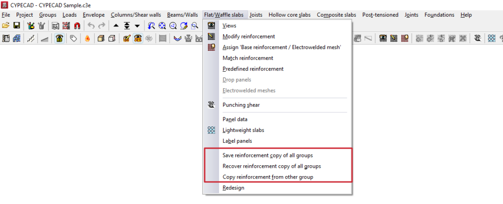
Save reinforcement copy of all groups / Recover reinforcement copy of all groups
These options allow you to save and restore backup copies of the reinforcement layout for the relevant type of floor slab in all groups, should it be necessary to redesign the structure, thereby preventing the loss of work carried out on the reinforcement.
The process is as follows:
- In a previously analysed project, the user makes manual modifications to the reinforcement in the parts of the model that require them.
- The "Save reinforcement copy of all groups" option is used to save the reinforcement with these modifications. Any modifications made to the reinforcement after this copy has been saved will not be saved.
- Subsequently, modifications are made to the projects that require a reanalysis (for example, by adding new elements to the structure).
- The project is reanalysed. During the reanalysis process, the program will have automatically made modifications to the floor structures of all groups, thereby losing the changes made manually.
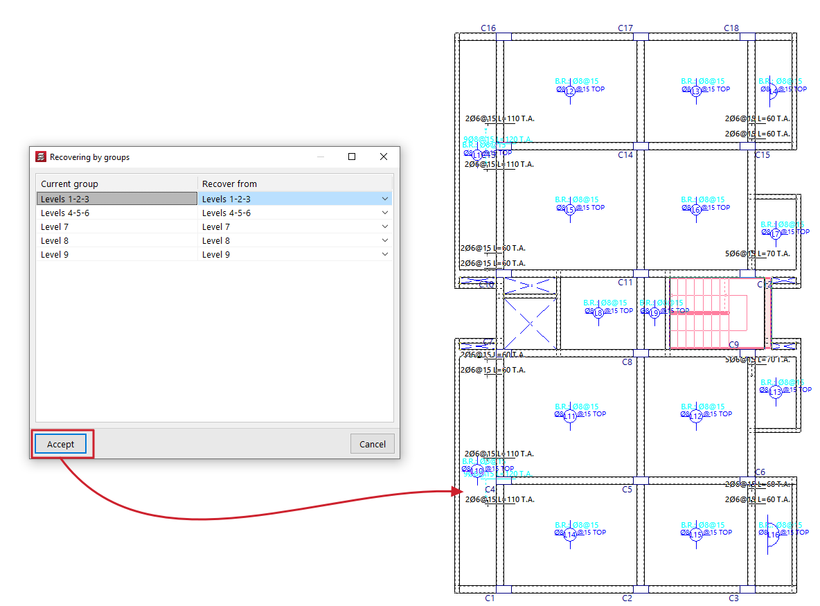
- At this point, use the "Recover reinforcement copy of all groups" option. In the window that appears, you must specify, for each ‘Current group’, the reinforcement you wish to restore (in the ‘Restore from’ column) from those available in the previous save.
Copy reinforcement from another group
This option allows you to copy the layouts from one group of floors to another.
This is particularly useful in cases where there are floors with identical layouts and loads: you would simply need to make the changes to the reinforcement for one of them, and then copy the reinforcement.
To make a copy, follow these steps:
- Firstly, you need to select the target reinforcement (the reinforcement into which you wish to copy the structure of another reinforcement).
- Next, click on the "Copy reinforcement from another group" option in the relevant menu.
- Next, in the window that opens, select the group of floors from which you wish to copy the layout.
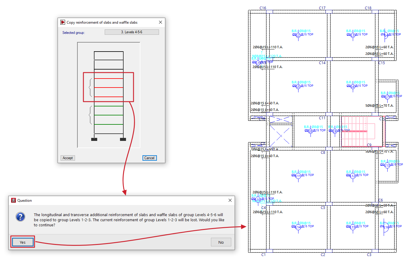
| Note: |
|---|
| If the target floor plan has a different layout from the standard floor plan, the reinforcement will only be copied in areas where there is a floor slab. In openings, the reinforcement is cut off, and no stirrups are placed. Furthermore, both the angle and the intersection point of the mesh must match. For this reason, when defining a group of floors, it is recommended to always copy the immediately preceding group. It is important to check any bars that have been cut, adding the corresponding stirrups or making any other necessary adjustments. |
Table of contents
Complete your tour of CYPECAD by exploring the other available sections:
- Introduction
- Introduction and creating new jobs
- General data configuration
- Defining floors and groups of floors and inserting columns, shear walls and starts ("Column input" tab)
- Inserting beams, walls, floor slabs, foundation elements and special elements, and structural analysis (the "Beam Input" tab):
- Checking analysis results and editing elements (the "Results" tab):
- Options on the "Contour plots" tab
- Printing documents and exporting data
- More information:
- General features of CYPECAD