
Inserting sloping floor slabs and elevation changes in slabs
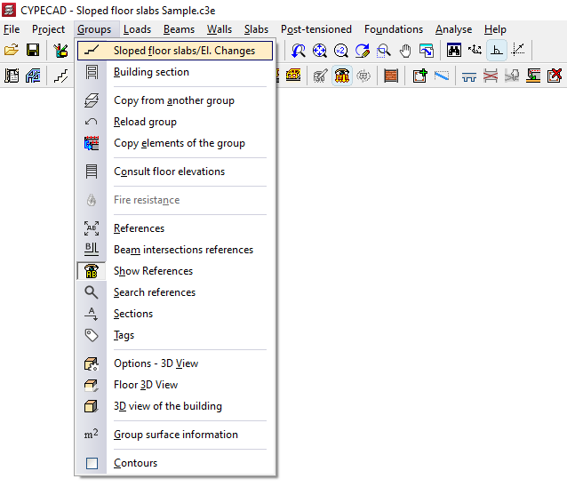
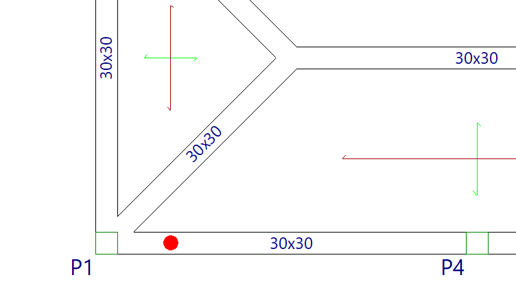
The "Sloped floor slabs/Elevation changes" option, within the "Groups" menu of the "Beam input" tab, allows you to define and assign sloped floor slabs or elevation changes to the floor slabs previously entered on each floor. You can slope or change the level of one, several, or all of the floor slabs on the same floor.
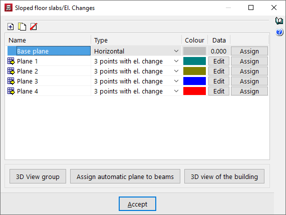
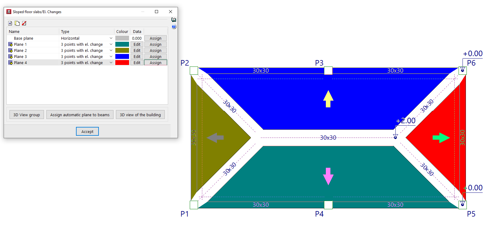
Clicking on this option opens the "Sloped floor slabs/Elevation changes" window. This window displays a list of the different sloped floor slabs or elevation changes with defined uneven surfaces that are available for assignment to specific slab sections in the floor plan.
The following tools appear at the top of the list:
- Add
Add new planes to the list. - Copy
Duplicates the selected plane. - Delete
Removes planes from the list.
In addition, the list displays the following columns:
- Name
Name of the defined plane.- If the plane is assigned to a section of the floor plan, a yellow arrow symbol on a grid is displayed on the left.
- If the plane is defined but has not yet been assigned to any floor, this symbol is not displayed.
- Type
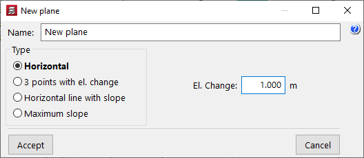
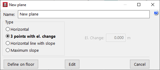
Indicates whether the plane corresponds to a "Horizontal" plane with a slope or whether it is an inclined plane that allows you to define inclined slabs, either by means of "3 points with el. change", following a "Horizontal line with slope" or having indicated the "Maximum slope" straight line. - Colour
Indicates the colour used to draw the cloth assigned to that plane. - Data
Allows you to edit the data needed to define the plan:- In "Horizontal" planes, the distance of the defined plane from the base plane is indicated. This distance can be negative (the plane is below the base plane) or positive (the plane is above the base plane).
- In "3 points with unevenness" type plans, three points are indicated on the plan with the relative elevation of each one with respect to the elevation of the base plan.
- In "Horizontal line with slope" type plans, two points are selected on the floor plan, the relative elevation of both points with respect to the base plane elevation is indicated, and the slope value is specified. The direction of maximum slope will be perpendicular to the line connecting both points.
- In "Maximum slope" type plans, two points are selected on the plan, the relative elevation of the first point with respect to the base plane elevation is indicated, and the slope value is specified. The direction of maximum slope will be indicated by the straight line connecting both points.
- Assign
By clicking this button, you can assign the corresponding plane to the section or sections selected on the floor plan with the left mouse button. The upper face of the selected panel will be flush with the elevation of the plane being assigned. The selected panel or panels will take on the colour that was assigned in the list to the plane that has just been selected.
| Note: |
|---|
| The data in the "Base plane" cannot be changed. It corresponds to a horizontal plan with a level difference of 0 with respect to the current floor and will initially be assigned to all sections of the floor. |
This dialogue box also contains two buttons for viewing the changes made to the allocation of levels to the panels in three dimensions:
- 3D group view
Displays a 3D view of the group being visualised, where you can see the sloping floors or unevenness applied. - 3D view of the building
Shows a 3D view of the entire building, where you can see the entire structure with sloped floor slab or elevation changes in any group.
| Note: |
|---|
| A flat beam located on the border between floor slabs at different levels will take the edge it had before the difference in height was applied, plus the difference in height between the two slabs. For example, a flat beam connected to two slabs with a depth of 27 centimetres, one of which has an assigned height difference of 30 centimetres above the floor level and the other without an assigned height difference, will have a depth of 57 centimetres and will be flush with the upper face of the higher slab and the lower face of the lower slab. |
Table of contents
Complete your tour of CYPECAD by exploring the other available sections:
- Introduction
- Introduction and creating new jobs
- General data configuration
- Defining floors and groups of floors and inserting columns, shear walls and starts ("Column input" tab)
- Inserting beams, walls, floor slabs, foundation elements and special elements, and structural analysis (the "Beam Input" tab):
- Checking analysis results and editing elements (the "Results" tab):
- Options on the "Contour plots" tab
- Printing documents and exporting data
- More information:
- General features of CYPECAD