
Entering reinforced concrete walls, plane stress walls and masonry walls
To insert reinforced concrete walls, flat slab walls or masonry walls in CYPECAD, open the "Beams input" tab, access the “Walls” menu and select the option “Insert wall”.
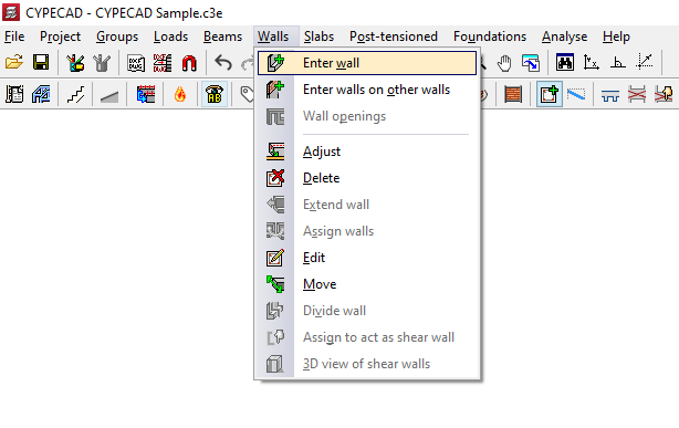
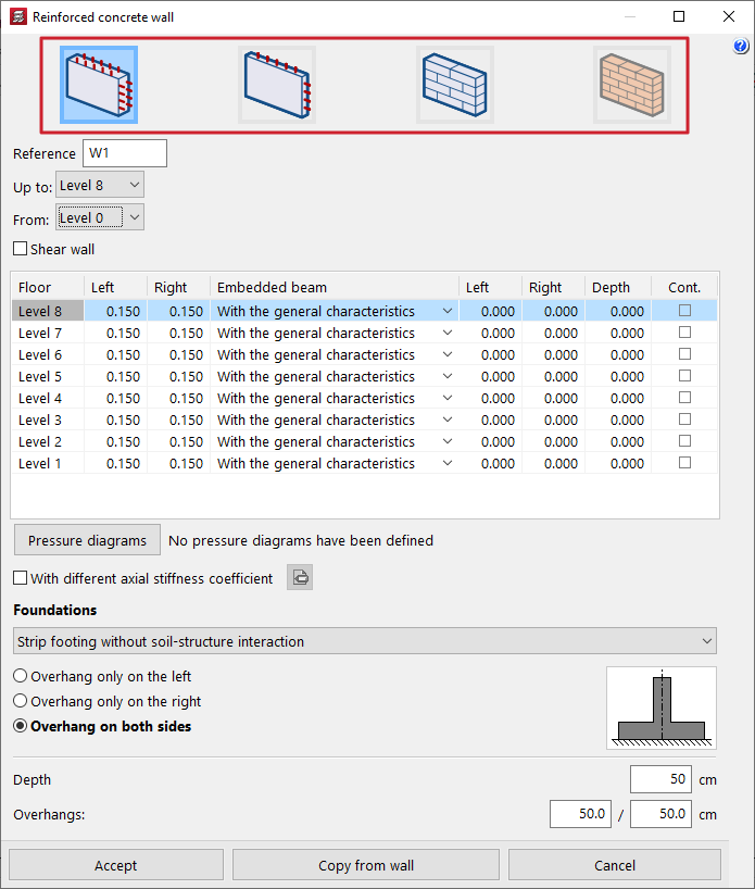
When this option is selected, the program displays the wall characteristics definition window.
This allows the following wall types to be inserted, depending on the selection made at the top:
- reinforced concrete walls, or reinforced concrete walls with two reinforcement planes;
- flat stress walls, or reduced-thickness reinforced concrete walls with a single reinforcement plane;
- concrete block walls;
- and brick masonry or rubble masonry walls.
The definition options for several of the available wall types are similar and are described later.
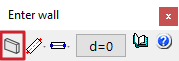
This window can be accessed from the dialogue box that appears when inserting the wall, which contains options allowing the following actions:
- select the current wall, indicating the wall typology to be inserted and the dimensions of its cross section;
- select the wall insertion mode (between "Simple", "Continuous" and "Capture");
- select the wall alignment line to be inserted (between "Left", "Centre" and "Right");
- and define the offset between the insertion line and the wall.
| Note: |
|---|
| These options are analogous to those that appear in the beam insertion process. See this link to understand how they work. |
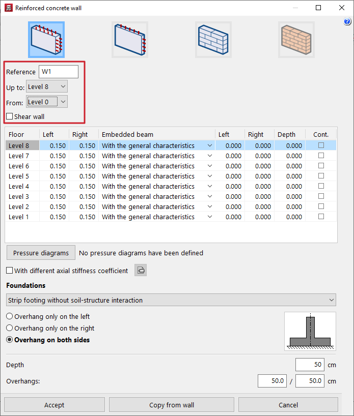
Definition of the wall reference and height
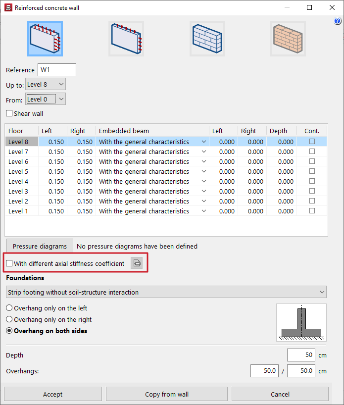
In the wall definition window, the first step is to define the wall "Reference".
The "From" and "To" drop-down lists allow the groups of storeys where the wall starts and ends to be specified.
| Note: |
|---|
| If a particular storey does not appear, it is because it forms part of a group containing more than one storey. The storey must be ungrouped in order to be selectable. |
Shear wall condition
In the case of concrete walls and flat stress walls, it is optionally possible to indicate that the wall is a "Shear wall" by activating the corresponding checkbox and entering a "Label" for the wall. All walls with the same label are grouped to form a shear wall.
| Note: |
|---|
| These walls take part in the analysis of forces but are not designed in CYPECAD. To calculate their reinforcement, an export to BIMserver.center must be performed, and the information must then be imported into a program capable of doing so, such as StruBIM Shear Walls. |
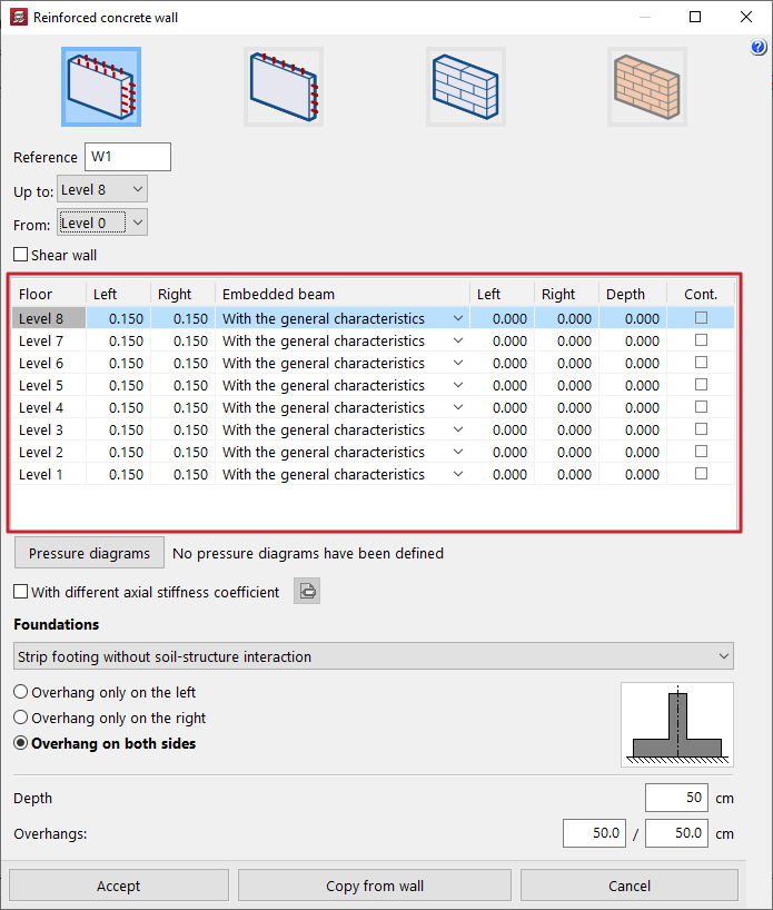
Definition of wall thicknesses and embedded beams
The program then displays a table that allows the following information to be entered, related to wall thicknesses and to the geometry of any beams embedded in the wall:
- In the first columns, the thicknesses to the "Left" and "Right" of the wall are defined on each storey it passes through, measured from the insertion axis.
- In the "Embedded beam" column, the geometry of the embedded beam or capping beam present on each storey crossed by the wall is defined. This can be done by selecting:
- "With general characteristics";
- "With particular characteristics", in which case the beam thickness to the "Left" of the wall, to the "Right", and its "Depth" are entered;
- or not defining it at all ("No embedded beam").
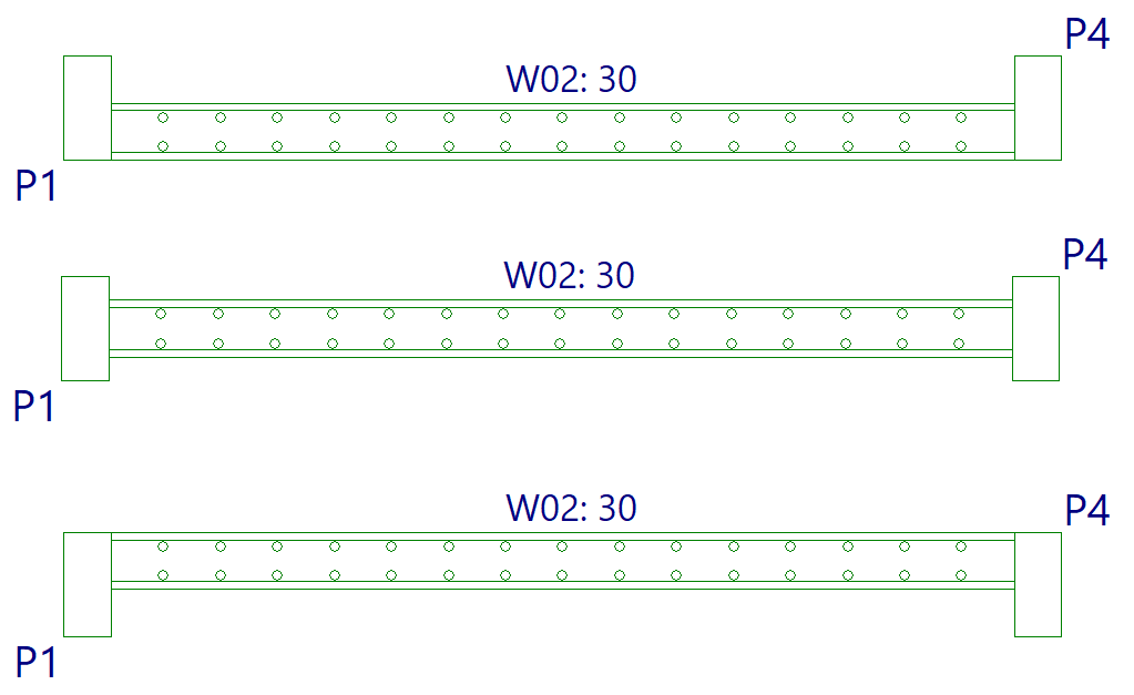
- Finally, the right-hand checkbox in the "Cont." column allows the reinforcement to be indicated as continuous: when selected, the current storey and the one above form a single reinforcement segment.
The left or right dimension is established with respect to the wall insertion direction: when looking from the starting point of the wall towards the end point, the left side is the one on the left of the line joining them, and the right side is the opposite.
| Note: |
|---|
| In general, it is recommended to use the same thickness on the left and on the right, corresponding to half of the total wall thickness. It is also possible for a wall to have different thicknesses on each storey while remaining aligned to one face. To do this, the same thickness value is maintained on the left or on the right on all storeys, and the other thickness is modified on each storey. |
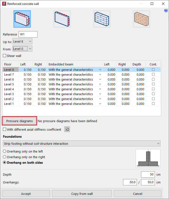
Pressure laws acting on the wall
The "Pressure laws" option allows earth pressures or generic pressure laws to be applied to the left face and/or the right face of the wall, by selecting them from a previously defined "List of pressure laws".
| Note: |
|---|
| This option is not available for flat stress walls, as this structural solution is not designed to withstand out-of-plane bending forces. |
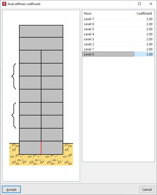
Axial stiffness coefficient of the wall
By activating the "With different axial stiffness coefficient" checkbox, the value of this coefficient can be edited on each storey of the wall.
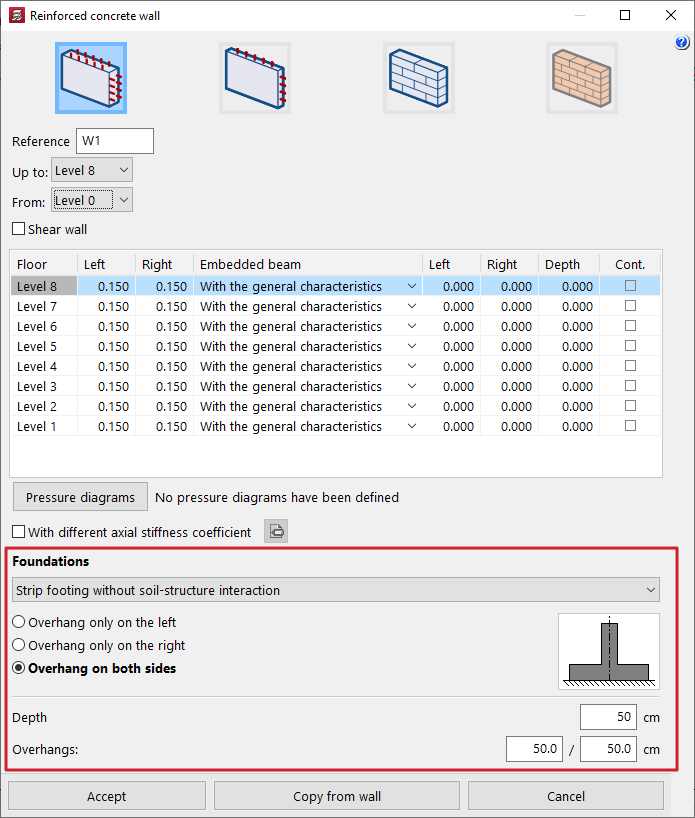
Definition of the wall foundation or support
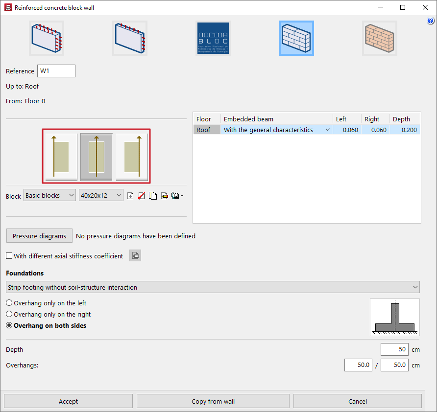
In the "Foundation" section, the wall support conditions are defined by choosing one of the available options from the drop-down list.
- Fixed support
If this option is chosen, the program does not define any type of foundation. Foundation elements for the wall can later be inserted using the specific options in the "Foundation" menu, as with columns and core walls. This can also be useful in cases where a common foundation element is required for several walls.
- Strip footing without soil-structure interaction
The wall is defined on a strip footing without soil-structure interaction. In this case, it is selected whether the footing will have "Overhang to the left only", "Overhang to the right only" or "Overhang on both sides". The "Depth" and the footing "Overhangs" to the left and/or right are then specified.
- Strip footing with soil-structure interaction
The wall is defined on a strip footing with soil-structure interaction. In this case, in addition to the data indicated in the previous option, the value of the "Subgrade modulus" must be defined, allowing footing settlement to be considered.
- Foundation beam
The wall is supported on a foundation beam. In this case, the "Left overhang", "Right overhang" and "Depth" of the foundation beam are defined. In the lower part, the "Allowable soil stresses" are defined for both "Persistent situations" and "Seismic and accidental situations", as well as the "Subgrade modulus". It is possible to "Import usual project values" for the allowable stresses using the assistant on the right.
- Propping
This option is used for walls propped on beams and allows the geometric definition of the support beam beneath the wall directly by entering the "Left overhang", the "Right overhang" and the "Depth". This automatically generates a beam beneath the wall with these characteristics, without the need to insert a separate beam using the specific options.
All the values described can be collected by clicking on "Copy from wall" and then selecting another wall in the project with all the information already defined.
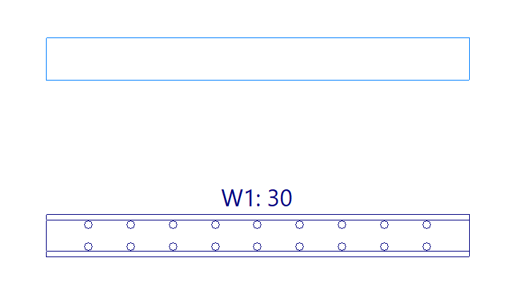
Wall layout in plan
After completing the wall definition, click accept. At this point, the pointer can be moved over other inserted elements such as columns, beams and other walls to capture them, or the "Template snaps" on the upper toolbar can be activated and used.
Click to define the starting point of the wall, and then click a second time to define the end point of the wall.
By doing this, the wall is inserted simultaneously together with the defined foundation or support element, as well as the embedded or capping beams specified in its definition panel.
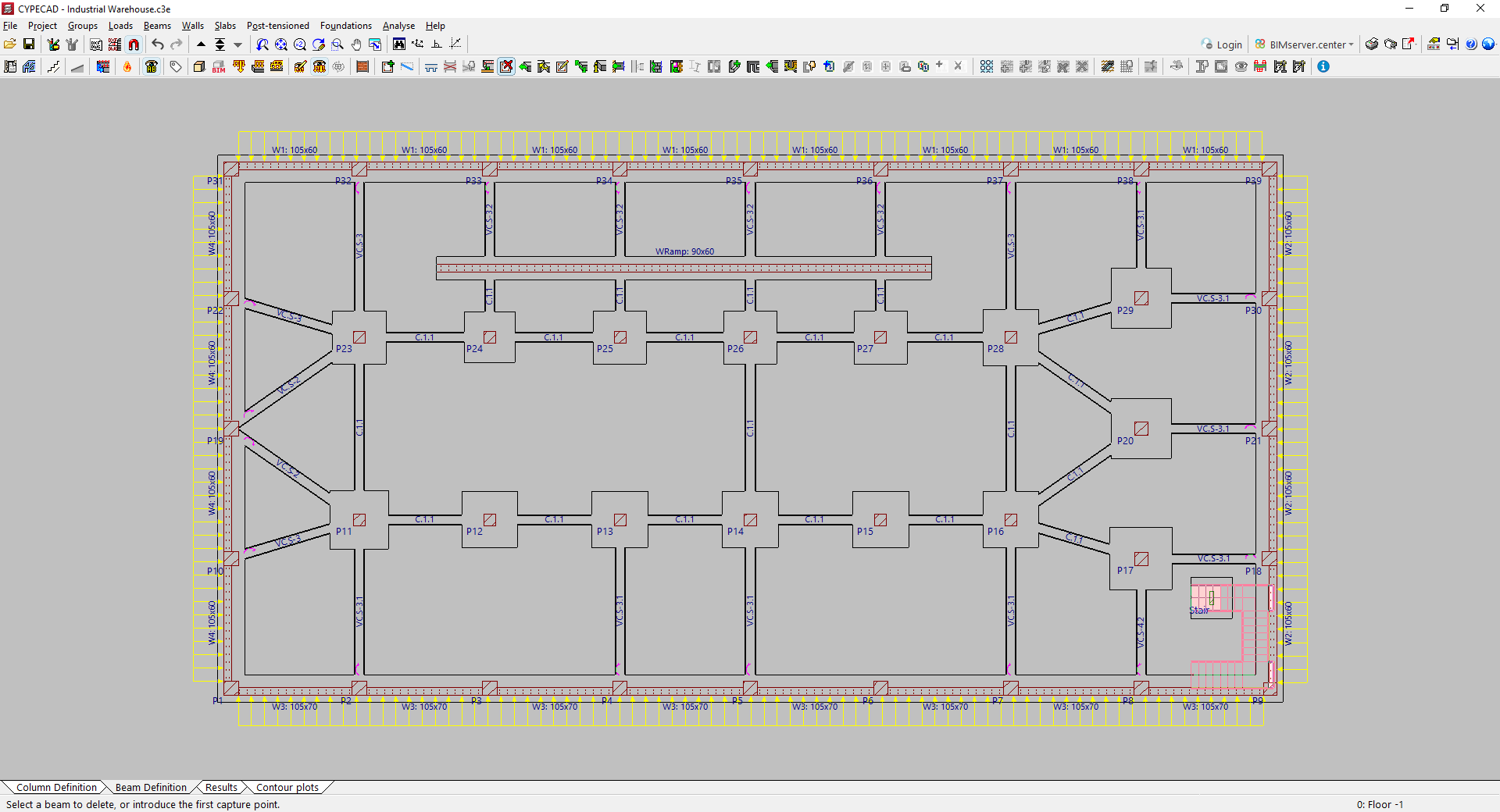
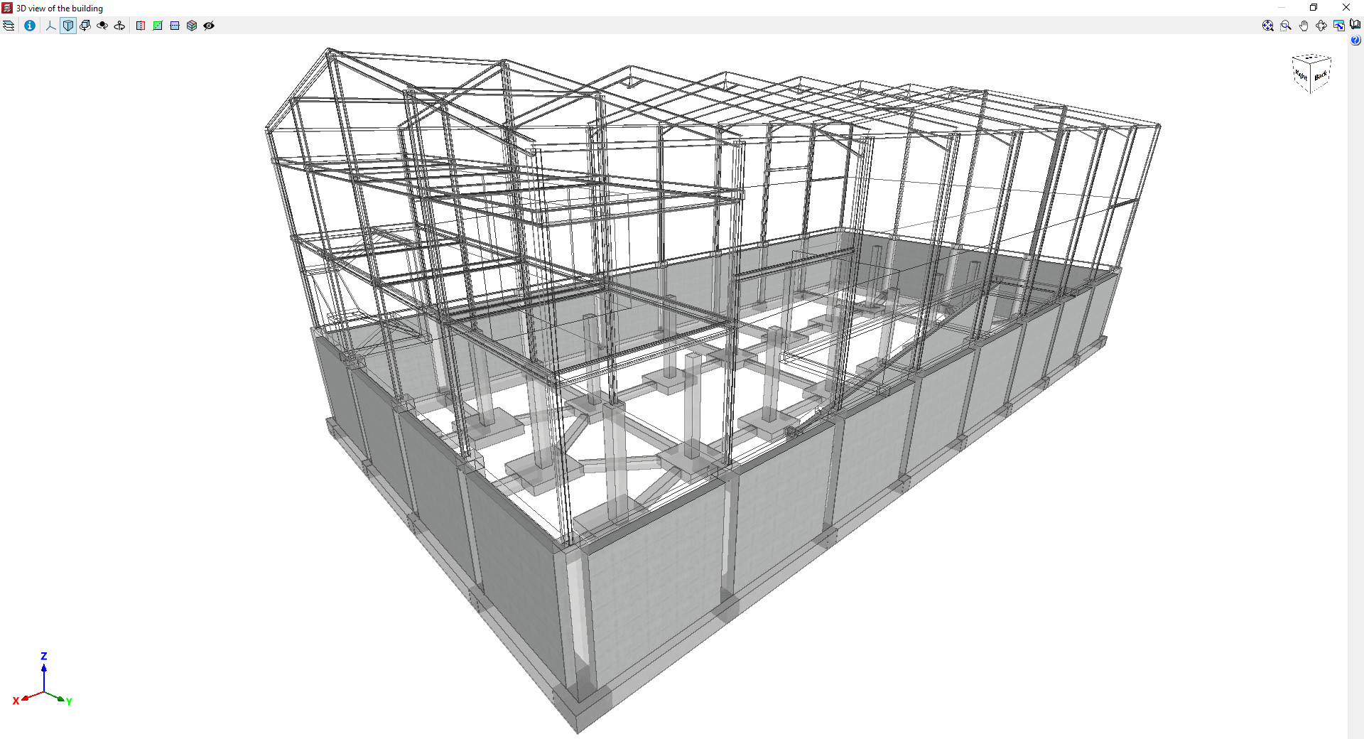
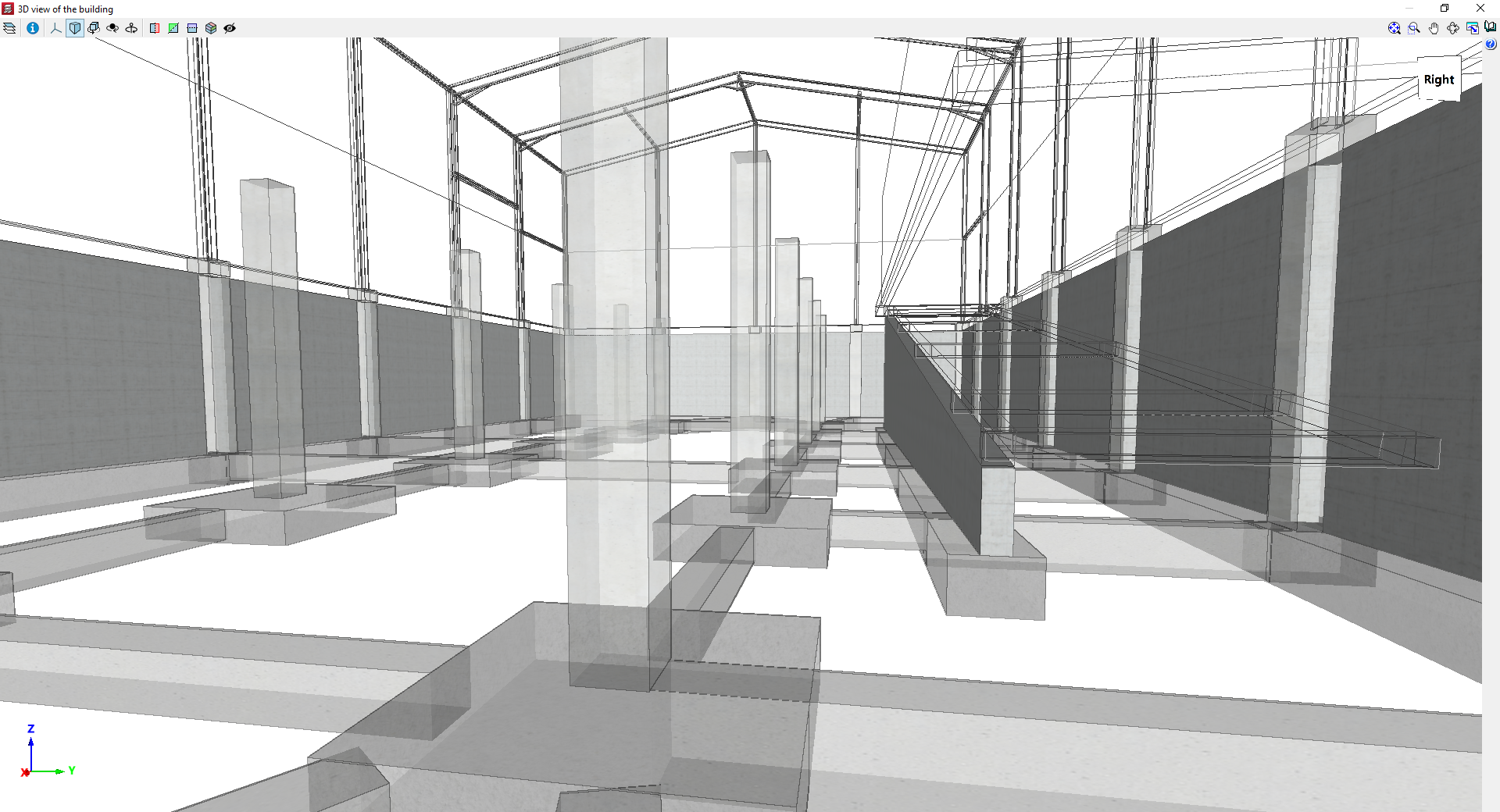
Example model with walls
Inserting reinforced concrete block walls
To add reinforced concrete block walls, open the "Beam Input" tab, select the "Walls" menu, and choose the "Enter wall" option.
Next, select one of the following options at the top:
- "NORMABLOC", if you wish to use concrete block walls from this particular manufacturer’s group (this option is only available if a Spanish concrete standard is selected);
- or "Concrete block wall", if you wish to use generic user-defined concrete block walls.
These two types of walls offer specific options for their configuration, as described below.
The definition of the remaining wall data (such as its reference, its initial floor plan and final floor plan, the pressure conditions acting on the wall and the characteristics of its foundation), as well as the process of laying out the wall on plan, is identical to that carried out for other types of walls, such as concrete or masonry walls.
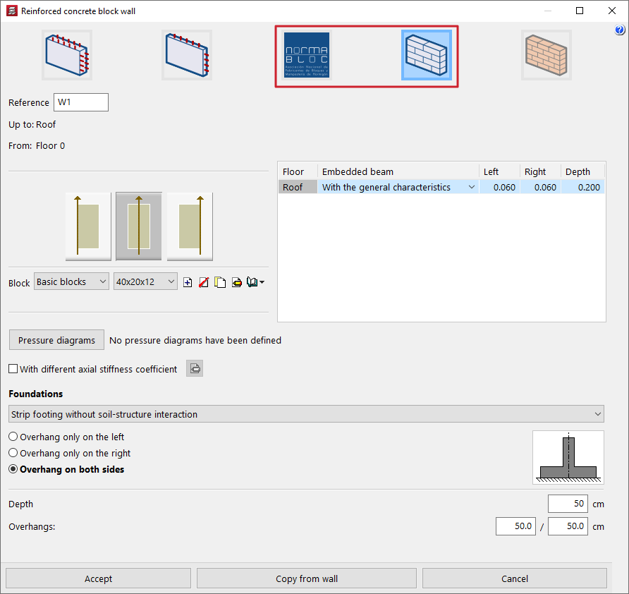
Wall adjustment
On the left-hand side of the panel, the program allows you to specify the wall thickness relative to the line along which the wall is entered on the floor plan (measured from the starting point to the end point entered) by selecting one of the following options:
- The wall is to the right of the line entered
- The wall is centred on the line entered
- The wall is to the left of the line entered
NORMABLOC wall selection
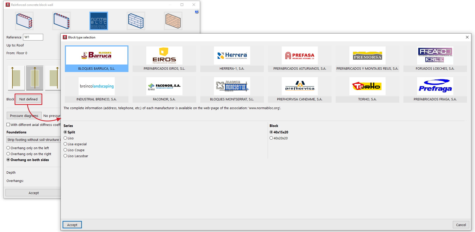
If a "NORMABLOC" wall is selected, clicking the "Block" option opens a window where you must select one of the manufacturers belonging to this association, as well as the specific "Series" and "Block" you wish to use, from the list of products offered by each of them.
Selecting the block type (generic concrete block walls)
If the "Concrete block walls" option is selected, in the "Block" section you can select the series and block from two drop-down menus from those available in the library.
The options on the right allow you to "Create", "Delete", "Copy" and "Edit" series of concrete block walls, as well as carry out the "Management of the section library" of concrete block walls by importing or exporting the data from the created series to files on the hard drive.
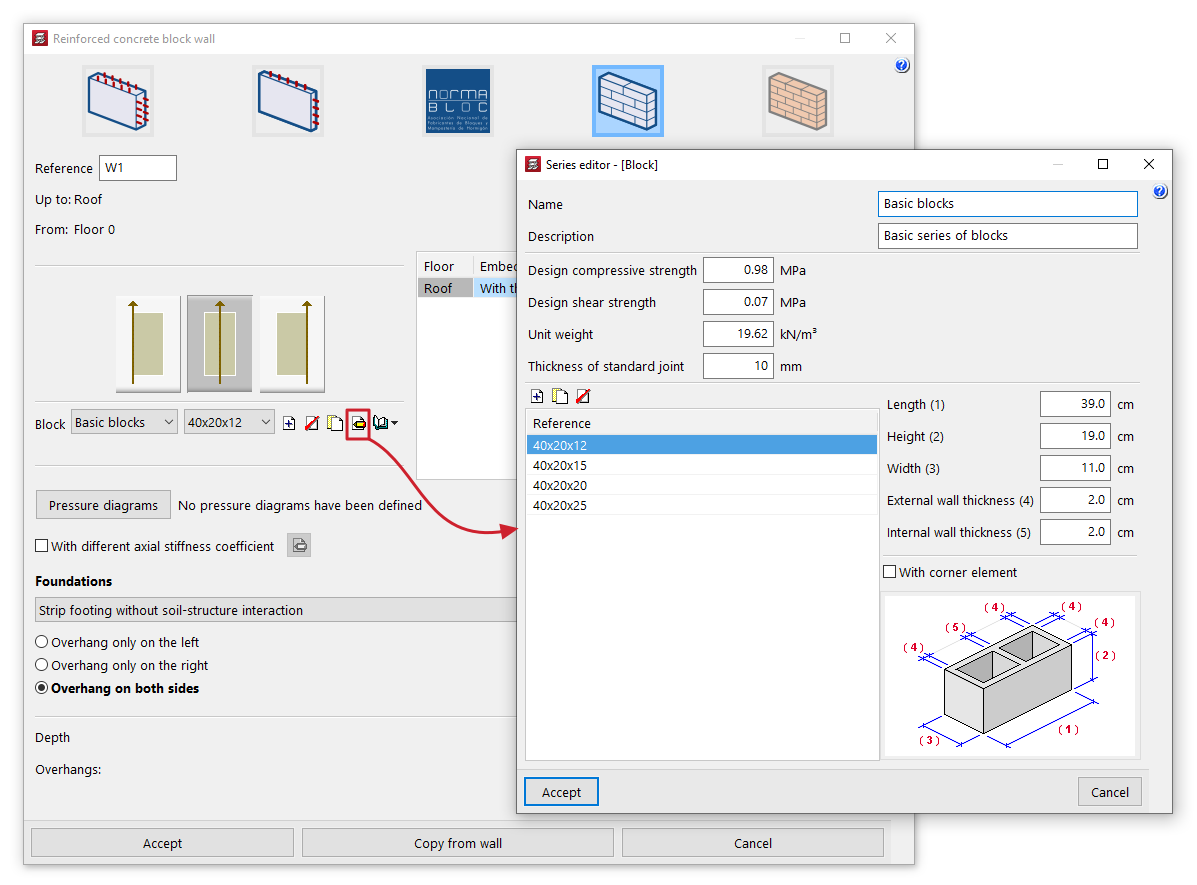
When creating or editing each series, you must define the following parameters:
- Name
Series name. - Description
Series description. - Design compressive strength / Design shear strength
Design compressive and shear strengths of the masonry, based on the gross area. These may be estimated based on the strengths of the components and the mortar, or based on the characteristic strength obtained from tests and reduced by the corresponding safety factor. - Unit weight
Average specific weight at the factory, based on gross area. - Thickness of standard joint
The thickness of the joint between the concrete blocks.
For each series, you must define the list of block types using the table on the left. To do this, when creating or editing each type, enter its "Reference" and the dimensions of each block. These are the actual manufacturing dimensions of the component, without taking into account the joints between blocks in the wall:
- Length
- Height
- Width
- External wall thickness
- Internal wall thickness
The program displays a diagram showing the block's dimensions at the bottom to help users understand these parameters.
Finally, the "With corner element" option allows you to specify that special corner pieces are available for the selected block type. Corner pieces are only necessary when the block's width is not equal to half its length. Otherwise, the corners can be fitted without special elements.
Inserting and managing wall pressure conditions
To define wall pressure conditions, open the "Beam Input" tab, select the "Walls" menu, and choose either "Add Wall" or "Edit".
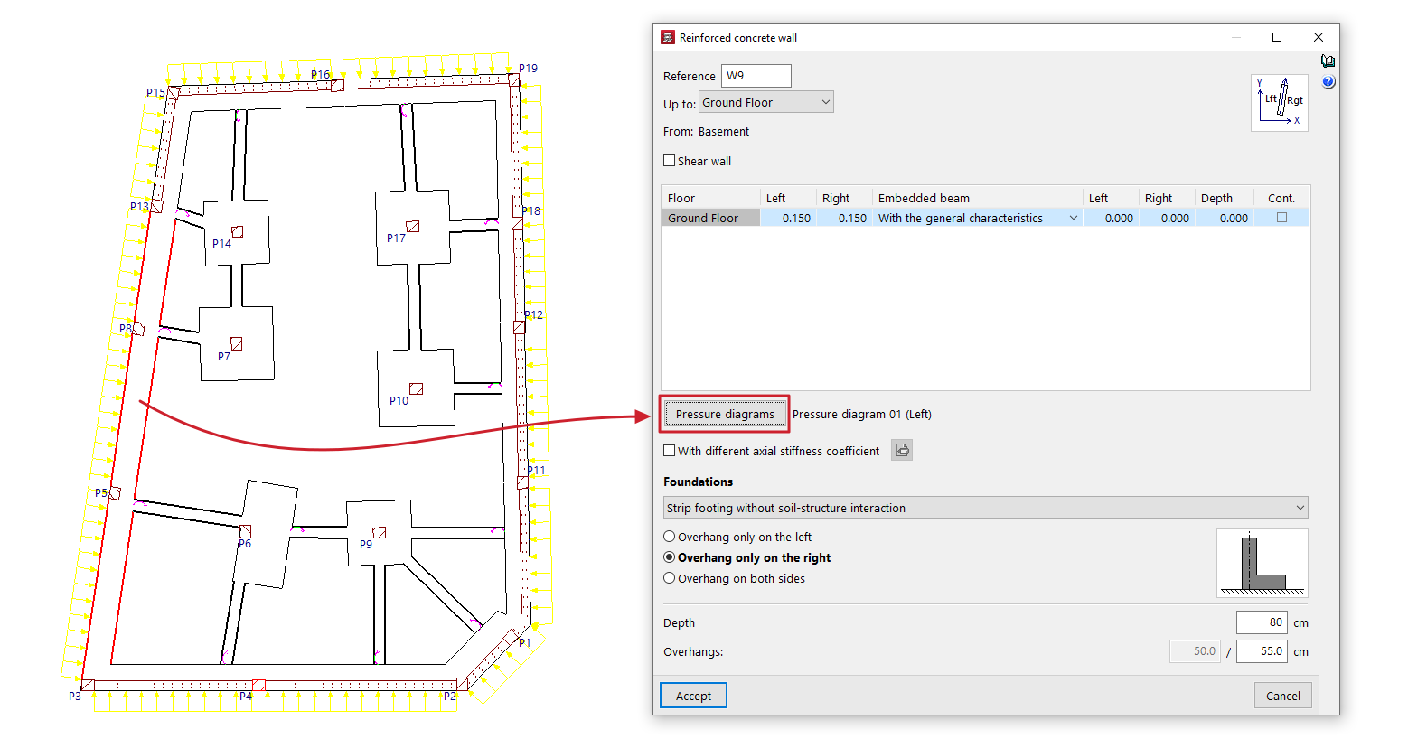
Next, click the "Pressure diagrams" option in the wall editing window to access the interface that allows you to create, manage and apply pressure diagrams to the wall being entered or edited.
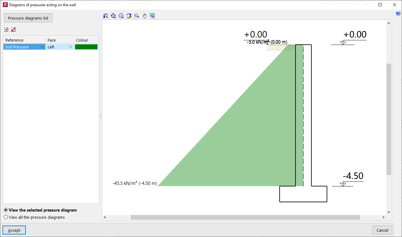
Diagrams of pressures acting on the wall
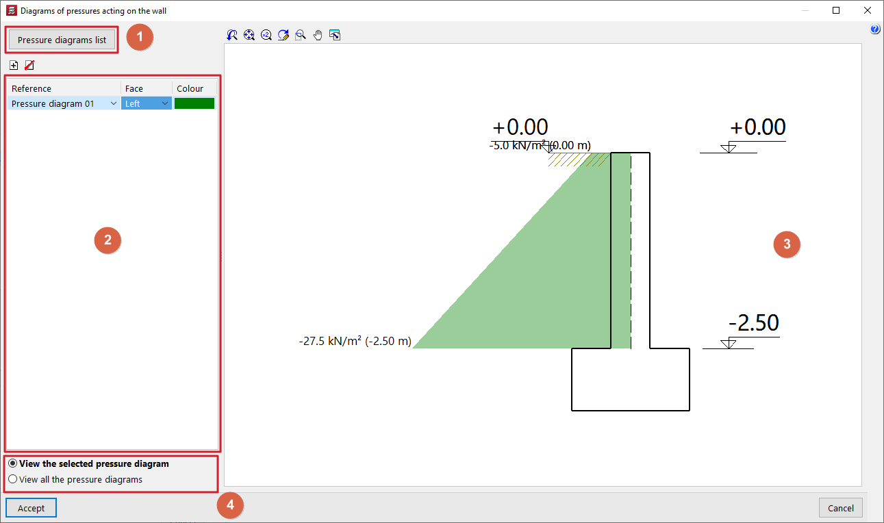
The "Diagrams of pressures acting on the wall" window opens when you click the "Pressure diagrams" option in the wall editing panel and displays the following sections:
- In the top-left corner (1) is the "Pressure diagrams list" option, which opens the window of the same name, where the pressure diagrams available throughout the project are defined and managed.
- On the left-hand side (2), there is a table showing the pressure conditions applied to the wall that is being entered or edited. To apply a pressure condition to the wall and add an entry to the table, click on the corresponding option at the top. The following data is defined for each entry:
- In the "Reference" column, select the pressure diagram you wish to apply from the drop-down menu. To apply a pressure diagram, it must first have been created in the "Pressure diagrams list" window.
- The "Face" column indicates whether the pressure diagram applies to the "Left" or "Right" face of the wall. If the loads are visible, it is possible to check later on the plan view that the pressure diagram has been applied to the correct face of the wall.
- In the "Colour" column, select a colour to be displayed in the sectional view on the right-hand side of the window.
- In the centre-right section (3), a viewport displays the cross-section of the wall being entered or edited, along with a representation of the pressure rule or rules applied to it, coloured according to the selected colours. For each diagram, the pressure values at each elevation are labelled. In addition, the elevations of the wall heights, the fill elevation, the water table and the elevation of the rock layer are shown.
- Using the options in the bottom right-hand corner (4), you can either "View the selected pressure diagram" in the viewer only, or simultaneously "View all the pressure diagram" defined in the table and applied to the wall.
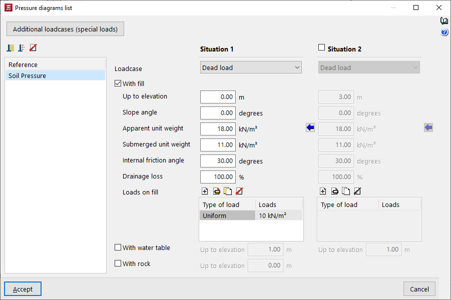
Management of the list of pressure regulations
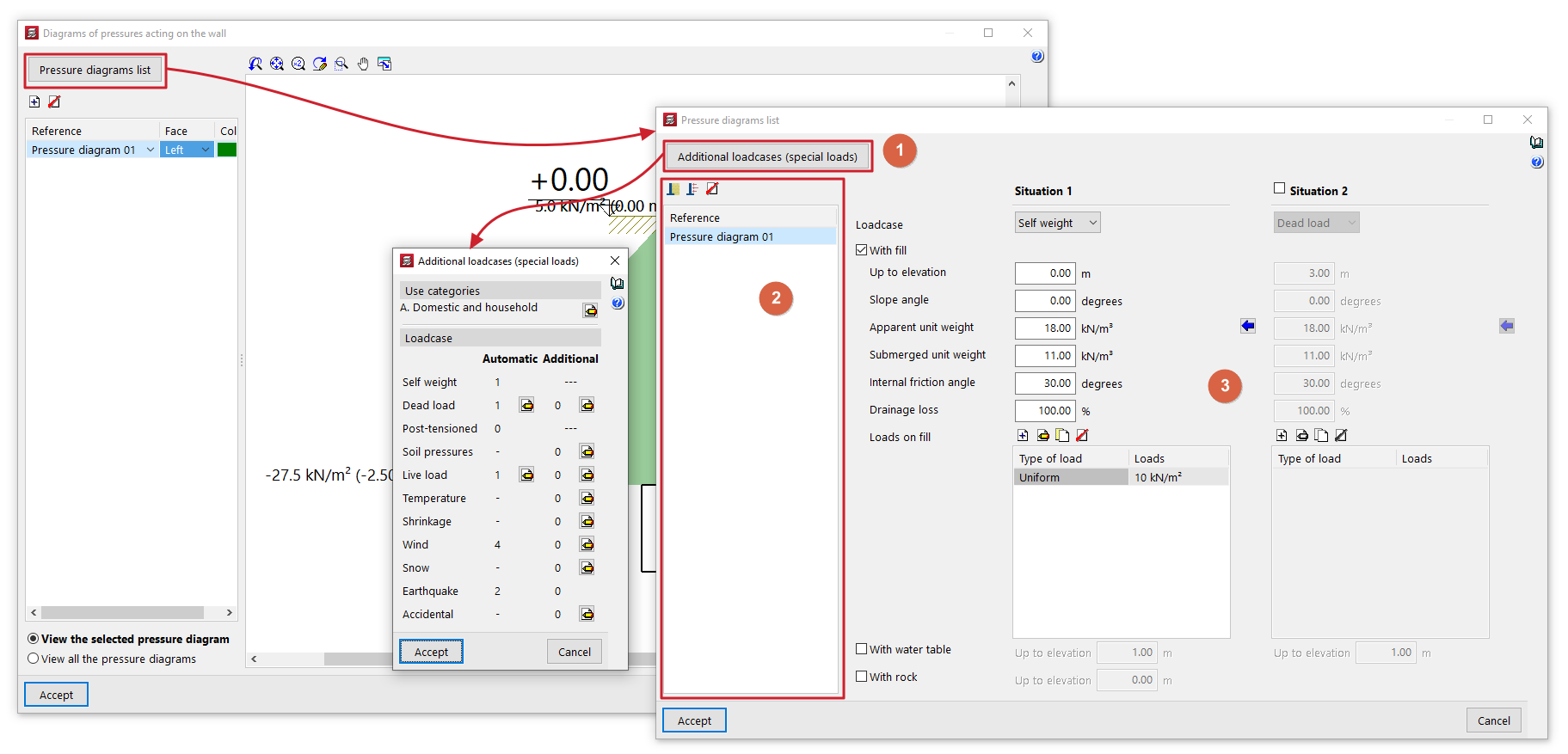
The "Pressure diagrams list" window allows you to create and manage the pressure diagrams available for the project. These diagrams can then be applied to each wall using the options in the "Pressure diagrams on the wall" window.
This window displays the following sections:
- In the top-left corner (1) is the "Additional load scenarios (special loads)" button, which provides direct access to the management panel for the load scenarios available for the project.
- The left-hand side (2) displays the list of pressure diagrams available in the project. To create a pressure diagram and add an entry to the table, click on the "Soil pressure" or "Generic pressure diagram" button at the top. The reference for the diagram can be edited directly in its table cell. It is also possible to delete the selected pressure diagram using the corresponding button at the top.
- The central right-hand section (3) displays the parameters that define the pressure diagram selected on the side. This section varies depending on whether you are editing a "Soil pressure" or a "Generic pressure diagram".
Further down, in the "Project data" section, the generic thrusts and pressures defined for the project will be listed, along with the walls on which these forces act.
Soil pressure on walls
A "Soil pressure" pressure law is defined within the "List of pressure laws" for walls by setting one or two backfill situations, "Situation 1" and "Situation 2". The second is optional and can be enabled or disabled.
Filler situations
Filling conditions correspond to different load conditions throughout the structure’s service life:
- For situation 1, the thrust law will be considered to apply under the conditions associated with situation 1.
- For situation 2, the difference between the forces in situation 2 and the forces defined in situation 1 shall be considered, assuming the conditions associated with situation 2. Therefore, the force law for situation 2 must be greater than the force law for situation 1.
Earth pressure
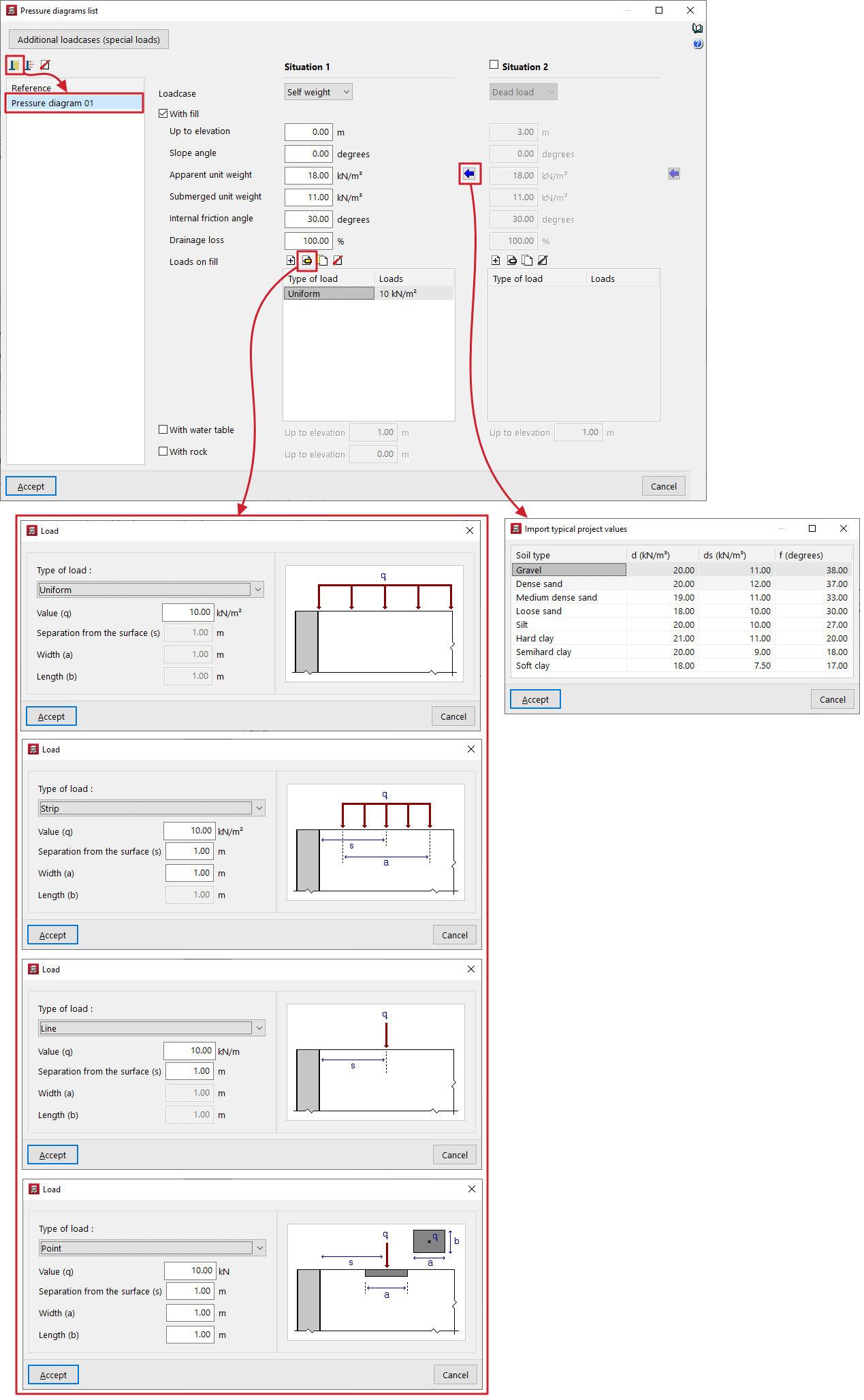
For each fill situation, the following data must be provided in order to define the soil pressure formula:
- First, select the "Loadcase" to which the situation will be linked from those available in the drop-down menu.
- The "With fill" checkbox can then be ticked to indicate the presence of a backfill defined by the following parameters:
- Up to elevation
Elevation in general coordinates of the top of the fill. - Slope angle
If a value is entered for the slope angle, the embankment will have a certain angle of inclination on its surface. This angle is considered to be zero when the surface of the embankment is horizontal, whilst it is positive for a sloping embankment. The minimum value for the slope angle is 0 degrees, whilst the maximum value is limited to that of the soil’s internal friction angle. - Apparent unit weight
Bulk density of the fill material. - Submerged unit weight
Submerged unit weight of the soil. This value enables the assessment of soil pressures below the water table. - Internal friction angle
The internal friction angle of the soil, expressed in degrees. This value can range from 35 to 45 degrees for sandy gravel, compacted sand or rock fill, and from 30 to 35 degrees for loose sand. - Drainage loss
The presence of drainage in the wall can be considered by entering a specific percentage of drainage. The program reduces the total value of the hydrostatic pressure acting on the wall face by the specified percentage. For example, if the percentage of drainage is 100%, even if a water table is defined, the hydrostatic thrust is zero. - Loads on fill
This table allows you to add different types of loads to the fill:- Uniform
Only its "Value (q)" is entered as a surface load. - Strip
Enter its "Value (q)" as a surface load, the "Separation from the surface (s)" from the centre of the strip, and the "Width (a)" of the strip. - Line
Enter the "Value (q)" as a linear load and the "Separation from the surface (s)". - Point load
Enter the "Value (q)" as a point load, the "Separation from the surface (s)" from the centre of the load application, and the "Width (a)" and "Length (b)" of the area where the load is applied.
- Uniform
- Up to elevation
- Further down, the "With water table" box allows you to specify the elevation, in general coordinates, at which the water table is located. Hydrostatic pressure will be taken into account below the water table.
- Finally, the "Rock" checkbox allows you to define the upper level of the rock layer in general coordinates. The program will not apply thrusts below this level.
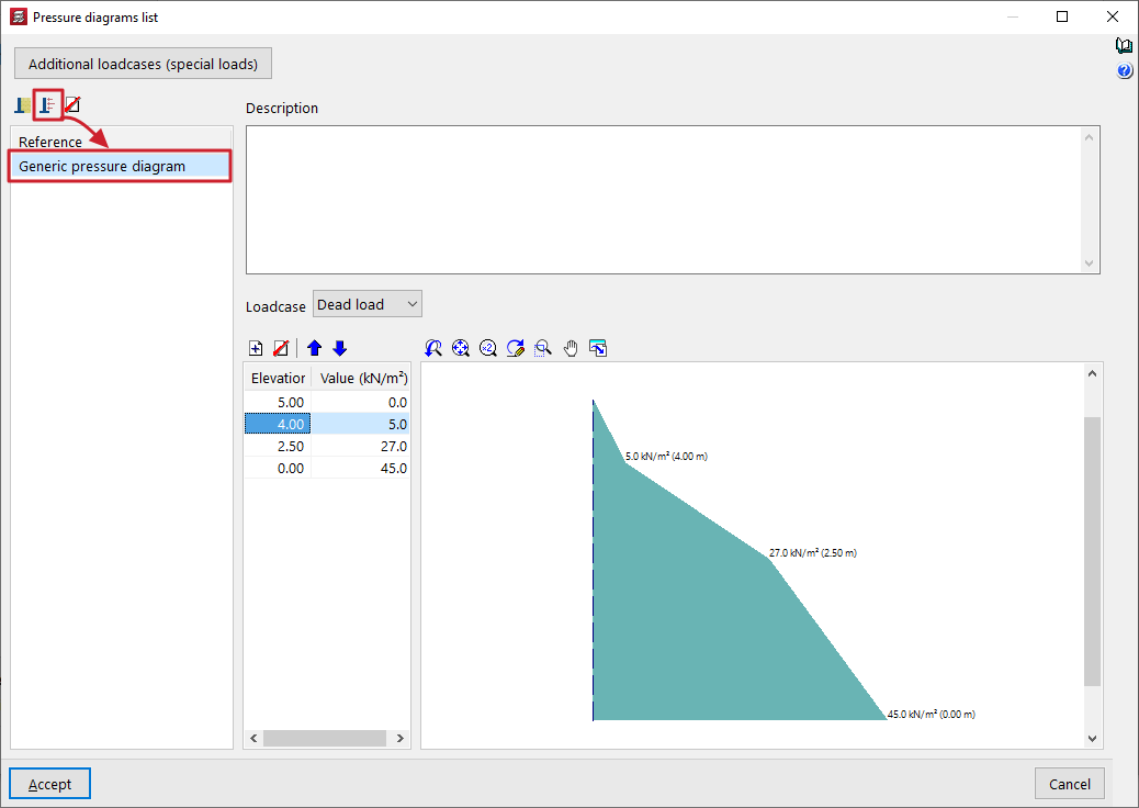
Generic pressure diagram for walls
The introduction of a "Generic pressure diagram" within the "Pressure diagram list" for walls allows pressure diagrams to be freely defined by directly entering the values that define them from point to point.
To define a generic pressure diagram, you need to enter the following data:
- At the top of the panel, you can enter text for "Description".
- Next, select the "Loadcase" to which the rule will be applied. Any load case can be selected; for example, this option can be used to specify the wind pressure on a wall.
- Finally, in the table below, you must enter pairs of points that define the diagram, specifying a "Value" (in units of force per area) for each "Coordinate" (in general site coordinates).
Right-clicking on the cells in this table brings up a context menu that allows you, amongst other options, to "Copy selected rows" or "Paste from clipboard", which is useful if you have this data in other spreadsheets.
The program displays the geometry of the pressure diagram in the viewer on the right-hand side.
CYPECAD - Inserting walls on other walls
The "Insert walls on other walls" option in the "Walls" menu of the "Beam input" tab allows you to insert a wall on top of an existing one.
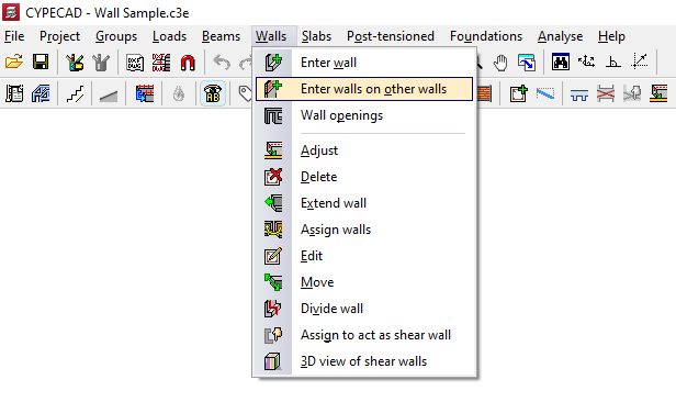
To do this, you need to position yourself on the top floor of a wall or several walls that have already been inserted and click on the option.
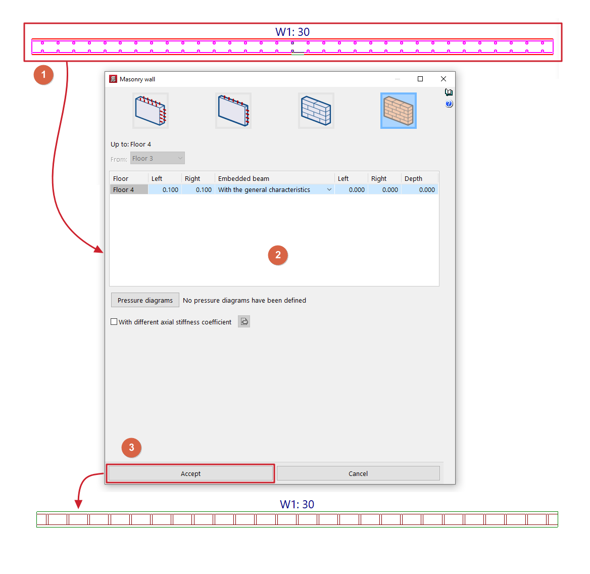
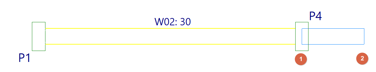
Next, select the previous walls by clicking on them one by one with the left mouse button or by using a capture window (1). To finalise the selection, click the right mouse button.
This opens a window where you can define the characteristics of the new wall or walls to be inserted (2), including their final floor. The "From" parameter, which defines the initial floor of the new wall, will be locked and its information will have been taken from the final floor of the lower wall.
After clicking "Accept" (3), the new walls will be inserted, taking the position of the lower walls on the floor plan.
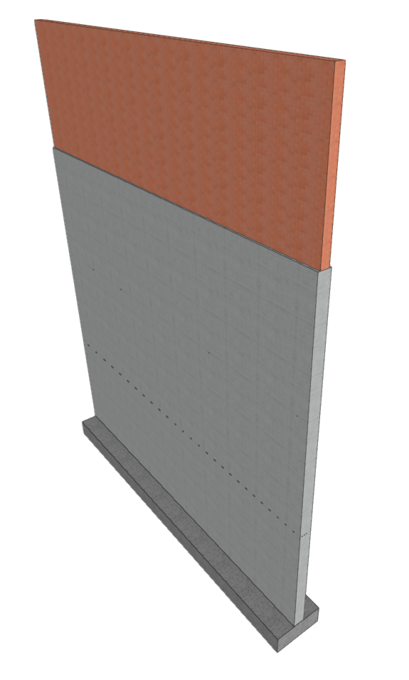
This option allows you to insert walls on top of others of different types or materials, making it possible, for example, to define reinforced concrete walls on lower floors and masonry walls that rise above them.
| Note: |
|---|
| The program will not allow you to insert a reinforced concrete wall on brick or block masonry walls. |
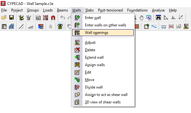
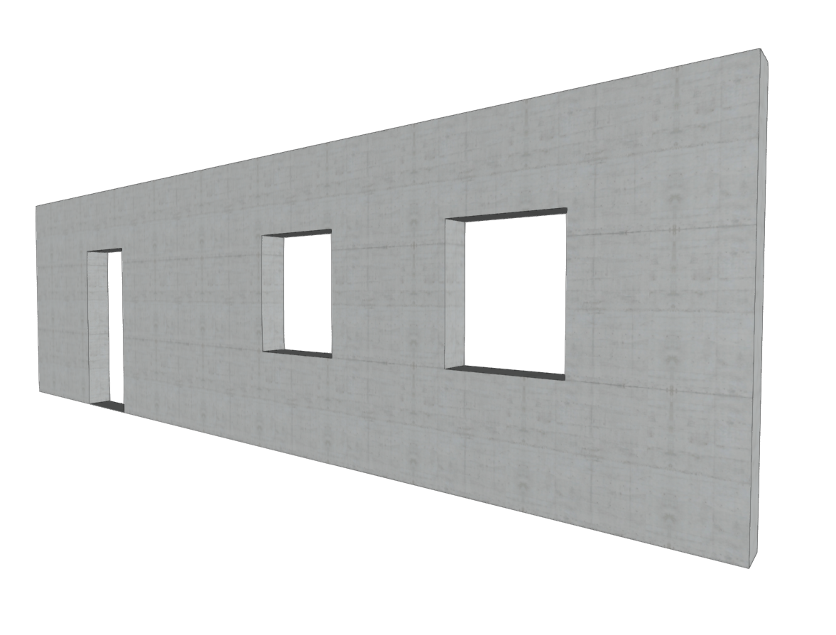
Inserting wall openings
The "Wall openings" option in the "Walls" menu of the "Beam entry" tab allows you to enter and edit doors and/or windows in reinforced concrete walls, concrete block walls, and masonry walls.
| Note: |
|---|
| In order to insert the openings in the correct place, you will need to view the floor plan of the section of the wall between the floors where you want to open the hole. For example, if you want to insert a door or window in a wall between floor 1 and floor 2, you must view floor 1. Openings cannot overlap. It is also not advisable to insert openings very close to each other in order to ensure correct discretisation across the entire surface of the wall. |
The options available in this menu are as follows:
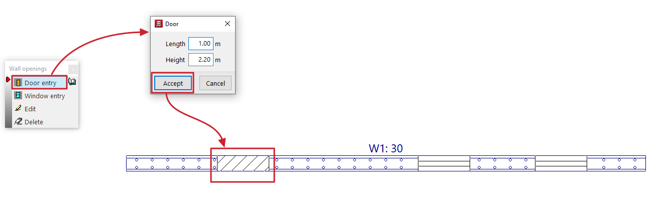
Inserting doors
This allows you to open a door in a wall.
The door is defined by the values for "Length" and "Height" entered in the dialogue box that appears when this option is selected.
After clicking "Accept", position the door on the wall by clicking and dragging one of its ends with the left mouse button on the floor plan.
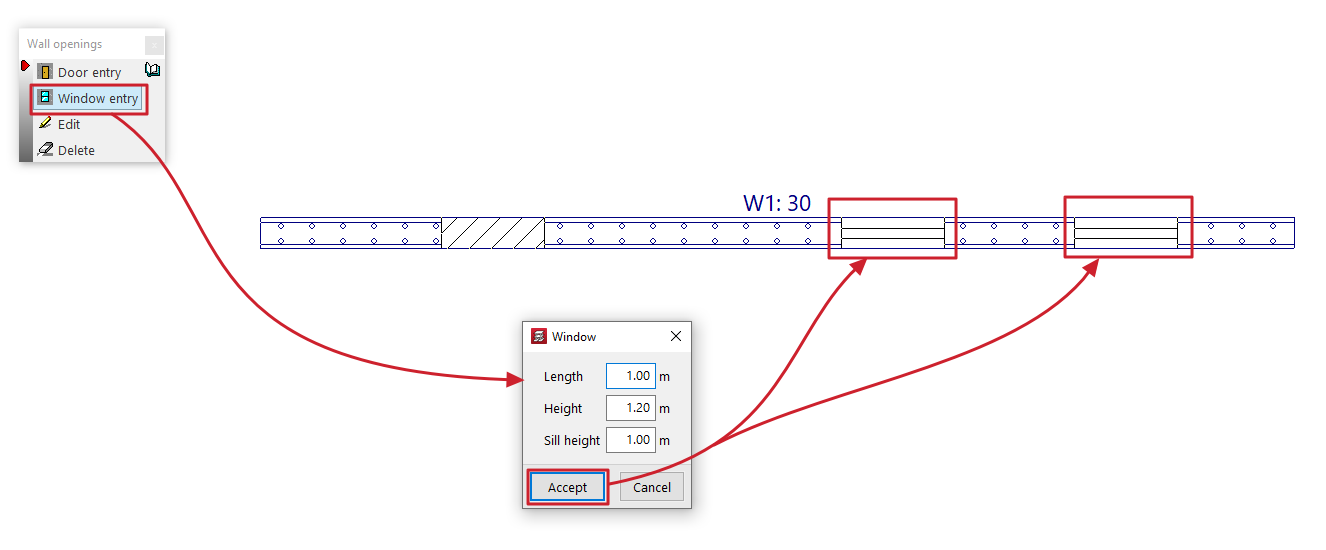
Installation of windows
This allows you to open a window in a wall.
The window is defined by the values for "Width", "Height" and "Sill height" entered in the dialogue box that appears when this option is selected.
After clicking "Accept", position the window on the wall by clicking the left mouse button on the floor plan to mark the position of one of its corners.
Edit
This allows you to edit the geometry of a door or window that has already been added to a wall.
To do this, simply select the opening on the floor plan and edit its details in the dialogue box that appears when you click on it.
Delete
This allows you to delete doors or windows previously added to the walls by selecting them one by one with the left mouse button or by using a selection area.
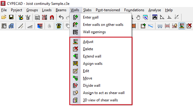
Adjustment and configuration tools in the "Walls" menu
The program offers the following tools for adjusting and configuring walls in the "Walls" menu, within the "Beam input" tab:
- Adjust
- Delete
- Extend wall
- Assign walls
- Edit
- Move
- Divide wall
- Assign to act as shear wall
- 3D view of shear walls
Each of these tools is described below:
Adjust
The "Adjust" option allows you to adjust the position of a wall by aligning its faces or axis with the faces or axes of nearby columns or screens, as well as with lines from a DXF/DWG template, contours, lines of maximum slope, or intersection lines of sloping wall sections.
- To adjust one end of the wall, left-click on it, move the cursor close to the face you wish to adjust, and keep the cursor outside the wall.
- To adjust both ends of the wall at the same time—that is, to adjust the entire wall—click in the centre of the wall, moving the cursor close to the relevant face whilst keeping it outside the wall.
- You can also adjust the axes. To do this, left-click on the edge or the centre of the wall whilst keeping the cursor inside the wall.
- If you wish to snap to a DXF or DWG template or to an outline, you must first select the "Template object snaps" option from the toolbar and, in the dialogue box that appears, choose the "Closest" snap. When you do this, the "Adjust" option will fit the walls to the DXF or DWG template lines or to the outlines, rather than to the faces or axes of columns, until snapping is disabled.
- If inclined planes have been defined previously, right-clicking will bring up a dialogue box containing the "Adjust to intersection of planes / line of maximum slope" option. Selecting this option allows you to do the following:
- If a wall is intersected by two sloping floor slabs, it is possible to align the wall with the line where the two planes of these floor slabs intersect.
- If a wall is defined on an inclined plane, it is possible to align the wall with a line passing through its centre that follows either the direction of the maximum slope of the plane or the direction perpendicular to the maximum slope of the plane, whichever is closest to the wall’s current direction.
Delete
You can use the "Delete" option to remove any wall you have added.
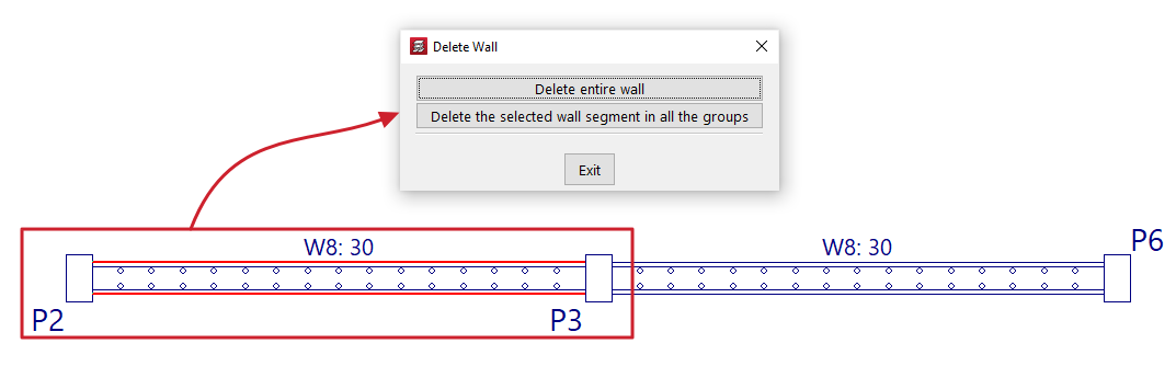
If a wall is divided into several sections (for example, where a beam or wall meets another wall), clicking on a wall brings up a dialogue box with two options:
- Delete entire wall
This option deletes the entire selected wall, including all sections in all groups. - Delete the selected wall segment in all the groups
This option removes only the specified section of wall from all groups, leaving the remaining sections intact.
Extend wall
Using the "Extend wall" option, you can move the end of a wall along its axis.
Select the wall using the left mouse button in the floor plan view, then click the left mouse button in the floor plan to mark the new desired position for one of its ends.
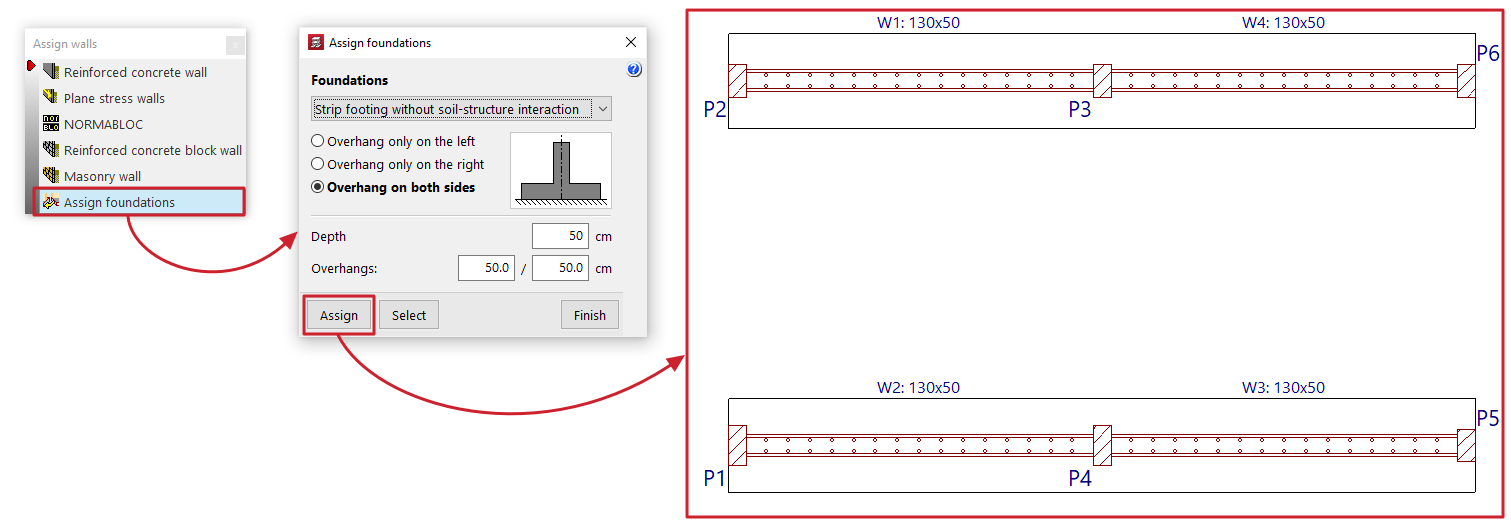
Assign walls
The "Assign walls" option allows you to copy the properties of the selected wall to other walls in the current group.
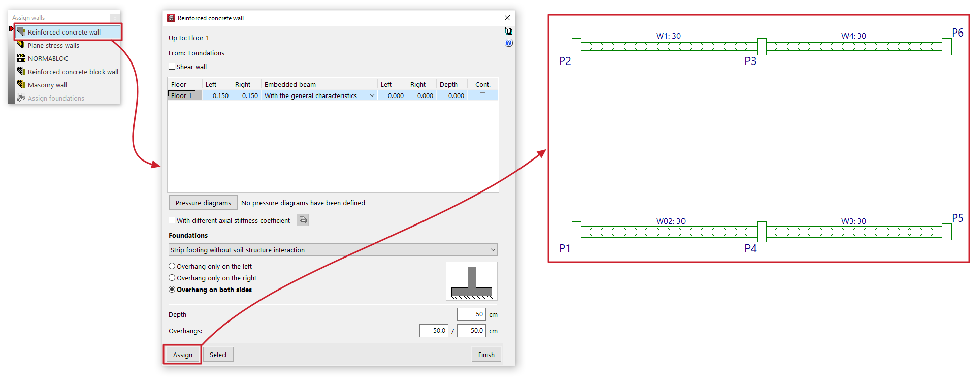
Clicking on this option opens a dialogue box where you can select the type of wall from those available ("Reinforced concrete wall", "Plane stress walls", "NORMABLOC", "Reinforced concrete block wall" or "Masonry wall") in order to configure the characteristics to be assigned.
In addition, the "Assign foundation" option is available if any walls originate from the visible floor group. This option allows you to configure a wall foundation type that can subsequently be applied to the selected walls.
At the bottom, the "Assign" option allows you to select the walls in the floor plan to which the data will be assigned (whether the characteristics of the selected wall type or the configuration defined for its foundation), whilst "Select" allows you to extract the information to be assigned by selecting a specific wall in the floor plan. The "Finish" option allows you to complete the operation without making any changes.
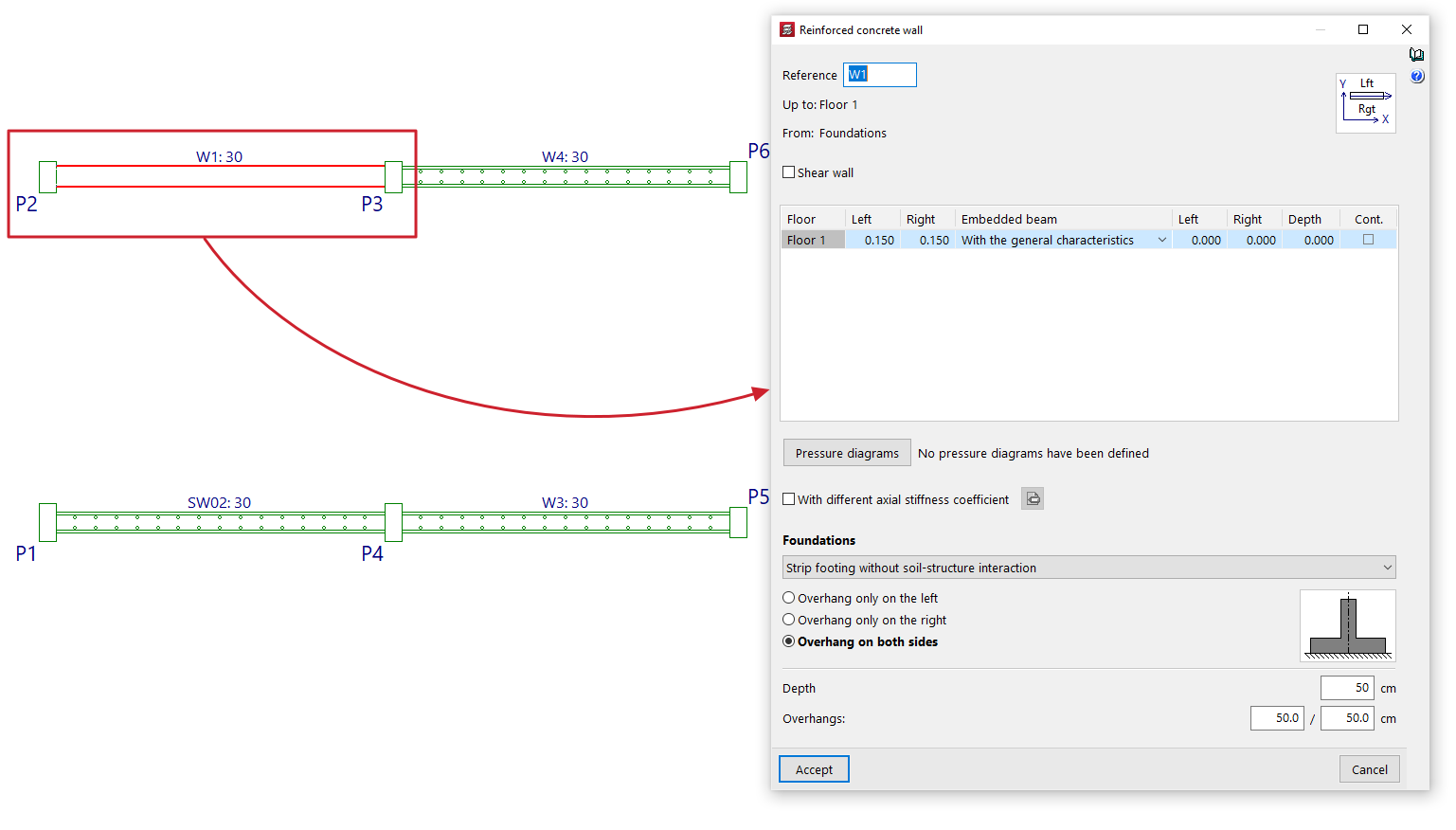
Edit
Using the "Edit" option, you can edit and modify the properties of the selected wall on the floor plan, as well as its foundations.
The program will open the wall definition window so that you can enter the desired settings, which will be applied to the wall when you click "Accept".
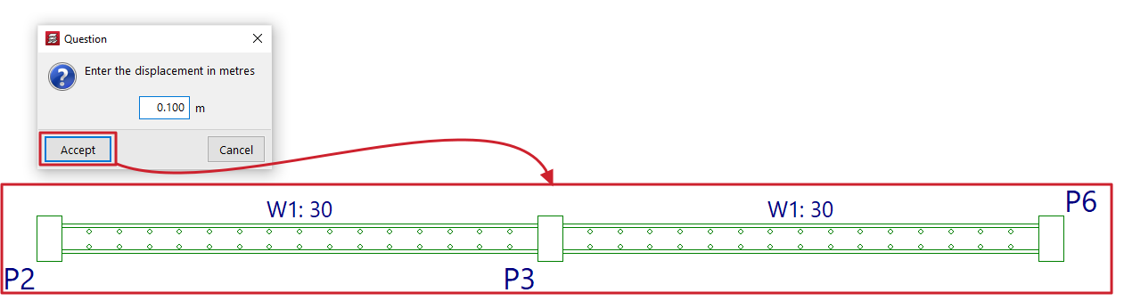
Move
The "Move" option allows you to move one end of a wall (whilst keeping the other end fixed) or to move the entire wall in parallel, based on a specified displacement value.
When you select this option, the message bar at the bottom of the program interface will display the value for "Current displacement" – the displacement that will be applied. You can change this value by right-clicking and entering the new displacement value in the dialogue box that opens.
Next, to move the wall, place the cursor near one end or the centre of the wall and click on the side towards which you want to move it, depending on whether you want to move just one end or the entire wall in parallel.
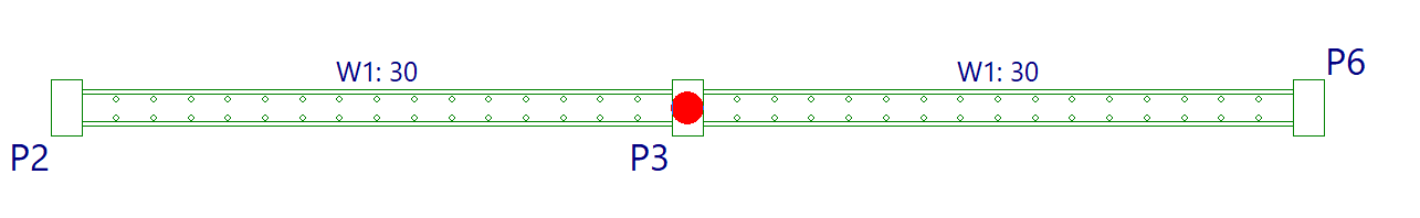
Divide wall
The "Divide wall" option allows you to split a wall into several sections.
To do this, after clicking on the option, select the point on the wall where you want to create the division and click the left mouse button.
A split may be necessary, for example, if you wish to change sections.
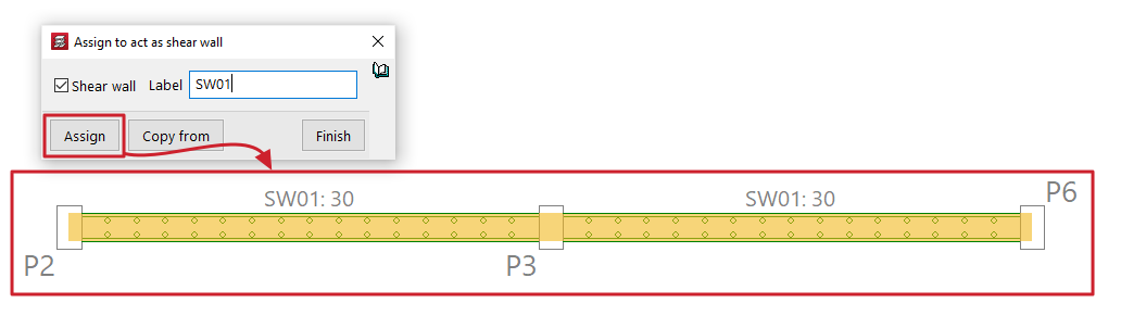
Assign to act as shear wall
The "Assign to act as shear wall" option allows you to assign the shear wall function to one or more walls simultaneously.
Selecting this option opens a dialogue box where you must tick the "Shear wall" box and enter a "Label" for the wall. Clicking "Assign" will assign that label and the shear wall function to the selected walls on the floor plan.
Clicking on "Copy from" will allow you to extract the information from the selected wall on the floor plan, whilst "Finish" completes the operation.
All walls with the same label are grouped together to form a shear wall.
| Nota: |
|---|
| CYPECAD designs the reinforcement for shear walls by arranging the reinforcement to withstand the forces imposed by the applied forces. It does not perform specific checks for shear walls, nor does it generate the reinforcement layouts required by standards for this type of element. To design them correctly, you must link the job to a BIMserver.center project and, after exporting the results from CYPECAD, create a new file in the StruBIM Shear Walls program and link it to the same project. In the StruBIM Shear Walls program, you can design and verify reinforcement in accordance with all the requirements of the selected standard. |
3D view of shear walls
Displays a 3D view of the reinforced concrete walls in the model. Each shear wall will be shown in a different colour to distinguish it from walls that have not been defined using the shear wall function.
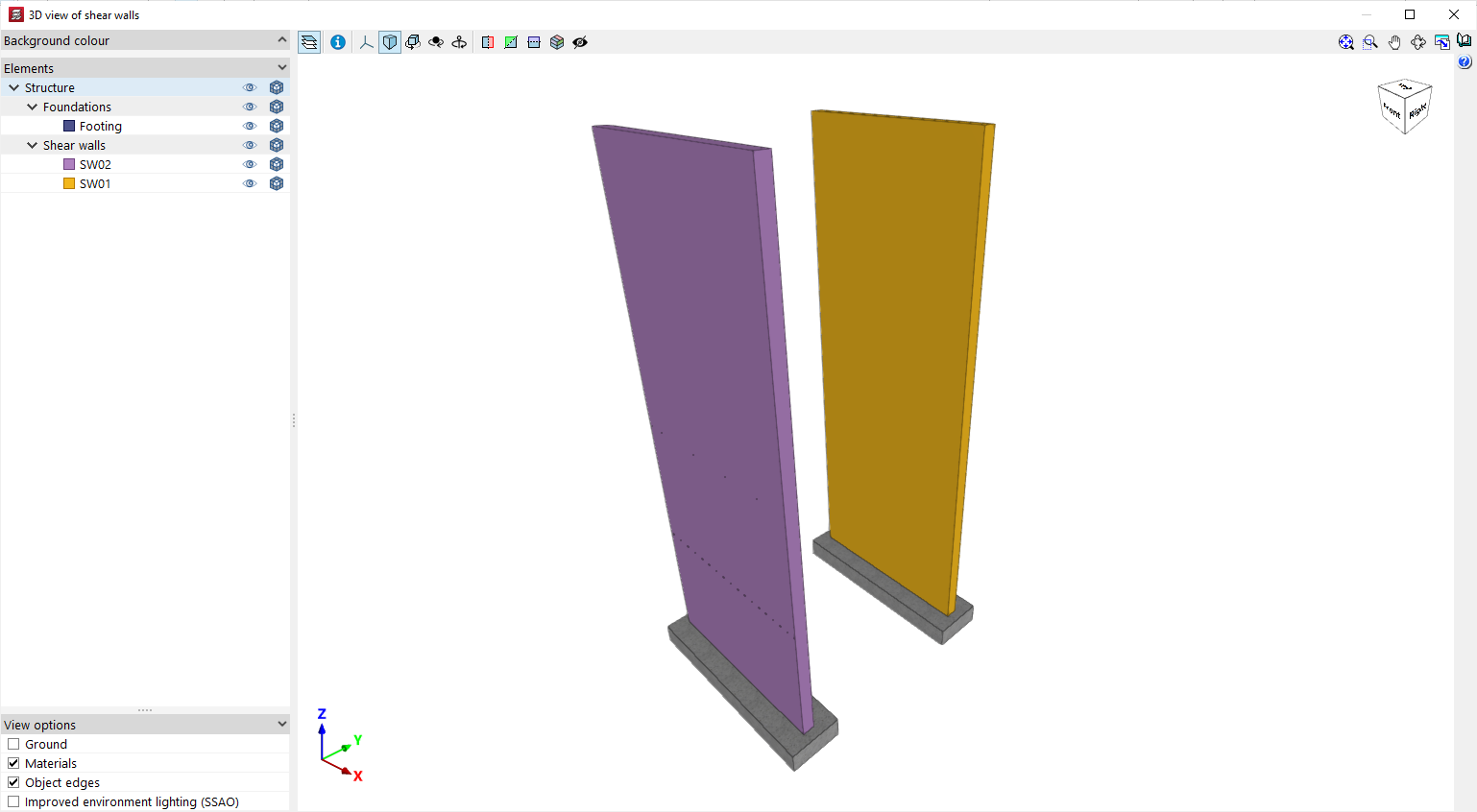
Table of contents
Complete your tour of CYPECAD by exploring the other available sections:
- Introduction
- Introduction and creating new jobs
- General data configuration
- Defining floors and groups of floors and inserting columns, shear walls and starts ("Column input" tab)
- Inserting beams, walls, floor slabs, foundation elements and special elements, and structural analysis (the "Beam Input" tab):
- Checking analysis results and editing elements (the "Results" tab):
- Options on the "Contour plots" tab
- Printing documents and exporting data
- More information:
- General features of CYPECAD