
Introduction
CYPELUX is a program developed for the lighting design of normal and emergency lighting systems as well as daylight illumination and evaluates them in accordance with the codes from different countries and regions or using checks with customised parameters.
In addition, justification of daylighting requirements for LEED v4 certification can be provided.
The app can import the necessary information extracted from other Open BIM tools, so that the architectural models can be used as the geometrical basis for the development of the lighting system.
The program also includes Radiance software developed by the Lawrence Berkeley National Laboratory.
Workflows supported by the program
As CYPELUX is an Open BIM tool and is connected to the BIMserver.center platform, it offers different workflow options.
Data entry
Free modelling / with templates
- Designing the system by entering it freely in CYPELUX.
- Defining system in CYPELUX based on DXF/DWG, DWF templates or images (.jpeg, .jpg, .bmp, .wmf).
Importing BIM models
If the CYPELUX job is linked to a BIM project on the BIMserver.center platform, the following actions can be carried out:
- Importing the model with the building geometry. This allows users to generate the building’s floor plan and to enter the system’s elements based on this geometry. Users can also import the zones based on the spaces read from the BIM model and the layout of the glazed openings. The following options are available:
- Importing models designed in IFC Builder.
- Importing models designed in CYPE Architecture*.
- Importing models in IFC format with IFC Uploader* (generated by CAD/BIM programs such as Allplan, Archicad and others).
- Importing models designed in Autodesk Revit with the Open BIM - Revit Plugin.
*Only if daylight does not need to be calculated. - If IFC Builder or CYPE Architecture generates the architectural model, users can also import the DXF or DWG templates contained in that model, or those generated by the same program (from the building elements entered) when a model is exported to the BIM project.
Data output
- Exporting reports to HTML, DOCX, PDF, RTF and TXT formats.
- Exporting drawings to DXF, DWG and PDF formats.
- Exporting the bill of quantities to FIEBDC-3 format.
- Exporting the information generated with CYPELEC Electrical Mechanisms to the BIMserver.center platform using IFC and GLTF formats. The information can then be viewed by authorised project participants. The information generated by CYPELUX can be used by the following programs:
- CYPETHERM LOADS
This program imports the installed lighting power in the building's spaces. - CYPELEC Distribution
This program imports luminaires and automatically assigns and generates the corresponding receivers in their position.
- CYPETHERM LOADS

Work environment
The CYPELUX interface has three tabs with different work environments: "Installation", "Bill of quantities" and "Sheets". These environments are similar to those of other CYPE tools and have a system of dockable windows that can be customised to adapt the workspace to the needs of the project.
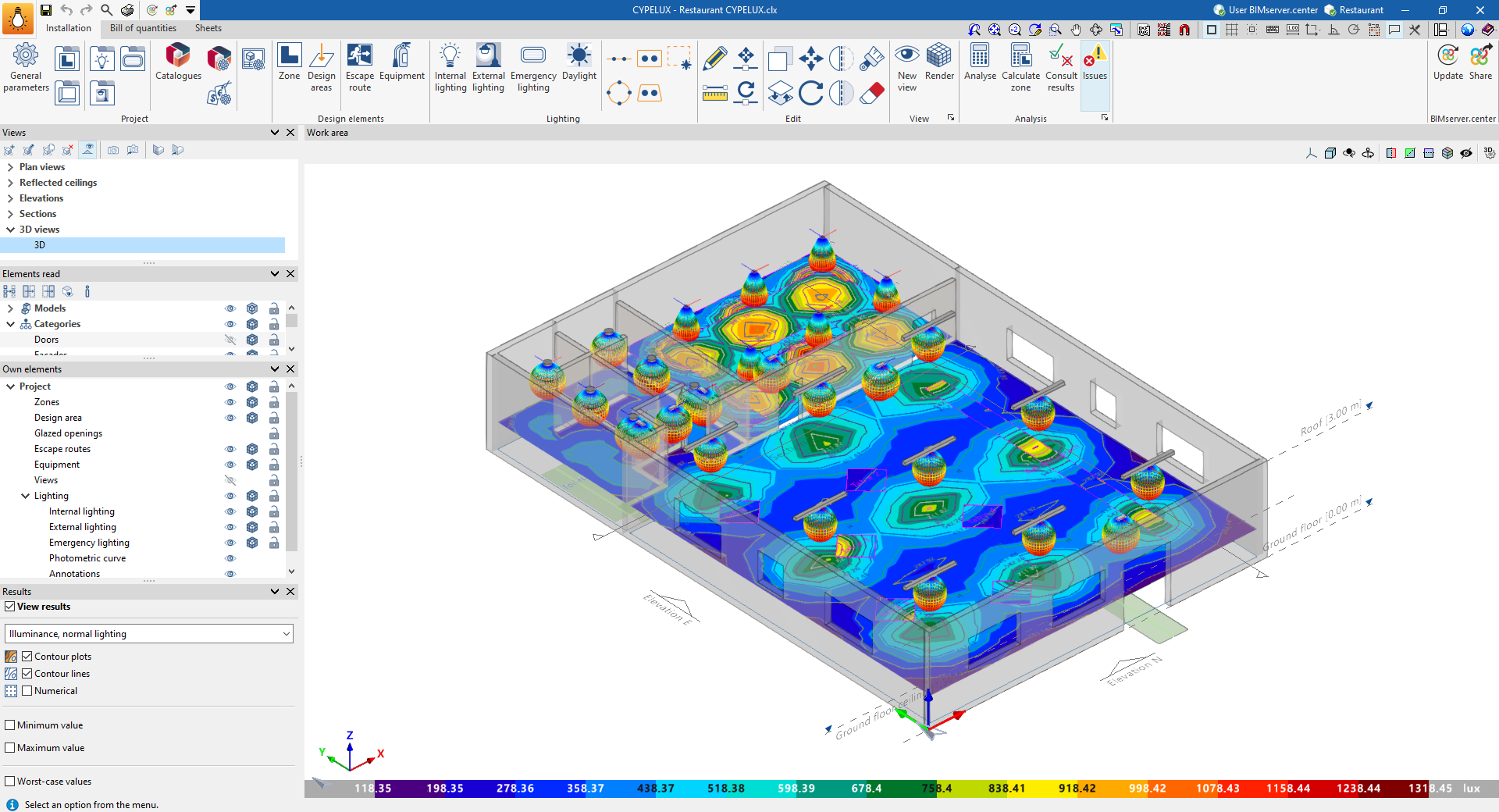
"Installation" tab
The "Installation" tab has a work environment that allows the design of the installation to be carried out quickly and easily, both in a 3D view and in any type of 2D view (such as floor plans and elevations). As a result, the elements in the system can be entered using the most appropriate view at any given time.
This tab displays the following:
- A top toolbar containing the tools for: managing the project parameters, type libraries and catalogues, and configuring the generation of sheets; entering the spaces, design areas and safety or protection elements to be illuminated; entering and editing the luminaires and configuring the daylight calculation, including the automatic distribution tools; accessing the editing tools; creating views and renderings; and analysing and checking the lighting installation.
- The work area, on the right of the screen, where the above-mentioned elements are entered, edited and displayed.
- Finally, on the left side panel, there are several panels with tools for defining the views of the project, managing the visibility of the elements read and own elements, and activating the display of the analysis results.
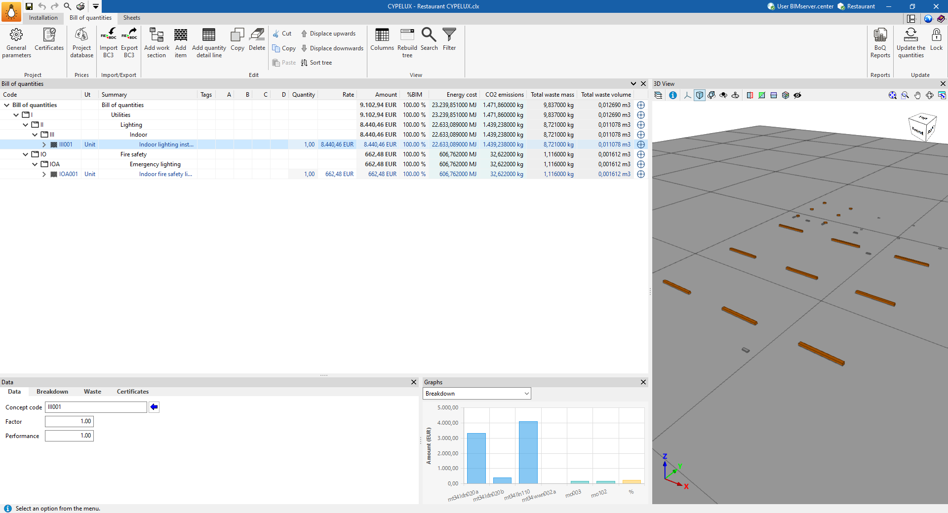
"Bill of quantities" tab
On the other hand, the "Bill of quantities" tab is used to manage the bill of quantities of the lighting installation, and displays the following:
- A top toolbar containing the tools for creating and editing the bill of quantities, as well as those for managing and creating reports.
- A graphic window with its own toolbar, located on the right-hand side, in which it is possible to view the different elements of the job.
- A specific area for structuring the bill of quantities, on the left-hand side.
| Note: |
|---|
| Unlike the implementation of the "Bill of quantities" tab in other CYPE apps, in CYPELUX there is no need to establish a correspondence or mapping between the elements measured on the design model and the bill of quantites concepts. This is because CYPELUX has the capacity to generate job units automatically from the lighting from the Open BIM Database. |
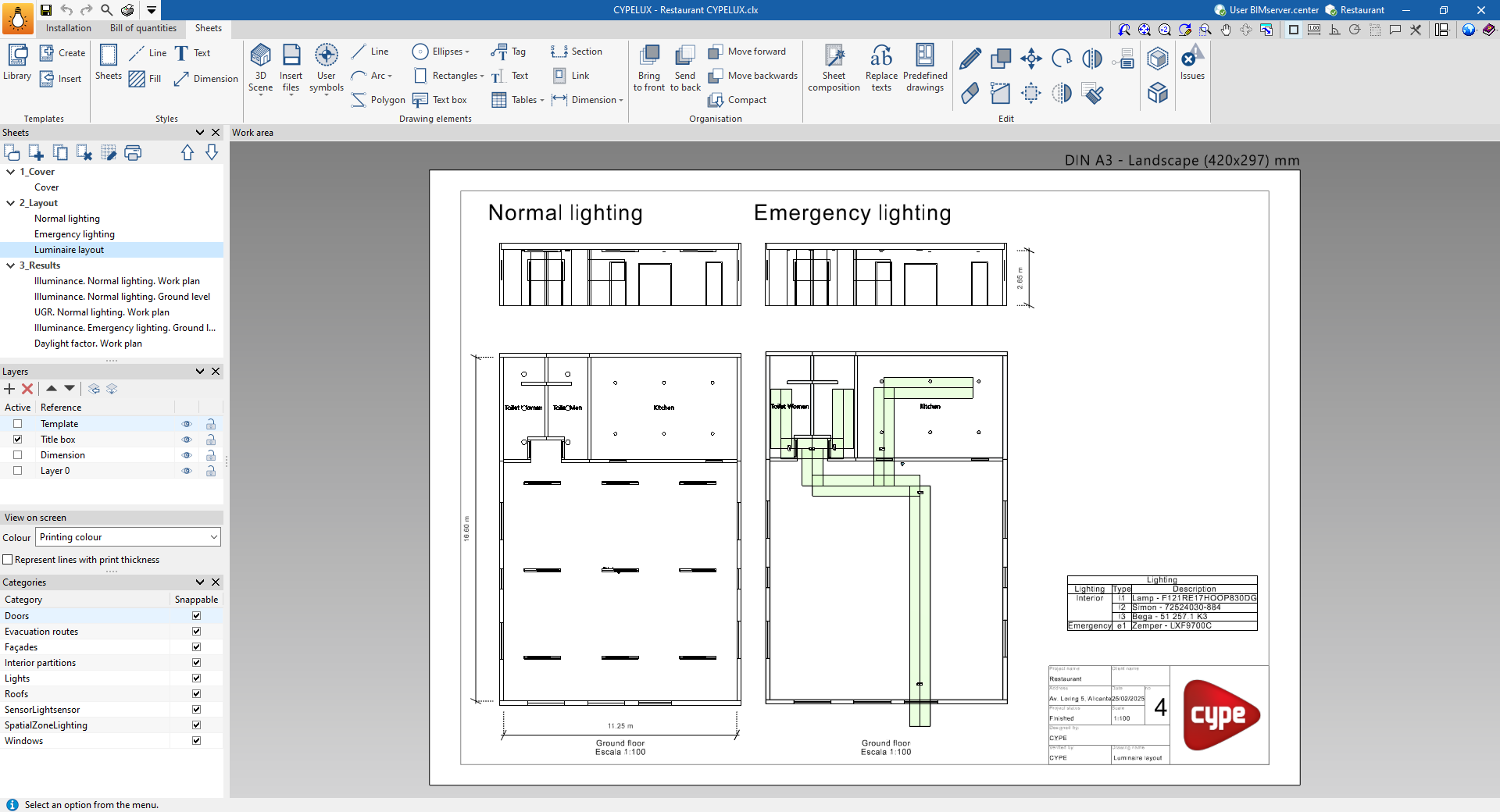
"Sheets" tab
Lastly, the "Sheets" tab can create and manage the drawings of the lighting installation, and displays the following:
- A top toolbar with different features, such as creating and managing templates, editing styles, and entering, editing or ordering drawing elements, among other options.
- The main work area, on the right-hand side of the screen, which displays the composition of each of the sheets.
- On the left-hand side are the main tools for managing the sheets and layers of the project, as well as the on-screen display options and the management of snaps by category.
Examples of lighting installation models
An example of a lighting installation that can be developed in the program is shown below, indicating the layout of the elements and the options that allow them to be entered into the model:
Lighting installation for a tertiary building
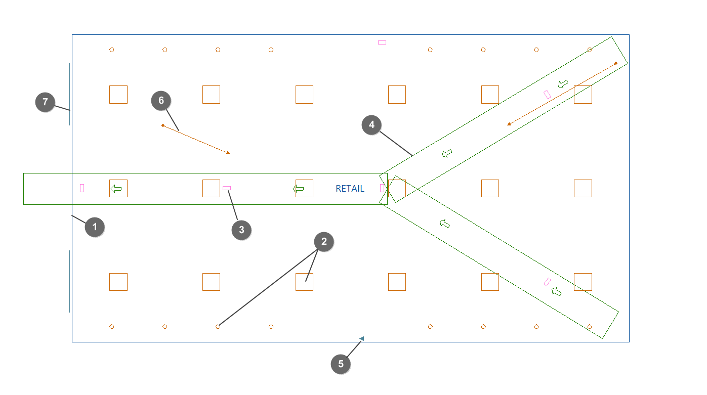
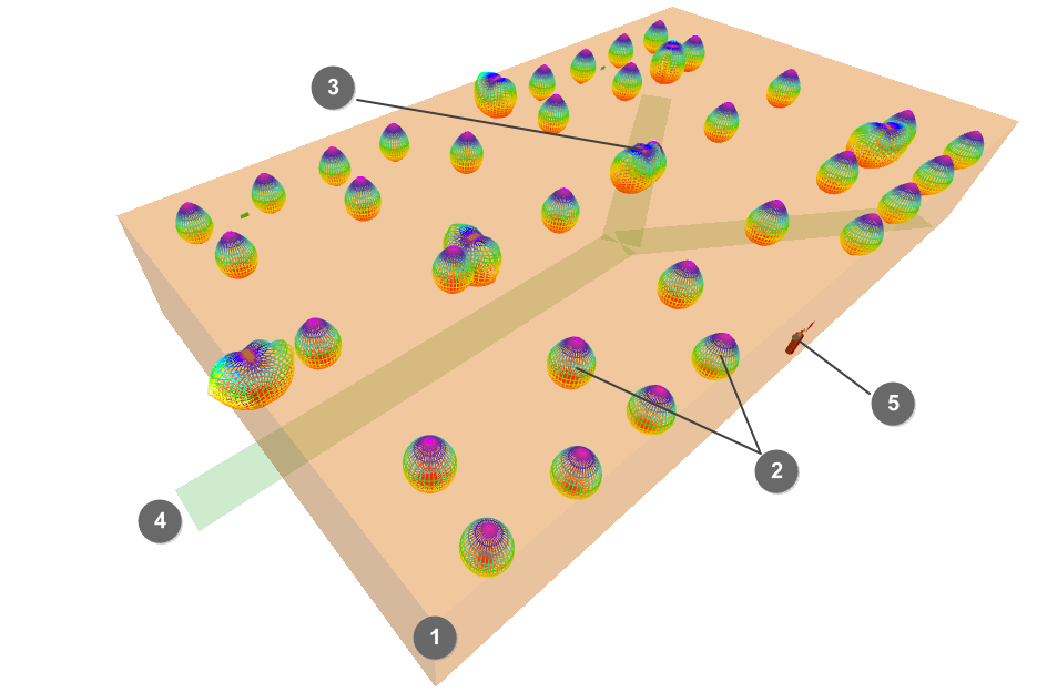
- Zone (imported from the BIM model or entered from "Lighting", "‘Zone").
- Indoor lighting (from "Lighting", "Indoor lighting").
- Emergency lighting (from "Lighting", "Emergency lighting").
- Escape routes (from "Safety/Protection", "Evacuation routes").
- Safety and/or protective equipment (from "Safety/Protection", "Equipment").
- Scene rendering views (from "Visualisation", "New view").
- Glazed openings (imported from the BIM model).
Creating a new job, linking to a project and importing data
When starting the program and clicking on "New", the program offers users the possibility to create a "New job", which can then be integrated into an existing project in BIMserver.center.
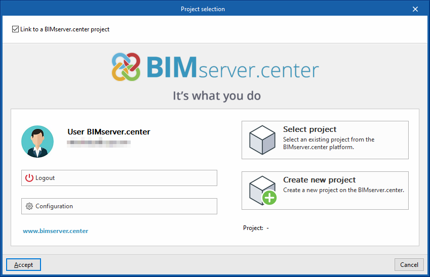
This is done in the "Project selection" window. On the left-hand side, you can log in with a BIMserver.center account.
- On the left-hand side, users can log in with a BIMserver.center account.
- On the right-hand side, the "Select project" option is used to choose an existing project. There is also the possibility to "Create a new project". In this case, the created project will be visible from BIMserver.centre from that moment on.
- The project can also be starting without being linked to the BIMserver.center platform. To do this, simply uncheck the box at the top left, "Link to a BIMserver.center project".
Once the new job has been created, the program interface is accessed, where the graphic window showing the model or models that have been imported stands out. At any time during the project, files can be shared or imported via the "BIMserver.center" group on the top right-hand side.
Importing BIM models
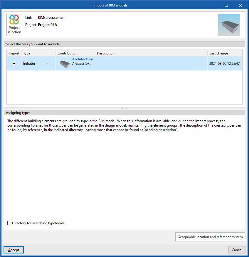
When creating a new job and selecting a project hosted on the BIMserver.center platform from "Select project", the "Import BIM models" window appears, which shows the files contained in that project in IFC format.
The program can include one or more of the existing models in the project. To do this, check the "Import" box and accept it. Users must decide whether the "Type" of each file is "Initiator" or "Additional".
The 3D view of the program will then display the imported models, both from the initiator and additional files. The program can also import the geometry of floors and spaces from the file marked as an initiator using a configuration wizard.
Configuration wizard: selecting standards, downloading catalogues and classifying spaces
Then, from the "Import BIM Models" window, the program opens the "Configuration" wizard, which consists of the following steps:
- In the first step, a list of the floor plans found in the BIM model is displayed. The floor plans to be imported can be selected here. The spaces included in a floor plan that has not been selected will not be imported.
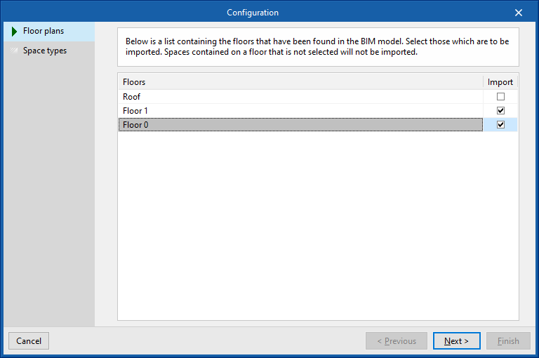
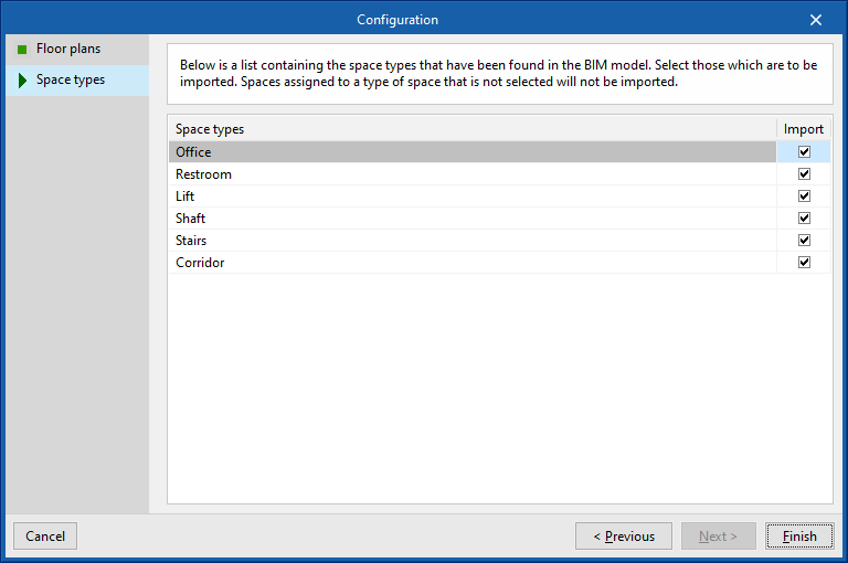
- The next step shows a list of the space types found in the BIM model. Here it is possible to select the space types to be imported. Spaces assigned to an unselected space type will not be imported.
To enter the zones manually, use the "Zone" option in the "Lighting" group of the main toolbar.
- Additionally, the glazed opening types will be imported automatically, and can be reviewed using the "Edit" option in the "Edit" group of the main toolbar on the imported glazed openings entered in the model.
Import results
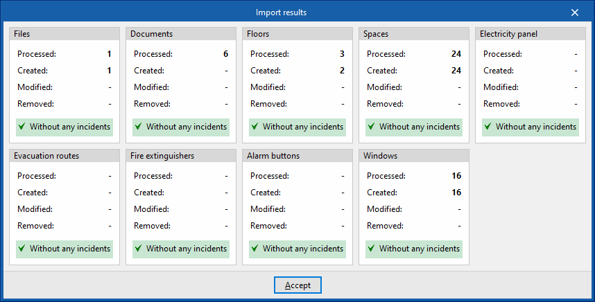
Finally, in the last step, an "Import results" box is displayed with the information of the processed, created, modified or deleted BIM model elements, including those listed in the table on the right.
General parameter configuration
In the "Project" group of the main toolbar on the "Installation" tab, you will find the option to configure the "General parameters" of the project:

General parameters
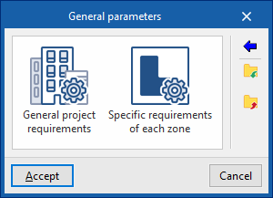
The available options are as follows:
- General project requirements
- Specific requirements of each zone
Importing code requirements
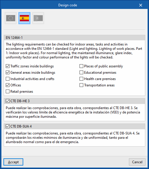
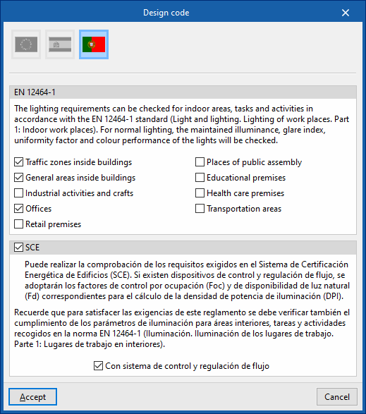
The wizard on the right-hand side of the "General Parameters" window allows you to import requirements from various national and international standards, such as the following:
 Europe
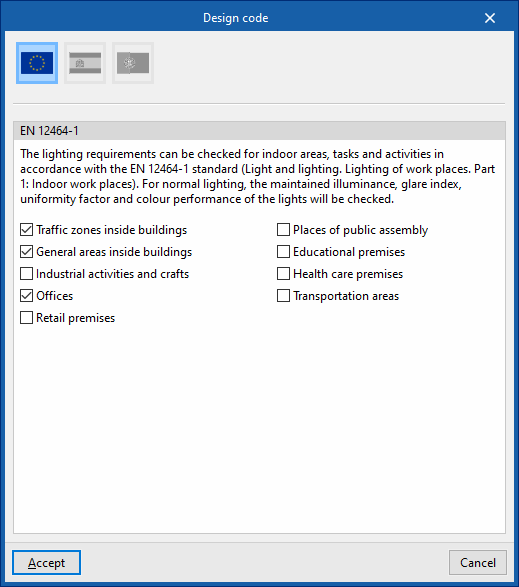
- EN 12464-1
Imports the lighting requirements specified by standard EN 12464-1 ("Light and lighting. Lighting of workplaces. Part 1: Indoor workplaces") for selected indoor areas, tasks and activities.
- EN 12464-1
 Singapur
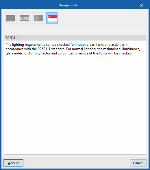
- SS 531-1
Imports the lighting requirements specified by standard SS 531-1.
- SS 531-1
 Europe
For installations in the rest of the world or to perform specific calculations, checks can be entered and configured manually in a customised manner.
| Note: |
|---|
| If necessary, zone checks can be modified after being imported. If requirements are imported again, the program will not undo these changes if the reference to the zone checks remains unchanged. If the reference has been modified, the program will re-import the corresponding zone check in a different entry. |
| Note: |
|---|
| The codes implemented in CYPE programs can be consulted at the following link. |
Import/export to files on disk
The remaining options in the right-hand column of the "General Parameters" window allow you to import and export the general parameter settings to files on disk.
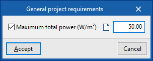
General project requirements
Allows you to configure the check value for the following general project parameter:
- Power
- Maximum total power
Specific requirements of each zone
Allows you to configure the checks to be performed on each type of zone. Subsequently, in the "Zone types" library accessible from the "Project" group or from the inserting or editing panel of each "Zone", these checks can be assigned to the desired zone type.
The program shows with marks in the right-hand column whether the checks are being applied.
When creating or editing each entry in the table, the "Zone check" window opens with the following options:
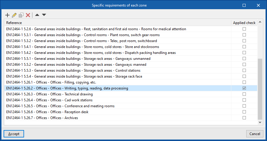
- Reference
Zone check reference.
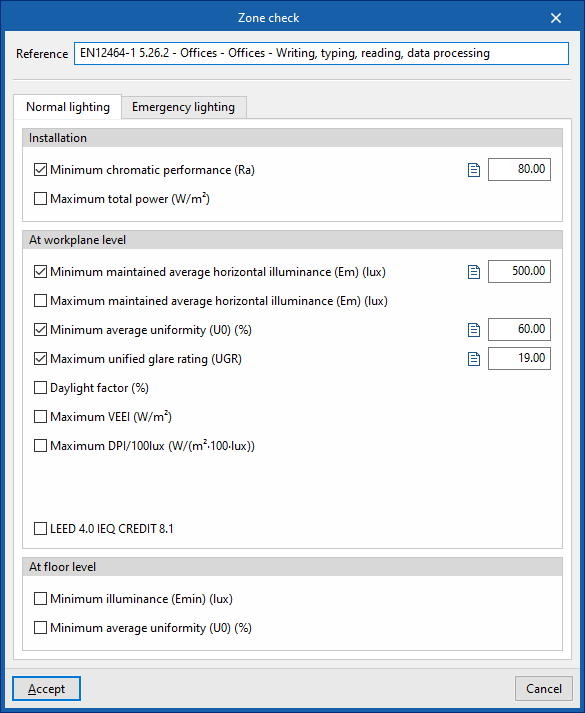
- "Normal lighting" tab
Activates and defines the check values for the following parameters, corresponding to the calculation of normal lighting. In addition, it is possible to add a descriptive text for each check:- Installation
- Minimum chromatic performance (Ra) (optional)
- Maximum total power (optional)
- At workplane level
- Minimum maintained average horizontal average illuminance (Em) (optional)
- Maximum maintained average horizontal illuminance (Em) (optional)
- Minimum average uniformity (U0) (optional)
- Maximum unified glare rating (UGR) (optional)
- Daylight factor (optional)
- Maximum VEEI (optional)
- Maximum DPI/100 lux (optional)
- Occupation dependency factor, FO
- Natural light dependency factor, FD
- LEED 4.0 CAI CREDIT 8.1 (optional)
Verifies compliance with the requirements necessary to obtain LEED 4.0 CAI CREDIT 8.1 (Option 2. Simulation: Illuminance Calculations) certification in this area. To do so, the illuminance levels produced by the effect of natural light inside the premises will be analysed. - At floor level
- Minimum illuminance (Emín) (optional)
- Minimum average uniformity (U0) (optional)
- Installation
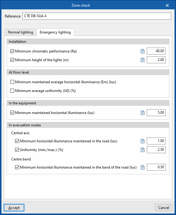
- "Emergency lighting" tab
Allows you to activate and define the check values for the following parameters, corresponding to the calculation of emergency lighting. In addition, it is possible to add a descriptive text for each check:- Installation
- Minimum chromatic performance (Ra) (optional)
- Minimum height of the lights (optional)
- At floor level
- Minimum maintained average horizontal illuminance (Em) (optional)
- Minimum average uniformity (U0) (optional)
- In the equipment
- Minimum maintained horizontal illuminance (Em) (optional)
- In evacuation routes
- Central axis
- Minimum horizontal illuminance maintained in the road (optional)
- Uniformity (min./max.) (optional)
- Centre band
- Minimum horizontal illuminance maintained in the band of the road (optional)
- Central axis
- Installation
Definition of parameters related to daylight calculation
In the "Lighting" group of the main toolbar, there is the "Daylight" option, which is used to define the parameters related to the calculation of daylight in the model:

Daylight supports the installation of normal artificial lighting to meet the lighting requirements of the zones. In addition, some regulations require minimum daylight quotient values, which can be set in the zone checks in the "General parameters".
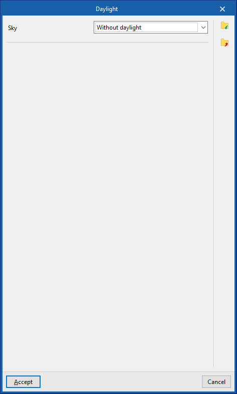
Daylight
Describes the sky in the scene and defines the parameters related to the daylight calculation, such as the sky type based on the CIE standard, the location of the building and its orientation.
Users must indicate whether they wish to carry out the daylight calculation and, if so, the properties defining the light source of the sky. The sky can be specified based on the date, time and location of the job or by altitude and azimuth. For this purpose, one of the following options can be selected in the "Sky" drop-down menu:
- Without daylight
- Only calculate the daylight factor
- Definition by date, time and location
- Definition by altitude and azimuth
The above options are listed below:
The program can import the types, geometry and layout of the glazed openings read from the BIM model, so it is only necessary to edit each type of glazed opening and define its characteristics.
Without daylight
If this option is selected, the program will not calculate the daylight.
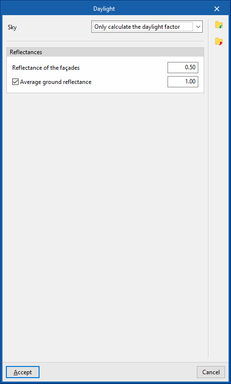
Only calculate the daylight factor
The program will calculate the daylight factor, without including the effect of daylight in the results. The daylight factor expresses the ratio between the illuminance at an indoor point produced by the effect of daylight and the illuminance that would be obtained if there were no obstructions. To calculate it, the program uses a reference CIE cloudy sky that produces a horizontal diffuse illuminance of 10000 lux.
- Reflectance of the façades
Indicates the reflectance value to be used for the external surfaces of the elements in the job. - Average ground reflectance (optional)
By activating this option, the average reflectance value of the ground can be indicated.
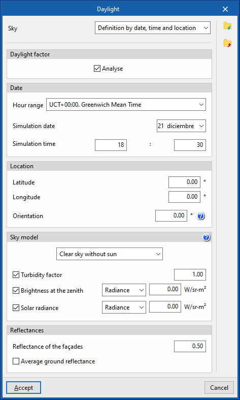
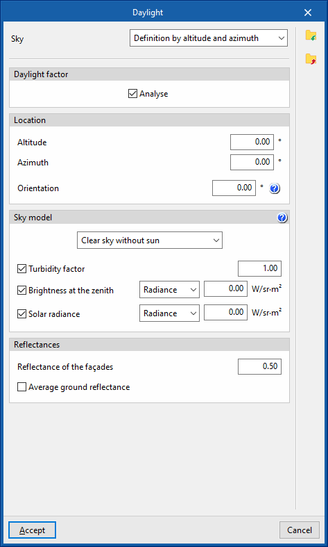
Definition by date, time and location / Definition by altitude and azimuth
In these cases, the following features can be edited in the configuration panel:
- Daylight factor
- Analyse (optional)
When this option is activated, the daylight factor will be calculated, without including the effect of daylight in the results. The daylight factor expresses the ratio between the illuminance at an indoor point produced by the effect of daylight and the illuminance that would be obtained if there were no obstructions. To calculate it, the program uses a reference CIE cloudy sky that produces a horizontal diffuse illuminance of 10000 lux.
- Analyse (optional)
- Date (just in "Definition by date, time and location")
The time zone, the date of the simulation and the time of the simulation are used together with latitude and longitude to determine the solar angles:- Hour range
- Simulation date
- Simulation time
- Location
- Latitude (just in "Definition by date, time and location")
Angular distance from the job location to the equator’s parallel line. - Longitude (just in "Definition by date, time and location")
Distancia angular desde la ubicación de la obra hasta el meridiano de Greenwich. - Altitude (just in "Definition by altitude and azimuth")
Angle formed between the sun and the horizontal line of the scene. - Azimuth (just in "Definition by altitude and azimuth")
Angle formed between the sun and the southern direction of the scene. - Orientation
The orientation of the building is essential when a daylight calculation is carried out and a sunny sky type is assigned. In these cases, in contrast to cloudy skies, the illumination distribution is not symmetrical around the zenith. The angle describing the orientation corresponds to the offset between the direction of the Y-axis of the scene and north, in a counter-clockwise direction.
Thanks to the linking of the job with a BIM model, if the orientation is already specified in an IFC file, this parameter will appear directly with the corresponding value.
- Latitude (just in "Definition by date, time and location")
- Sky model
- Sky model selection
The type of sky model to be used in the daylight simulation can be selected from the following:- Clear sky without sun
Corresponds to the CIE clear sky standard without considering direct sunlight illumination. - Clear sky with sun
Corresponds to the CIE clear sky standard including direct sunlight illumination. - Partially overcast sky without sun
Corresponds to the CIE medium sky standard whose lighting conditions are between those of clear sky and cloudy sky. In this case, direct sunlight illumination is not considered. - Partially overcast sky with sun
Corresponds to the CIE medium sky standard including direct sunlight illumination. - Overcast sky
Corresponds to the CIE cloudy sky standard. The sky brightness increases progressively with altitude from the horizon towards the zenith, but does not vary with respect to azimuth. This sky type is commonly used to determine daylight factors. - Uniformly overcast sky
Represents a sky with completely uniform lighting.
- Clear sky without sun
- Turbidity factor (optional)
By activating this option, the turbidity factor can be defined. The higher the turbidity factor, the greater the atmospheric dispersion. A value equal to 1 indicates an ideal clear atmosphere while values below 1 are physically impossible. - Brightness at the zenith (optional)
Activating this option allows the zenith brightness to be defined. If not directly specified, the zenith radiance is determined from the solar angle and the sky turbidity. The zenith brightness can also be calculated from the horizontal diffuse irradiance. To do so, the corresponding magnitude is selected from the following drop-down menu:- Radiance / Irradiance
- Solar radiance (optional)
By activating this option, solar radiance can be defined. If not specified directly, it is determined from the solar altitude. If a value of 0 is specified, no sun modelling will take place. The solar radiance can also be calculated from the direct horizontal irradiance. To do this, the corresponding magnitude is selected in the following drop-down menu:- Radiance / Irradiance
- Sky model selection
- Reflectances
- Reflectance of the façades
Indicates the reflectance value to be used for the external surfaces of the elements in the job. - Above ground reflectance (optional)
By activating this option, the average reflectance value of the ground can be indicated.
- Reflectance of the façades
Automatic lighting distribution
In the "Lighting" group of the main toolbar, there are options for automatically arranging sets of lights in the model using different distribution types:

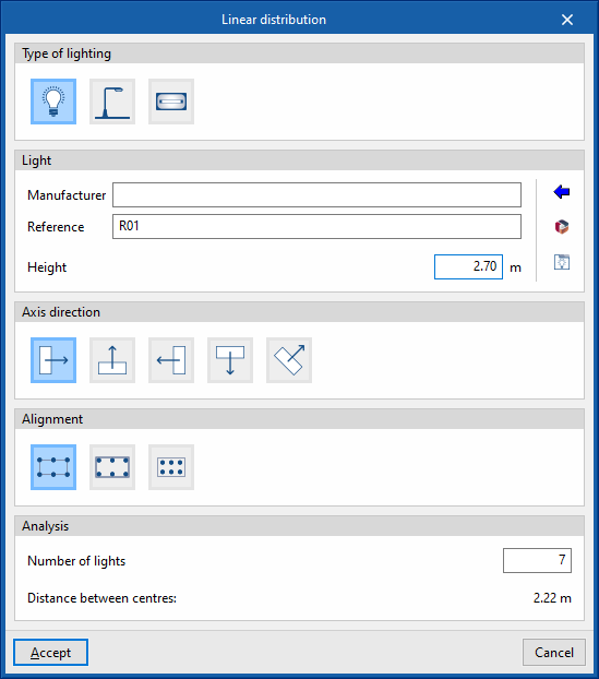
Linear distribution
Enters a linear distribution of lighting.
To do this, two points are marked in the work area by defining a reference line. When you do this, the program displays the following window for defining the parameters of the distribution:
- Type of lighting
- Internal
- External
- Emergency
- Lighting
- Manufacturer / Reference
Manufacturer and model reference of the lighting in the distribution. Using the "Selection of a light from the library" wizard, available on the right, the program allows the selection of luminaires from the "Generic element library" or from "Manufacturer catalogues". These types of elements can be created and edited from the "Catalogues"/"Catalogue management" and "Internal lighting types", "External lighting types" or "Emergency lighting types" options, respectively, available within the "Project" group of the main toolbar of the general interface or to the right of the lighting layout input panel itself. - Height
Height of the lighting with respect to the ground level.
- Manufacturer / Reference
- Local axes direction
Defines the lighting orientation. For this purpose, users indicate whether the horizontal plane of origin of the photometric curve of the lighting is aligned or oriented at a certain angle to the reference line.- Aligned
- Oriented 90º
- Oriented 180º
- Oriented 270º
- With user-defined orientation
- Alignment
Adjusts the layout of the lighting with respect to the reference line entered in the model.- Centre-centre
The reference line marks the separation between the centres of the lighting at the ends. - External edges
The reference line marks the spacing between the outer edges of the lighting at the ends. - Symmetrical
The lights are laid out symmetrically on the reference line, maintaining a spacing from the ends of the line equal to half the spacing between lights.
- Centre-centre
- Analysis
- Number of lights
Number of lights in the linear distribution. - Space between centres
Displays the spacing between lighting centres. This is a value calculated according to the other data entered in this window.
- Number of lights
After accepting, the program generates and positions the lighting according to the defined configuration. If necessary, the position or properties of the lighting can be edited individually at a later stage.

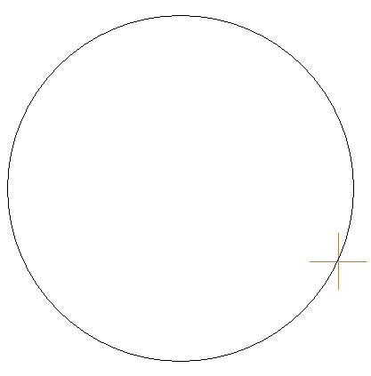
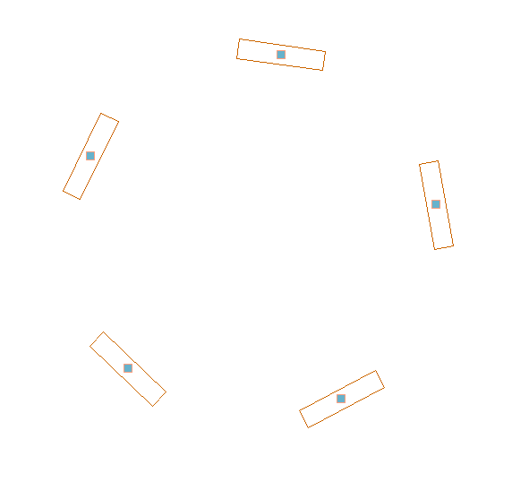
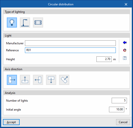
Circular distribution
Enters a circular distribution of lighting.
To do this, two points are marked in the work area by defining a reference circle. When you do this, the program displays the following window for defining the parameters of the distribution:
- Type of lighting
- Internal
- External
- Emergency
- Lighting
- Manufacturer / Reference
Manufacturer and model reference of the lighting in the distribution. Using the "Selection of a light from the library" wizard, available on the right, the program allows the selection of luminaires from the "Generic element library" or from "Manufacturer catalogues". These types of elements can be created and edited from the "Catalogues"/"Catalogue management" and "Internal lighting types", "External lighting types" or "Emergency lighting types" options, respectively, available within the "Project" group of the main toolbar of the general interface or to the right of the lighting layout input panel itself. - Height
Height of the lighting with respect to the ground level.
- Manufacturer / Reference
- Local axes direction
Defines the lighting orientation. For this purpose, users indicate whether the horizontal plane of origin of the photometric curve:- Oriented to the outside of the circumference
- Is tangent to the circumference, counterclockwise
- Oriented to the inside of the circumference
- Is tangent to the circumference, clockwise
- Has a user-defined orientation
- Analysis
- Number of lights
Number of lights in the circular distribution. - Initial angle
Angle of position of the first light in the distribution on the reference circle, measured in a clockwise direction
- Number of lights
After accepting, the program generates and positions the lighting according to the defined configuration. If necessary, the position or properties of the lighting can be edited individually at a later stage.
Rendering scenes
In the "Visualisation" group of the program's main toolbar, there are options for generating and visualising the rendering of scenes:

Thanks to the inclusion of the Radiance analysis engine in the program, these options can be used to represent the effect of lighting produced by the installation of normal or emergency lighting on a space, as well as the effect of natural lighting, creating scene views on the model and generating rendered images of these scenes.
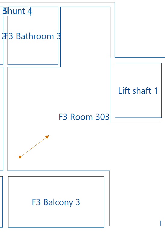
New view
Enters a new view in the model by marking the points that define its position and direction on the plan.
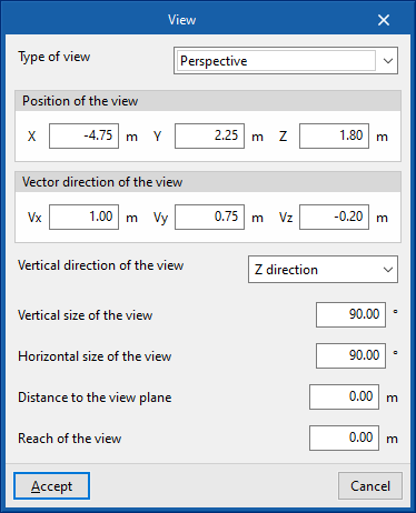
In doing so, the following features are configured:
- Type of view
- Perspective
- Cylindrical
- Hemispheric fisheye
- Angular fisheye
- Ojo de pez planisférica
- Position of the view
Absolute coordinates of the point defining the direction of the view. The program takes these data from the points marked on the plan, but they can be modified:- X, Y, Z
- Vector direction of the view
Components of the vector defining the direction of the view. The program takes these data from the points marked on the plan, but they can be modified:- Vx, Vy, Vz
- Vertical direction of the view
- X direction
- Y direction
- Z direction
- Vertical size of the view
- Horizontal size of the view
- Distance to the view plane
- Reach of the view
These views are represented in the workspace by the symbols of a point and a vector.
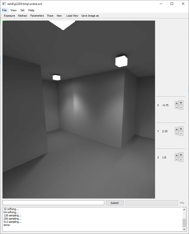
Render
Selects a view previously inserted in the model and renders it.
The program will generate the scene with the Radiance analysis engine and display the rendering process and result in a specific window, in which the image is refined through several sweeps.
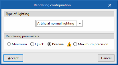
Rendering configuration
Configures the rendering of scenes.
When rendering, users can choose whether they want to display the scene with normal artificial lighting (interior and exterior), emergency lighting or natural lighting with daylight, as well as the degree of accuracy of the scene.
- Artificial normal lighting / Emergency lighting / Natural lighting
- Rendering parameters (Minimum / Quick / Precise / Maximum precision)
Integration into the BIMserver.center platform
Many of CYPE's programs are connected to the BIMserver.center platform and allow collaborative work to be carried out via the exchange of files in formats based on open standards.
Please note that, to work on BIMserver.center, users can register on the platform free of charge and create a profile.
When accessing a program connected to the platform, the program connects to a project in BIMserver.center. This way, the files of the projects that have been developed collaboratively in BIMserver.center are kept up to date.

| More information: |
|---|
| For further details related to using CYPE software via the BIMserver.center platform, please click on this link. |


