Introduction
The "Digital Model" tab in CYPEPLUMBING can be used to design a detailed digital model or detailing of water supply, drainage and solar thermal energy systems using different solutions from different manufacturers.
The parts that make up the pipes and fittings (such as elbows, tees, branches or reducers) can be generated automatically from the systems designed in the program or chosen manually by the user.
As a result, reports and files are generated with quantities of the materials and products used, as well as the possibility of obtaining detailed plans of the system.
"Digital Model" tab workspace
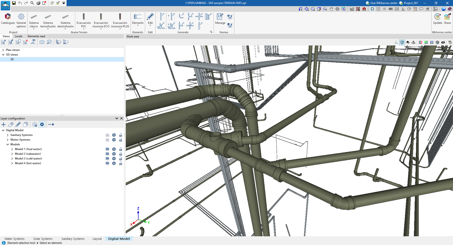
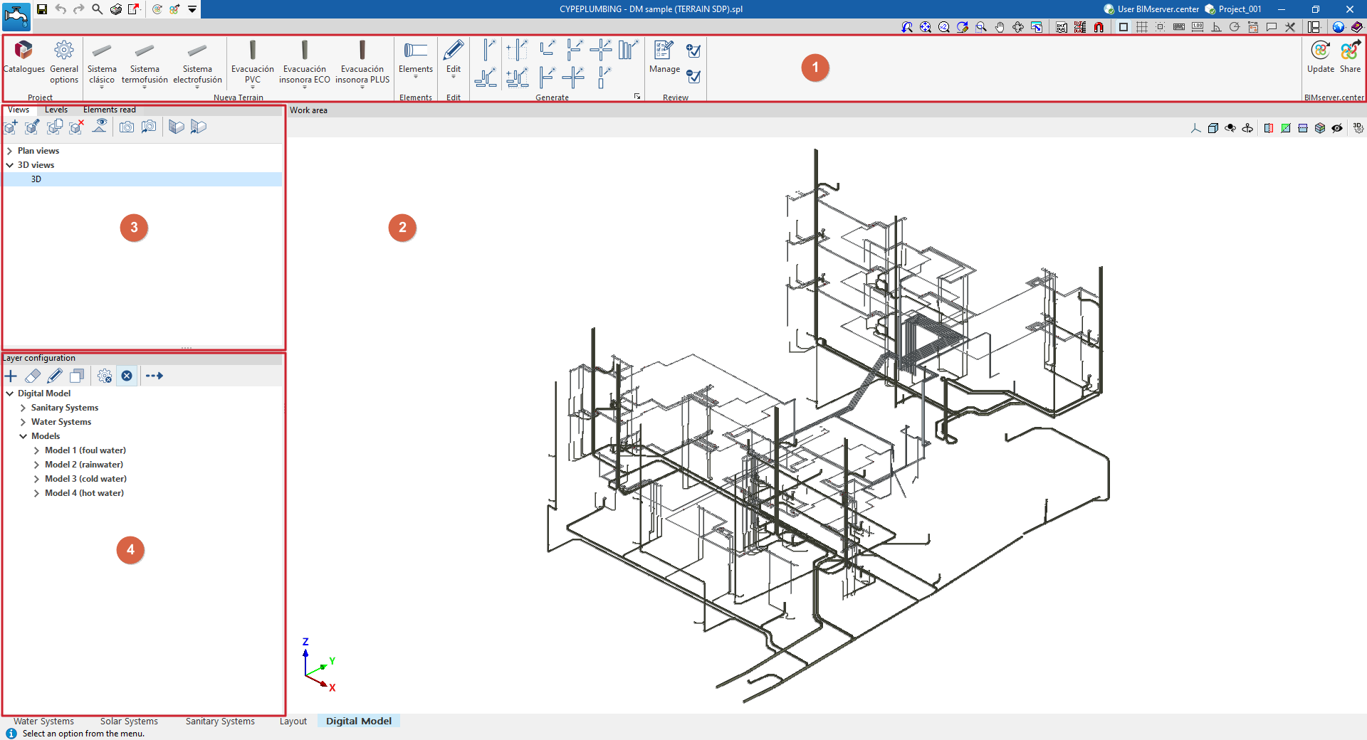
The "Digital Model" tab provides a work environment that can be used to design detailed models or detail drawings of water supply, drainage and solar thermal energy systems, both in 3D view and in any type of 2D view (such as floor plans and elevations). This allows you to enter or edit the elements of the detailed model using the most appropriate view at any given time.
This tab shows:
- A top toolbar (1) containing the tools for downloading catalogues and configuring the general project options; entering, editing and/or automatically generating the elements that make up the detailed model; and managing the model review.
- The workspace (2), on the right-hand side of the screen, where the elements of the detailed model are entered, edited and displayed.
- At the top of the left-hand side (3), several panels with tools for defining the views and levels of the project, and managing the visibility of the elements read.
- At the bottom of the left-hand side (4), a panel for configuring the layers of the detailed model and the checks to be carried out on it, as well as for performing these checks.
Work sequence for creating a detailed model of plumbing systems
The sequence of operations for generating and managing the detailed digital model of the system in the program is as follows.
- Export the plumbing and sanitation installations already calculated in the programme to the "Digital Model" tab (using the "Digital Model" option in the "Analysis" group in each corresponding tab, "Water Systems", "Sanitary Systems" and/or "Solar Systems").
- Access the "Digital Model" tab, review the imported installations and initial configuration:
- View the exported installations in the "Digital Model" tab (from "Layer configuration").
- Import manufacturer catalogues for the detailed model (from the "Catalogues" option in the "Project" group).
- Configuration of the series of materials to be used in the project (from the "General options" option in the "Project" group).
- Creation of the detailed model. Detailed models for each installation can be generated automatically or created manually, piece by piece:
- Automatic generation of detailed models:
- First, the pieces that make up the pipes for each detailed model are generated ("Pipes" option in the "Generate" group). The first time this option is run, a detailed model will be added to the list of models accessible from "Layer configuration".
- Next, the fittings are generated ("Fittings" option in the "Generate" group) for each detailed model generated.
- (Optional) For greater control and precision in the generation process, you can use the other options in the "Generate" group, which allow you to generate only selected parts of the installation or a specific type of fitting.
- (Optional) If you need to add more detailed models or edit any of the detailed models generated, use the specific options in the top toolbar of "Layer settings" ("Add", "Delete", "Edit", "Copy").
- (Optional) If necessary to complete the model at any point, you can enter and place the parts of each detailed model one by one from the options in the "Elements" group or from the options in the specific group for each manufacturer that appears when you download a manufacturer and restart the program.
- (Optional) If you need to modify any element of the detailed model, you can use the tools in the "Edit" group.
- Automatic generation of detailed models:
- Checking and reviewing the detailed model
- Configure the checking options for each detailed model (from the "Checks" option in "Layer settings").
- Checking the detailed models (from the "Check errors" option in "Layer settings"). Any errors found during the check will be displayed on the screen.
- (Optional) You can track the work process using the detailed model review options (in the "Review" group), which allow the user to colour the parts of the model that are in different review states.
- (Optional) If the model requires it, it may be necessary to return to the analysis tabs, make modifications to the design, and re-export to the "Digital Model" tab. Then, in the "Digital Model" tab, the parts of the installation with changes can be deleted and regenerated.
- Obtaining and exporting results
- Obtaining the reports with the quantities of the pipe parts and fittings (from the "Reports" option in the top bar, in the "Digital Model" tab).
- Obtaining the drawings of the detailed model indicating the reference of the parts and fittings (using the options in the "Layout" tab).
- Obtaining the measurements of parts and fittings in BC3 format (from the "Export in BC3 format" option in the top bar, in the "Digital Model" tab).
- Exporting the detailed model to BIMserver.center (from the "Share" option in the "BIMserver.center" group).
Exporting plumbing systems to the "Digital Model" tab
"Digital Model" option
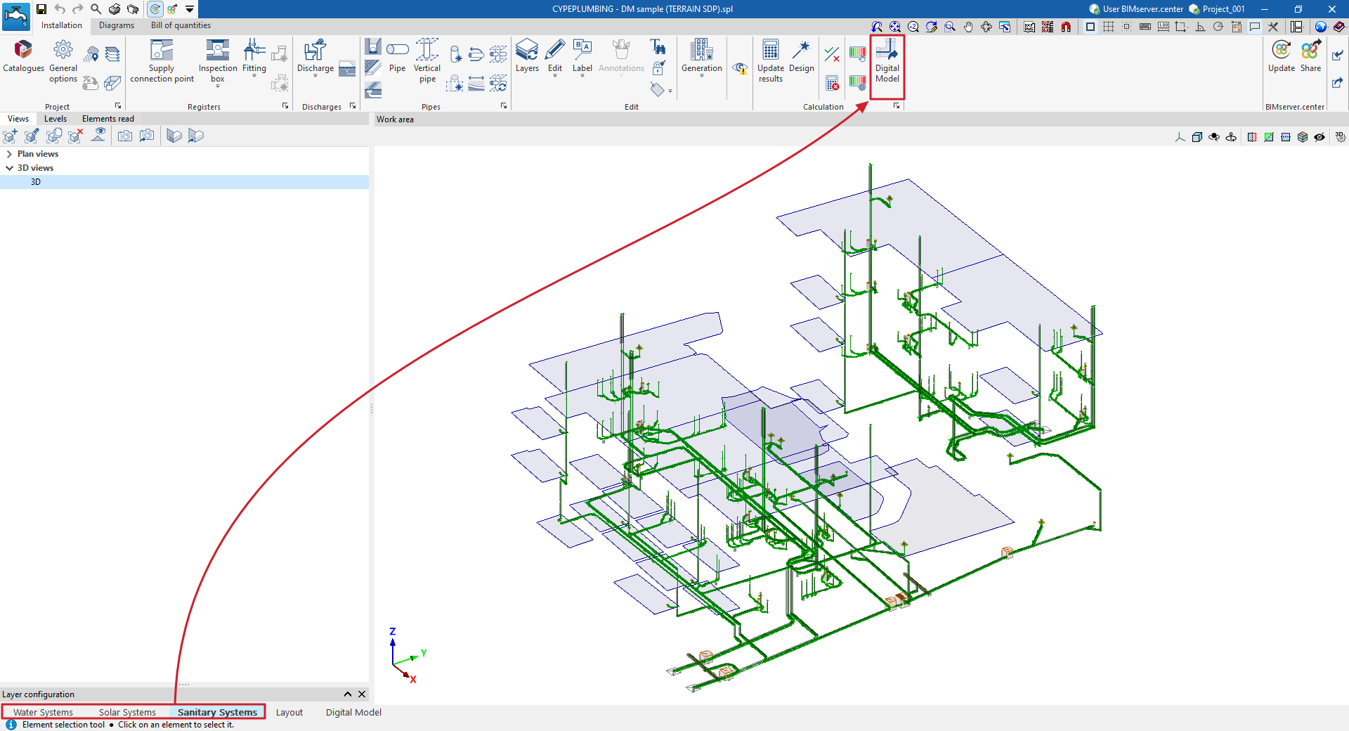
To create a detailed model or breakdown of the water supply, drainage or solar thermal energy systems, you need to export the information from the calculation model created in the "Water Systems", "Sanitary Systems" or "Solar Systems" tabs to the "Digital Mode" tab.
To do this, use the "Digital Model" option in the "Calculation" group of the top toolbar on the "Installation" tab.
| Note: |
|---|
| This action must be performed from each of the different tabs mentioned if you want to create a detailed model of the different systems. |
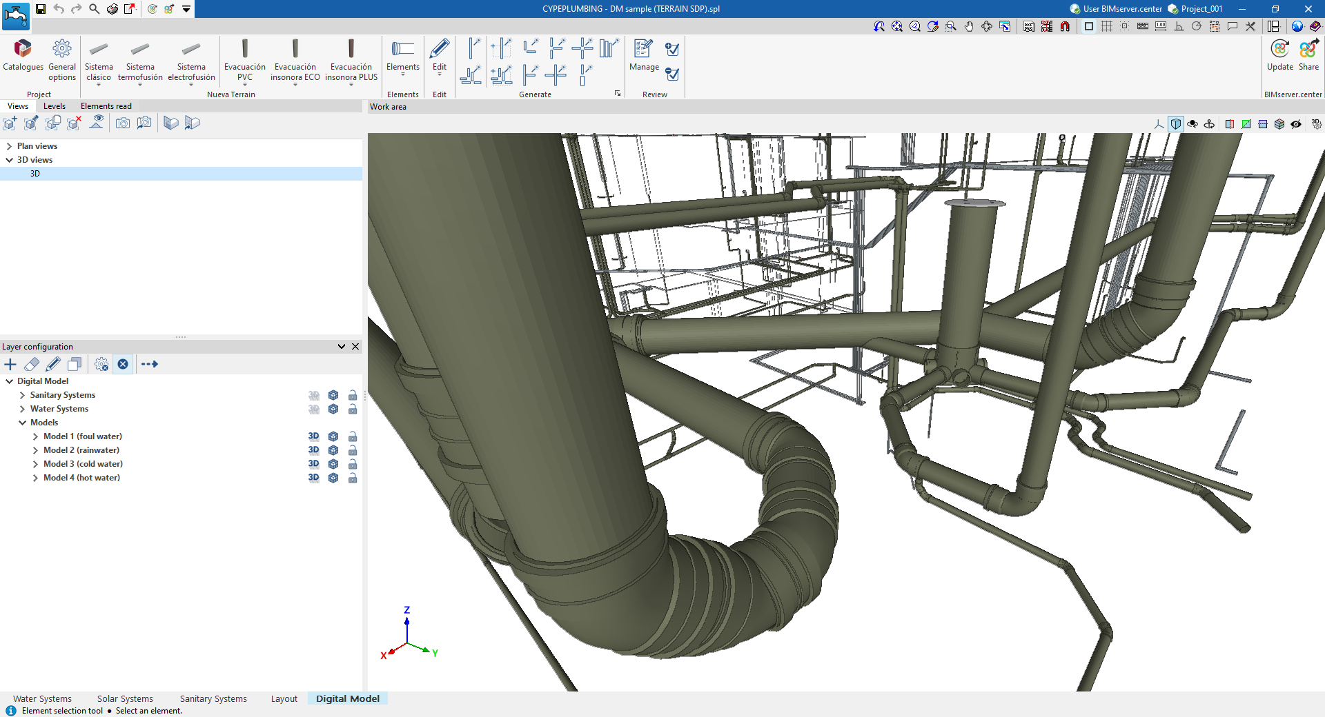
Detailed model layer configuration
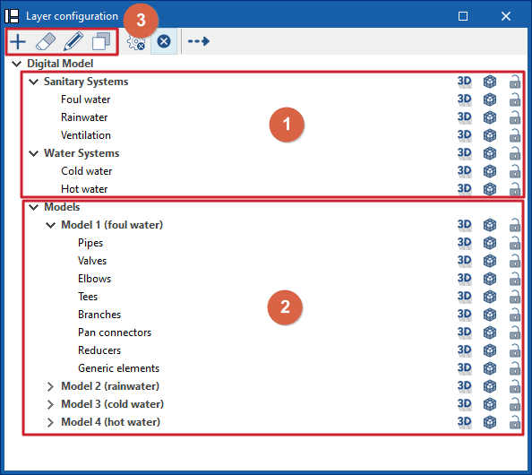
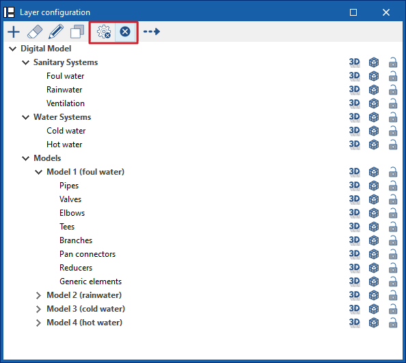
The "Layer Configuration" panel is located by default on the left side of the ‘Digital Model’ tab and offers the following controls.
Display of imported installations (1)
The display of the different installations exported from other tabs can be enabled or disabled using the options in the "Water Systems", "Sanitary Systems" and/or "Solar Systems" lines.
Display and editing of detailed models (2)
The display of the different detailed models generated with the options in the "Generate" group is managed from the lines in the "Models" section.
Editing detailed models (3)
In addition, the options in the top toolbar allow you to "Add", "Delete", "Edit" or "Copy" each of the detailed models generated.
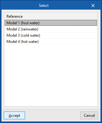
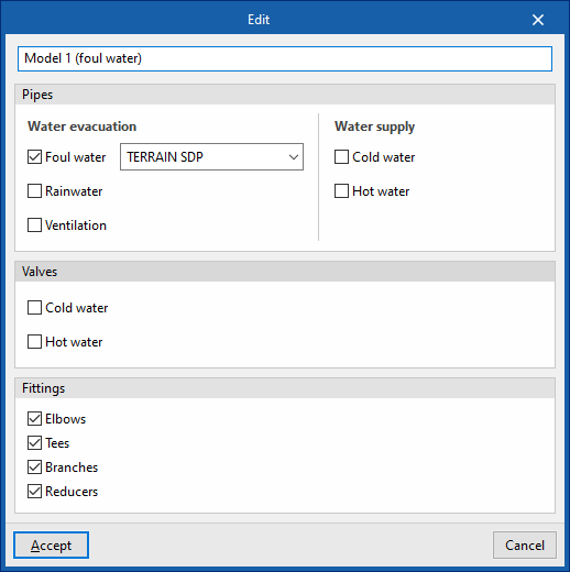
When you click on "Edit", you must choose one of the available detailed models. When you accept, the program opens a pop-up window where you can change its reference, reassign the series of materials to be used in each associated type of installation (in the "Pipes" section), and activate or deactivate the categories of fittings to be generated in the model (in the "Fittings" section).
Available options
The options on the right of this panel allow you to adjust the display and configure the capture of the elements in each category. They are as follows:
 Three-dimensional representation
Enables or disables the three-dimensional or volumetric representation of the elements in the category. Opacity
Adjusts the opacity of the 3D representation of the elements in the category. Capture
Enables or disables the capture of elements in the category.
On the other hand, the "Direction" option at the top of this panel shows the axis of the pipes together with the flow direction calculated in the "Water Systems", "Sanitary Systems" or "Solar Systems" tabs. It is necessary to adjust the opacity of the pipe layers to view it correctly.
Detailed model checks
The "Checks" button at the top of the "Layer settings" panel opens a window where the following checks can be enabled or disabled for each of the detailed models generated:
- Disconnected elements
- Connections pending solution
- Diameters of elements in contact
- Compatibility of the diameter with the system project
Allows the program to warn that the dimensions of the product in the detailed model do not match those in the design model. In this case, you must return to the corresponding analysis tab, make the necessary changes to check the actual situation, and use the "Digital Model" option again to re-export the information to this tab. - Slope less than 0.5%
- Tolerances for elements in contact
Tolerance value in degrees between parts in contact.
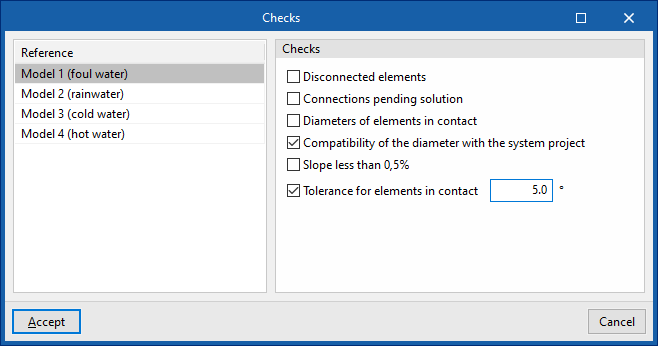
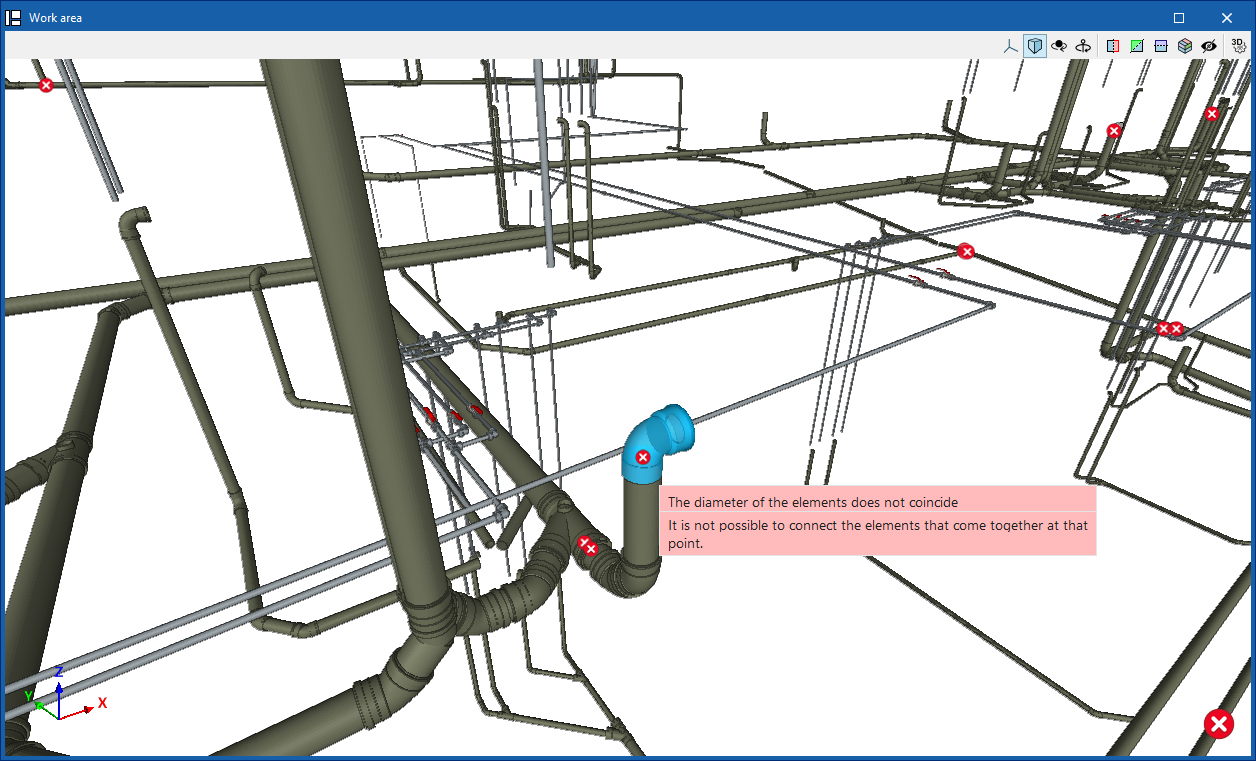
These checks are performed by clicking on the "Check errors" option, also at the top of the "Layer settings" panel.
Any errors found are displayed on the model elements in the "Workspace". Hovering the cursor over each error displays an informative text describing it.
Importing manufacturer catalogues for the detailed model of plumbing systems
In the "Digital Model" tab, manufacturer catalogues are loaded from the "Catalogues" option in the "Project" group at the top so that they are available for use in the detailed model.

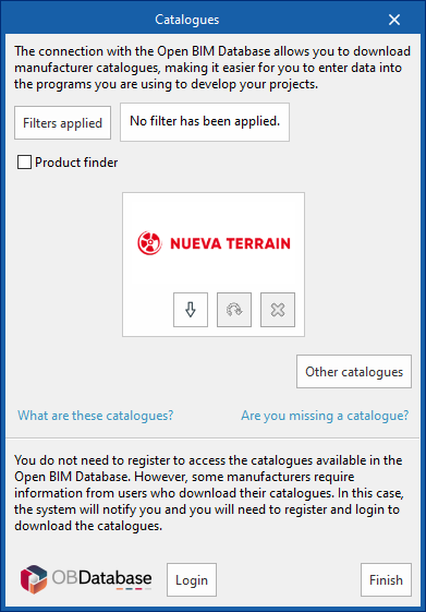
Catalogues
You can download manufacturer catalogues using the connection to the Open BIM Database, facilitating the entry of data into the program for project development.
Clicking on this option opens a window with the available manufacturer catalogues.
Using the "Applied filters" option, it is possible to apply filters by "Language" and "Country" to show only those manufacturers that offer product catalogues with these characteristics.
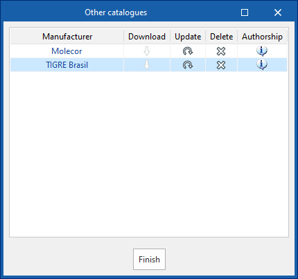
Downloading catalogues
The following options are shown for each manufacturer:
- Download
Downloads the manufacturer's catalogue. The products in the catalogue will be available in the project. - Update
Updates the selected manufacturer's catalogue to the latest version, deleting the downloaded version in the project. - Delete
Deletes the selected manufacturer's catalogue. The products in the catalogue will no longer be available in the project.
Connection to Open BIM Database
At the bottom of this dialogue box, the program allows the user to log in with their Open BIM Database account and password.