Introduction
The "Digital Model" tab in CYPEPLUMBING can be used to design a detailed digital model or detailing of water supply, drainage and solar thermal energy systems using different solutions from different manufacturers.
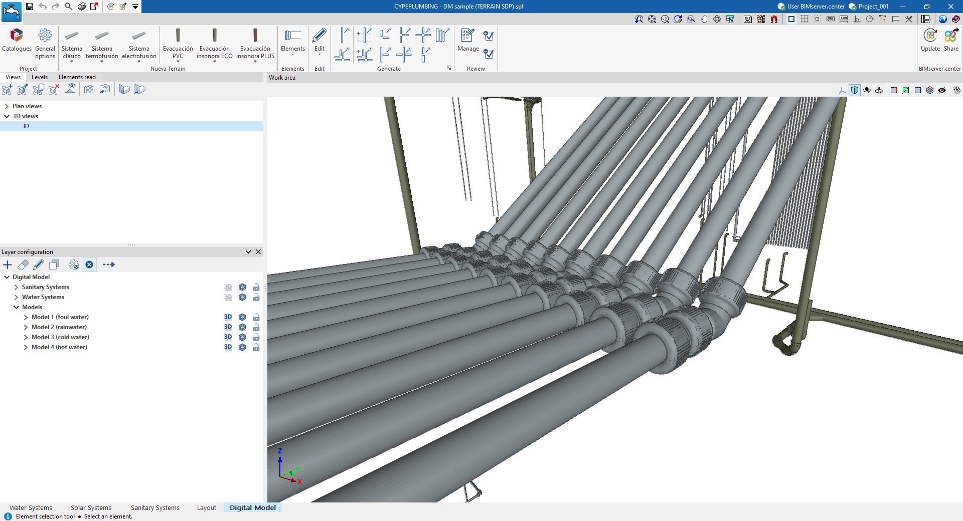
The parts that make up the pipes and fittings (such as elbows, tees, branches or reducers) can be generated automatically from the systems designed in the program or chosen manually by the user.
As a result, reports and files are generated with quantities of the materials and products used, as well as the possibility of obtaining detailed plans of the system.
"Digital Model" tab workspace
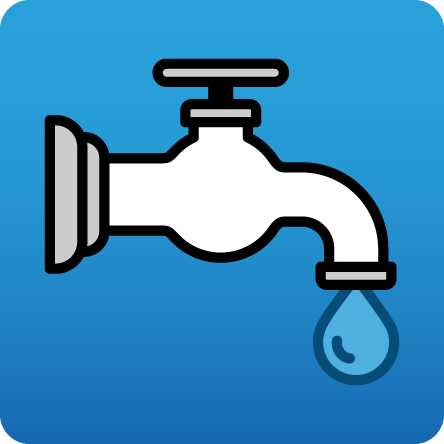
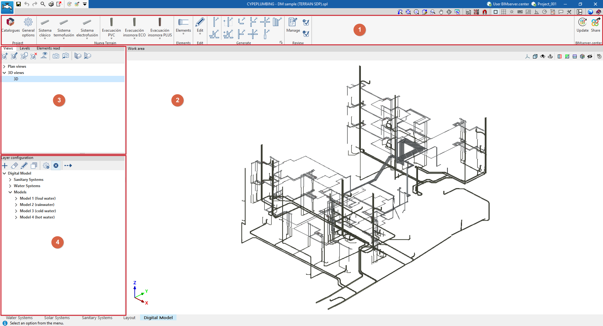
The "Digital Model" tab provides a work environment that can be used to design detailed models or detail drawings of water supply, drainage and solar thermal energy systems, both in 3D view and in any type of 2D view (such as floor plans and elevations). This allows you to enter or edit the elements of the detailed model using the most appropriate view at any given time.
This tab shows:
- A top toolbar (1) containing the tools for downloading catalogues and configuring the general project options; entering, editing and/or automatically generating the elements that make up the detailed model; and managing the model review.
- The workspace (2), on the right-hand side of the screen, where the elements of the detailed model are entered, edited and displayed.
- At the top of the left-hand side (3), several panels with tools for defining the views and levels of the project, and managing the visibility of the elements read.
- At the bottom of the left-hand side (4), a panel for configuring the layers of the detailed model and the checks to be carried out on it, as well as for performing these checks.
Work sequence for creating a detailed model of plumbing systems
The sequence of operations for generating and managing the detailed digital model of the system in the program is as follows.
- Export the plumbing and sanitation installations already calculated in the program to the "Digital Model" tab (using the "Digital Model" option in the "Analysis" group in each corresponding tab, "Water Systems", "Sanitary Systems" and/or "Solar Systems").
- Access the "Digital Model" tab, review the imported installations and initial configuration:
- View the exported installations in the "Digital Model" tab (from "Layer configuration").
- Import manufacturer catalogues for the detailed model (from the "Catalogues" option in the "Project" group).
- Configuration of the series of materials to be used in the project (from the "General options" option in the "Project" group).
- Creation of the detailed model. Detailed models for each installation can be generated automatically or created manually, piece by piece:
- Automatic generation of detailed models:
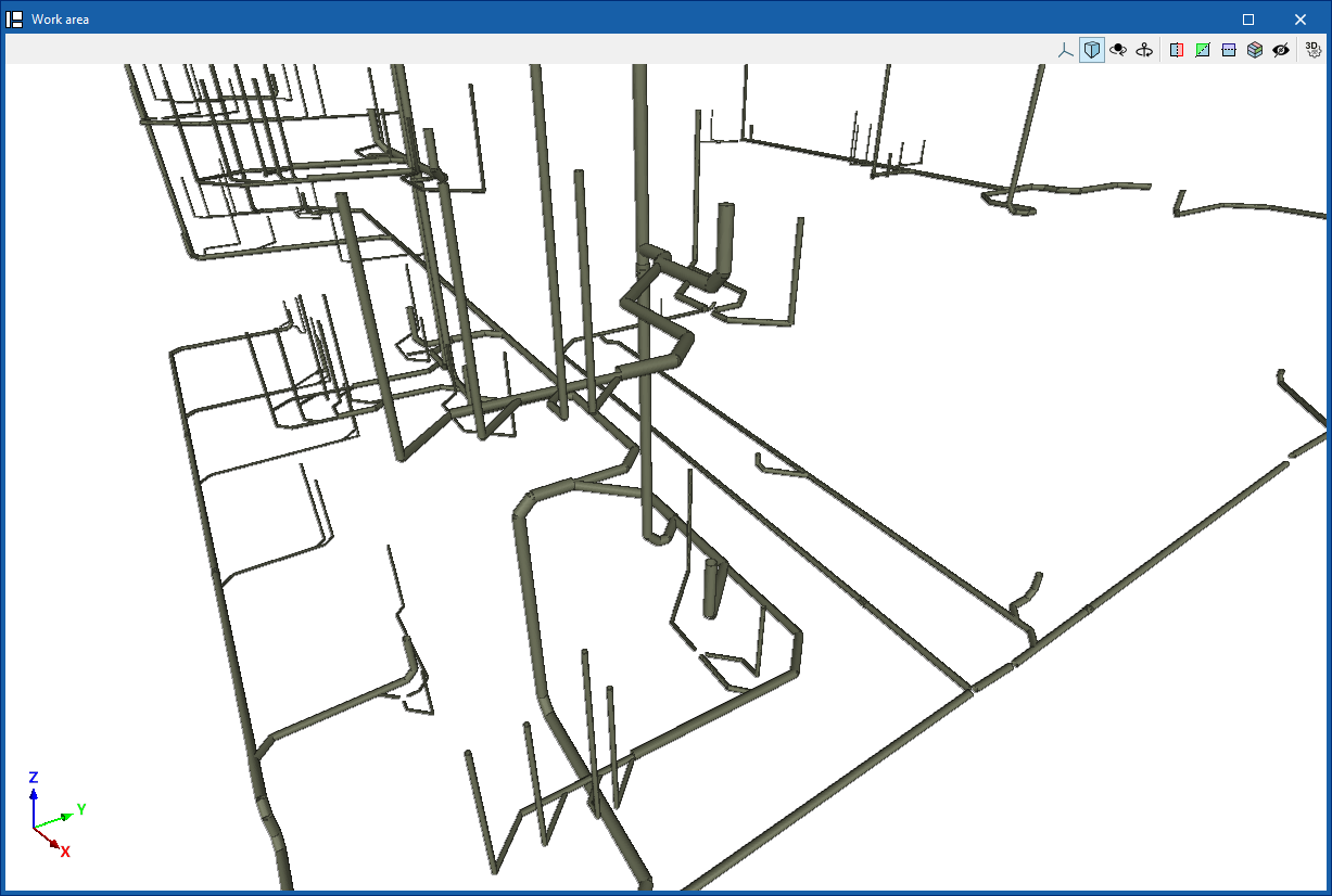
- First, the pieces that make up the pipes for each detailed model are generated ("Pipes" option in the "Generate" group). The first time this option is run, a detailed model will be added to the list of models accessible from "Layer configuration".
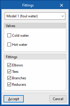
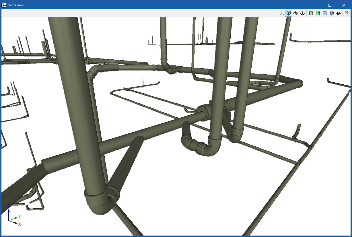
- Next, the fittings are generated ("Fittings" option in the "Generate" group) for each detailed model generated.
- (Optional) For greater control and precision in the generation process, you can use the other options in the "Generate" group, which allow you to generate only selected parts of the installation or a specific type of fitting.
- (Optional) If you need to add more detailed models or edit any of the detailed models generated, use the specific options in the top toolbar of "Layer settings" ("Add", "Delete", "Edit", "Copy").
- (Optional) If necessary to complete the model at any point, you can enter and place the parts of each detailed model one by one from the options in the "Elements" group or from the options in the specific group for each manufacturer that appears when you download a manufacturer and restart the program.
- (Optional) If you need to modify any element of the detailed model, you can use the tools in the "Edit" group.
- Automatic generation of detailed models:
- Checking and reviewing the detailed model
- Configure the checking options for each detailed model (from the "Checks" option in "Layer settings").
- Checking the detailed models (from the "Check errors" option in "Layer settings"). Any errors found during the check will be displayed on the screen.
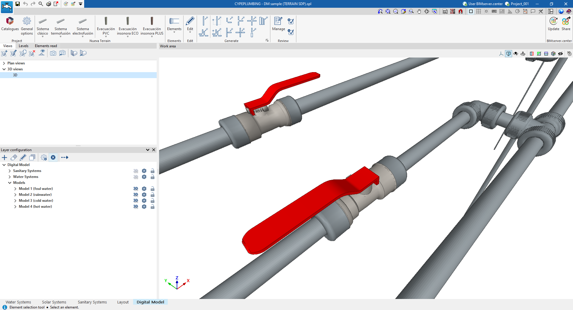
- (Optional) You can track the work process using the detailed model review options (in the "Review" group), which allow the user to colour the parts of the model that are in different review states.
- (Optional) If the model requires it, it may be necessary to return to the analysis tabs, make modifications to the design, and re-export to the "Digital Model" tab. Then, in the "Digital Model" tab, the parts of the installation with changes can be deleted and regenerated.
- Obtaining and exporting results
- Obtaining the reports with the quantities of the pipe parts and fittings (from the "Reports" option in the top bar, in the "Digital Model" tab).
- Obtaining the drawings of the detailed model indicating the reference of the parts and fittings (using the options in the "Layout" tab).
- Obtaining the measurements of parts and fittings in BC3 format (from the "Export in BC3 format" option in the top bar, in the "Digital Model" tab).
- Exporting the detailed model to BIMserver.center (from the "Share" option in the "BIMserver.center" group).
Exporting plumbing systems to the "Digital Model" tab
"Digital Model" option
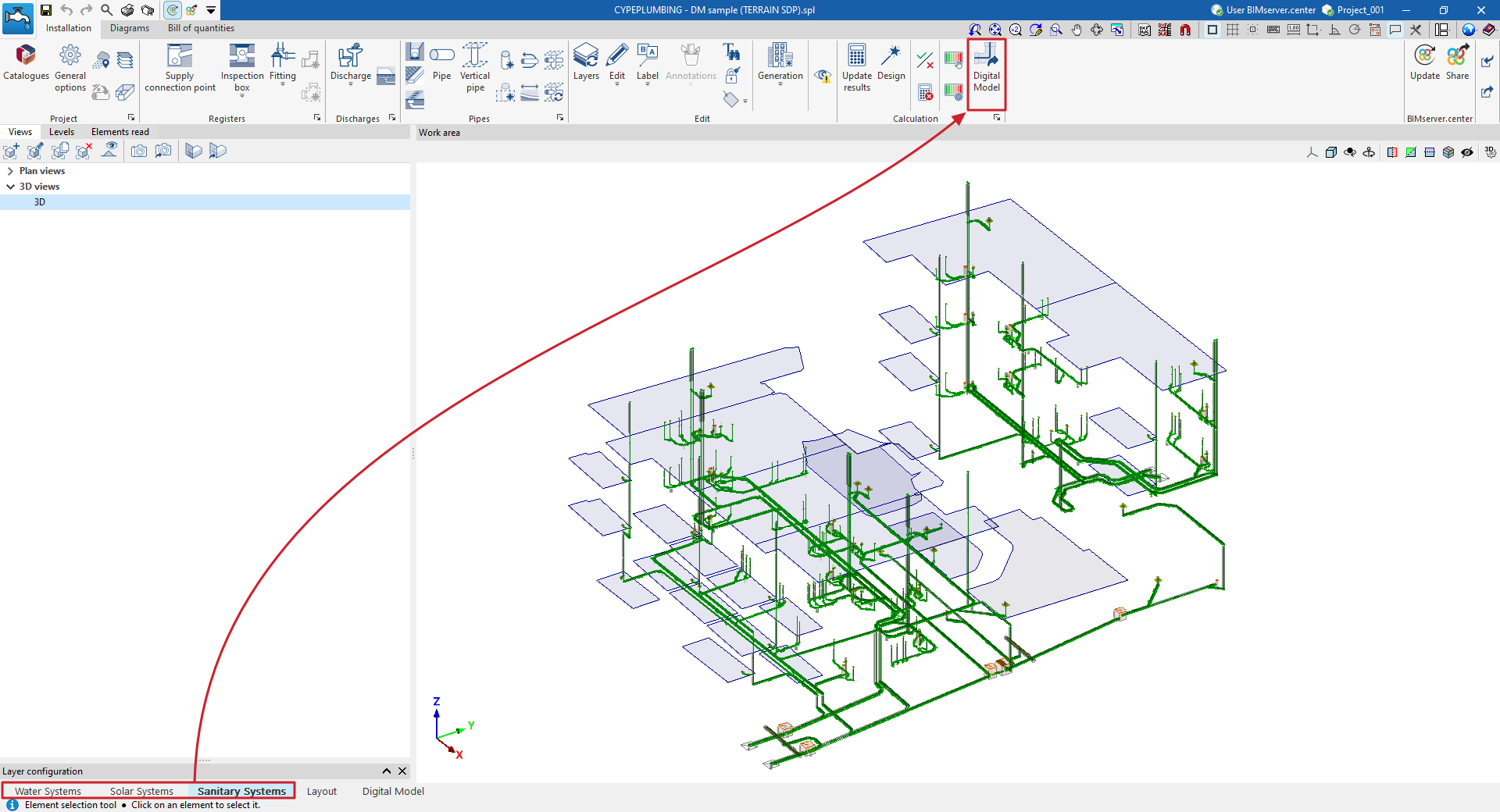
To create a detailed model or breakdown of the water supply, drainage or solar thermal energy systems, you need to export the information from the calculation model created in the "Water Systems", "Sanitary Systems" or "Solar Systems" tabs to the "Digital Mode" tab.
To do this, use the "Digital Model" option in the "Calculation" group of the top toolbar on the "Installation" tab.
| Note: |
|---|
| This action must be performed from each of the different tabs mentioned if you want to create a detailed model of the different systems. |
Detailed model layer configuration
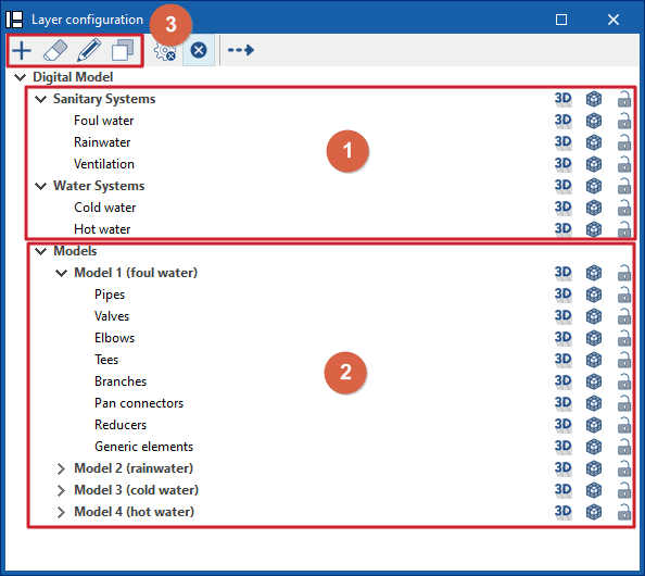
The "Layer Configuration" panel is located by default on the left side of the ‘Digital Model’ tab and offers the following controls.
Display of imported installations (1)
The display of the different installations exported from other tabs can be enabled or disabled using the options in the "Water Systems", "Sanitary Systems" and/or "Solar Systems" lines.
Display and editing of detailed models (2)
The display of the different detailed models generated with the options in the "Generate" group is managed from the lines in the "Models" section.
Editing detailed models (3)
In addition, the options in the top toolbar allow you to "Add", "Delete", "Edit" or "Copy" each of the detailed models generated.
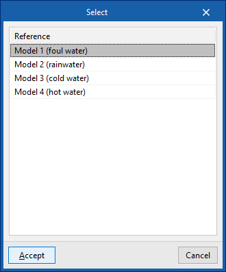
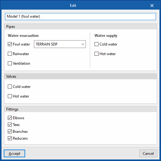
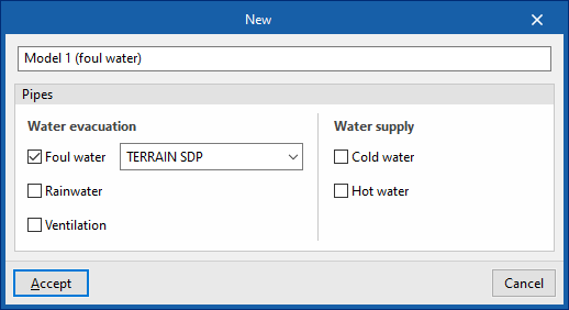
When you click on "Edit", you must choose one of the available detailed models. When you accept, the program opens a pop-up window where you can change its reference, reassign the series of materials to be used in each associated type of installation (in the "Pipes" section), and activate or deactivate the categories of fittings to be generated in the model (in the "Fittings" section).
Available options
The options on the right of this panel allow you to adjust the display and configure the capture of the elements in each category. They are as follows:
 Three-dimensional representation
Enables or disables the three-dimensional or volumetric representation of the elements in the category. Opacity
Adjusts the opacity of the 3D representation of the elements in the category. Capture
Enables or disables the capture of elements in the category.
On the other hand, the "Direction" option at the top of this panel shows the axis of the pipes together with the flow direction calculated in the "Water Systems", "Sanitary Systems" or "Solar Systems" tabs. It is necessary to adjust the opacity of the pipe layers to view it correctly.
Detailed model checks
The "Checks" button at the top of the "Layer configuration" panel opens a window where the following checks can be enabled or disabled for each of the detailed models generated:
- Disconnected elements
- Connections pending solution
- Diameters of elements in contact
- Compatibility of the diameter with the system project
Allows the program to warn that the dimensions of the product in the detailed model do not match those in the design model. In this case, you must return to the corresponding analysis tab, make the necessary changes to check the actual situation, and use the "Digital Model" option again to re-export the information to this tab. - Slope less than 0.5%
- Tolerance for elements in contact
Tolerance value in degrees between parts in contact.
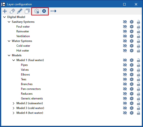
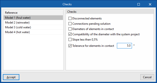
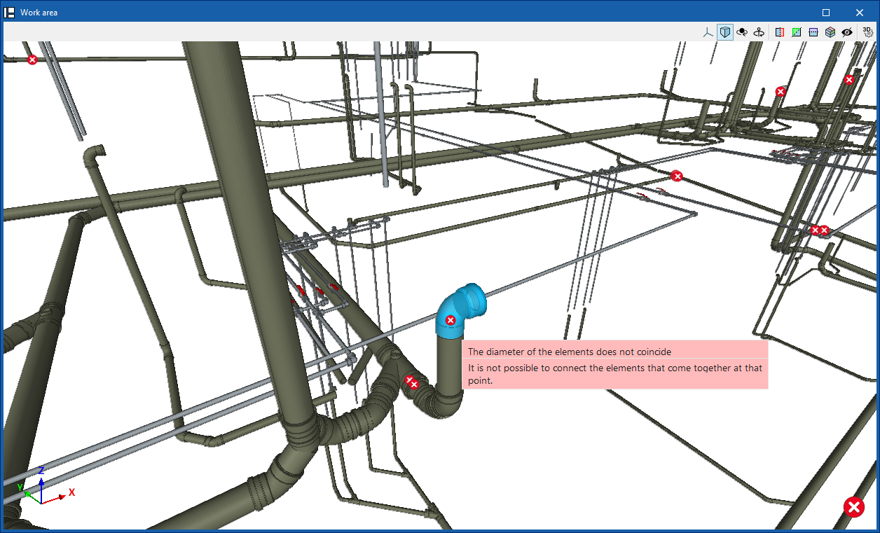
These checks are performed by clicking on the "Check errors" option, also at the top of the "Layer configuration" panel.
Any errors found are displayed on the model elements in the "Work area". Hovering the cursor over each error displays an informative text describing it.
Importing manufacturer catalogues for the detailed model of plumbing systems
In the "Digital Model" tab, manufacturer catalogues are loaded from the "Catalogues" option in the "Project" group at the top so that they are available for use in the detailed model.

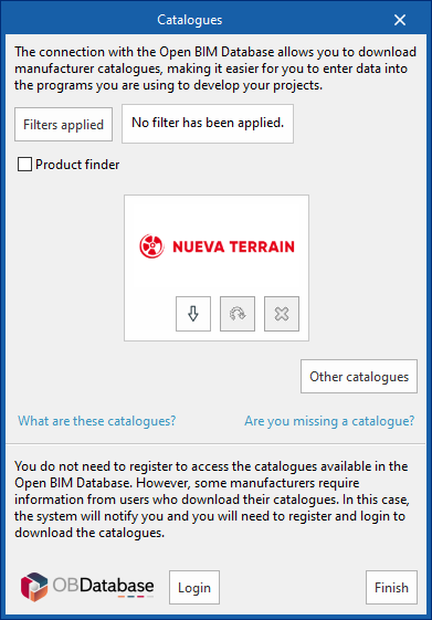
Catalogues
You can download manufacturer catalogues using the connection to the Open BIM Database, making it easier to enter data into the program for project development.
Clicking on this option opens a window with the available manufacturer catalogues.
Using the "Applied filters" option, it is possible to apply filters by "Language" and "Country" to show only those manufacturers that offer product catalogues with these characteristics.
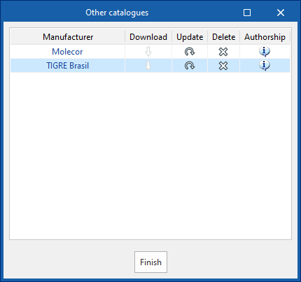
Downloading catalogues
The following options are shown for each manufacturer:
- Download
Downloads the manufacturer's catalogue. The products in the catalogue will be available in the project. - Update
Updates the selected manufacturer's catalogue to the latest version, deleting the downloaded version in the project. - Delete
Deletes the selected manufacturer's catalogue. The products in the catalogue will no longer be available in the project.
Connection to Open BIM Database
At the bottom of this dialogue box, the program allows the user to log in with their Open BIM Database account and password.
Configuring material series for the detailed model
A project may require the combined use of products from different material series (classic system, electrofusion system or thermofusion system; soundproofed or non-soundproofed systems, etc.), depending on the specific needs of each part of the system.
To take this into account in the program, you need to generate lists of specific material series to be used in the detailed model of the project by clicking on "General options" in the "Project" group, within the "Digital Model" tab.

General options
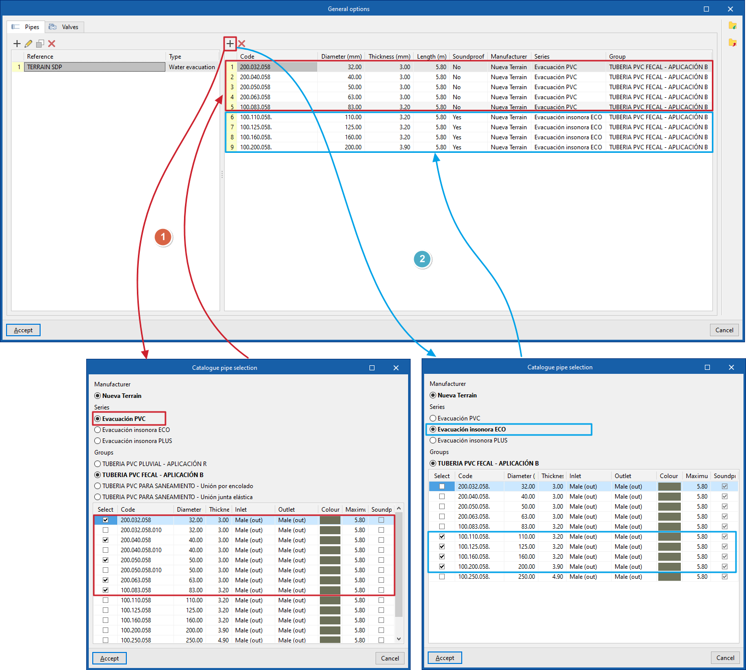
Clicking on this option opens a pop-up window with two tabs, "Pipes" and "Valves".
- In the list on the left, click on ‘Add’ to add a new series to the list. In the "Catalogue pipe selection" or "Catalogue valve selection" window that appears, enter the "Reference" of the series and, in the case of pipes, select the "Type of installation", either "Water drainage", "Solar thermal collection" or "Water supply".
- Once the series has been created in the list on the left, the materials that comprise it must be added to the list on the right. To do this, use the tools at the top. This allows you to select a "Manufacturer" and one of the available "Series" and "Groups". At the bottom, tick the boxes in the "Select" column for the specific products you want to add to the series of materials to be used in the project. Then click on "Accept". This operation can be repeated as many times as necessary until the specific series of materials to be used in the project is complete.
The series created can be "Imported" and "Exported" to files on disk (with the extension .bib905) using the options on the right-hand side so that they can be used in other projects.
| Note: |
|---|
| The series of materials to be used on the project may be composed of materials corresponding to different manufacturer series, and even from different manufacturers. For example, when defining pipe materials for a wastewater system, you can import products from a manufacturer's non-soundproofed series up to a certain diameter (such as 83 mm), and then incorporate products from the soundproofed series above that diameter. |
Inserting individual elements into the detailed model
The options in the "Elements" group in the top toolbar of the "Digital Model" tab allow you to manually insert individual parts and fittings to complete the detailed model.

Inserting elements individually is particularly useful when the automatic processes in the "Generate" group options have not been able to correctly resolve certain points in the system.
Elements
The following elements are available:
- Pipe
- Valve
- Elbow
- Tee
- Branch
- Pan connector
- Reducer
- Generic element
Includes elements such as grafts, cleanout branches, floor trap, connectors, aeration terminals or drains.
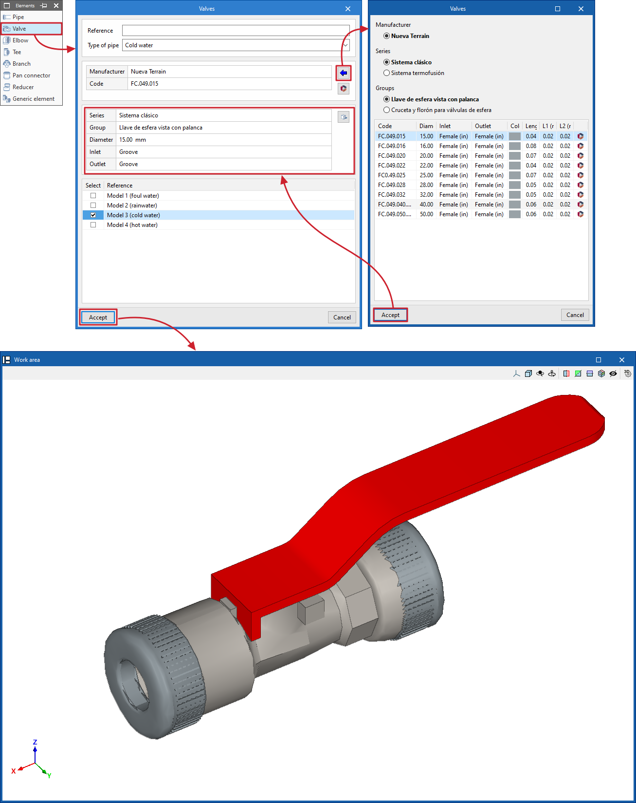
When you select any of these, a window opens where you can enter a "Reference" for the element and select the "Installation type" and "Pipe type" from those available.
Next, a specific product from a "Manufacturer" is selected using the data import button on the right. The program also allows "Catalogues" from Open BIM Database manufacturers to be downloaded and updated from this window.
Below, the program displays information about the selected product, as well as a "3D View".
At the bottom, you must "Select" the detailed model in which you want to incorporate the element; after clicking "Accept", it will be available in the work area.
The orientation and layout of the element can be adjusted later using the tools in the "Edit" group.
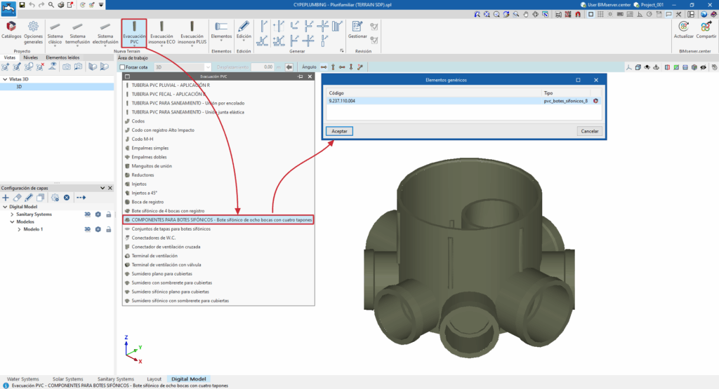
Manually entering manufacturer elements in the detailed model
In the "Digital Model" tab, after downloading a specific manufacturer's catalogue using the "Catalogues" option, when you restart the program, a specific group of options will appear in the toolbar at the top of the interface.

These options allow you to select and manually enter parts and fittings from that manufacturer individually to complete the detailed model.
Selecting and entering manufacturer elements using these options is similar to doing so from the generic "Elements" menu. In this case, direct access to each manufacturer's products speeds up the work.
Detailed model editing tools
The options in the "Edit" group of the main toolbar in the "Digital Model" tab allow you to perform operations on the elements that make up the detailed model of the system.

These are as follows:
| Edit | Edits the parametric properties of the selected element in the model. | |
| Delete | Deletes a previously entered element. | |
| Rotate element | Rotates an element around the "x", "y" or "z" axes. | |
| Rotate a group of elements | Rotates a group of elements. | |
| Move element | Moves an element or a node of an element. | |
| Move a group of elements | Moves a group of elements. | |
| Copy | Creates a copy of one or more elements. | |
| Insert node | Inserts an intermediate node into a pipe and divides it into two. | |
| Join elements | Joins two selected pipes. | |
| Measure lengths on the plane | Measures lengths and angles between points defined in the model. If a closed contour is selected, it also indicates the area. | |
| Projection | Switches to the plan projection (XY plane) in the work area. | |
| Reverse direction | Reverses the direction of the selected pipes. | |
| Join pipes | Extends two selected pipes to their point of intersection. | |
| Reverse the type of outlets (male-female) | Reverses the male-female outlets of the selected pipes. |
Generating detailed models of plumbing systems
The "Generation" group on the top toolbar offers the following options for generating the breakdown of the pipes and fittings that make up the different systems in the project.

Options for generating pipes and fittings for the entire project
The first two options available allow you to generate pipes and fittings for the entire project:
- Pipes
Generates the details of all the parts that make up all the pipes in the project. In the pop-up window, you must indicate the reference of the detailed model generated, and then, for each type of installation, you must select a specific series of materials from those previously created in the "General options". - Fittings
Generates the fittings required throughout the installation for the selected detailed model, including "Elbows", "Tees", "Branches" and "Reducers", by ticking the corresponding boxes.
| Note: |
|---|
| The usual workflow involves generating all the pipes in the detailed model and then generating all the fittings in the model, using these two options consecutively. |
Options for generating parts of the detailed model
In addition to these options for generating all elements of the project, it is possible to use the following options for partial generation only on the elements selected by the user in the work area:
- Pipes
Generates the details of the parts that make up the pipes selected by the user. - Fittings
Generates the necessary fittings in the elements selected by the user. - Elbows
Generates elbows in the elements selected by the user. - Tees
Generates tees in the elements selected by the user. The program offers two different options, which allow tees to be generated between two pipes or between three pipes. - Branches
Generates branches in the elements selected by the user. The program offers two different options, which allow branches to be generated between three pipes or between four pipes. - Reducers
Generates reducers in the elements selected by the user.
| Note: |
|---|
| If the program cannot find a solution for a particular joint, it displays the message "There are no fittings in the catalogue with which the selected pipes can be joined". In these cases, the user can try to work around the situation by modifying the design, for example, by inserting a reduction beforehand to ensure that the connection to be resolved is made between pipes of the same diameter, and then resolving the connection between the desired pipes. |
Regeneration of the detailed model
The "Model" option allows you to recalculate the distances of the pipes and regenerate their layout.
This is necessary if changes have been made manually to the automatically generated installation.
Detailed model review tools
The options in the "Review" group of the top toolbar in the "Digital Model" tab make it easier to visually check and review the elements of the detailed model using a colour-coding system.

Review management
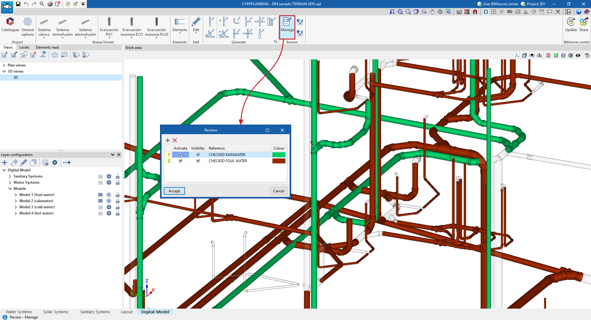
The "Manage" option opens a window where different review statuses can be added.
Each of these is characterised by a "Reference" and a "Colour". You can also indicate whether you want to "Activate" and adjust the "Visibility" of the elements associated with it.
Assigning and removing elements from revisions
Next, the "Assign" and "Remove" options allow you to add or remove elements from the detailed model to a specific revision status.
This way, you can create review statuses with distinctive colours and assign them to the model elements that have already been reviewed. This allows you to visually track the parts of the installation you have already worked on.
Detailed model results output
Detailed model listings
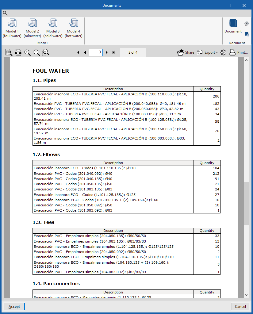
The "Reports" option at the top of the "Digital Model" tab opens the "Documents" window.
From here, using the options in the "Model" group on the top toolbar, you can generate a "Bill of materials" report for each of the detailed models generated. These reports include the quantities of all the parts and fittings for the designed systems.
To compose a single document with information from several models, use the "Document" option in the same window.
| Note: |
|---|
| This information can be given to each manufacturer to request a bill of quantities for the system. To do this, you can first create different detailed models using different manufacturers to obtain the reports needed for comparison. |
Detailed model plans
The drawings of the detailed model designed in the "Digital Model" tab can be generated and obtained from the "Layout" tab.
To do this, follow these steps:
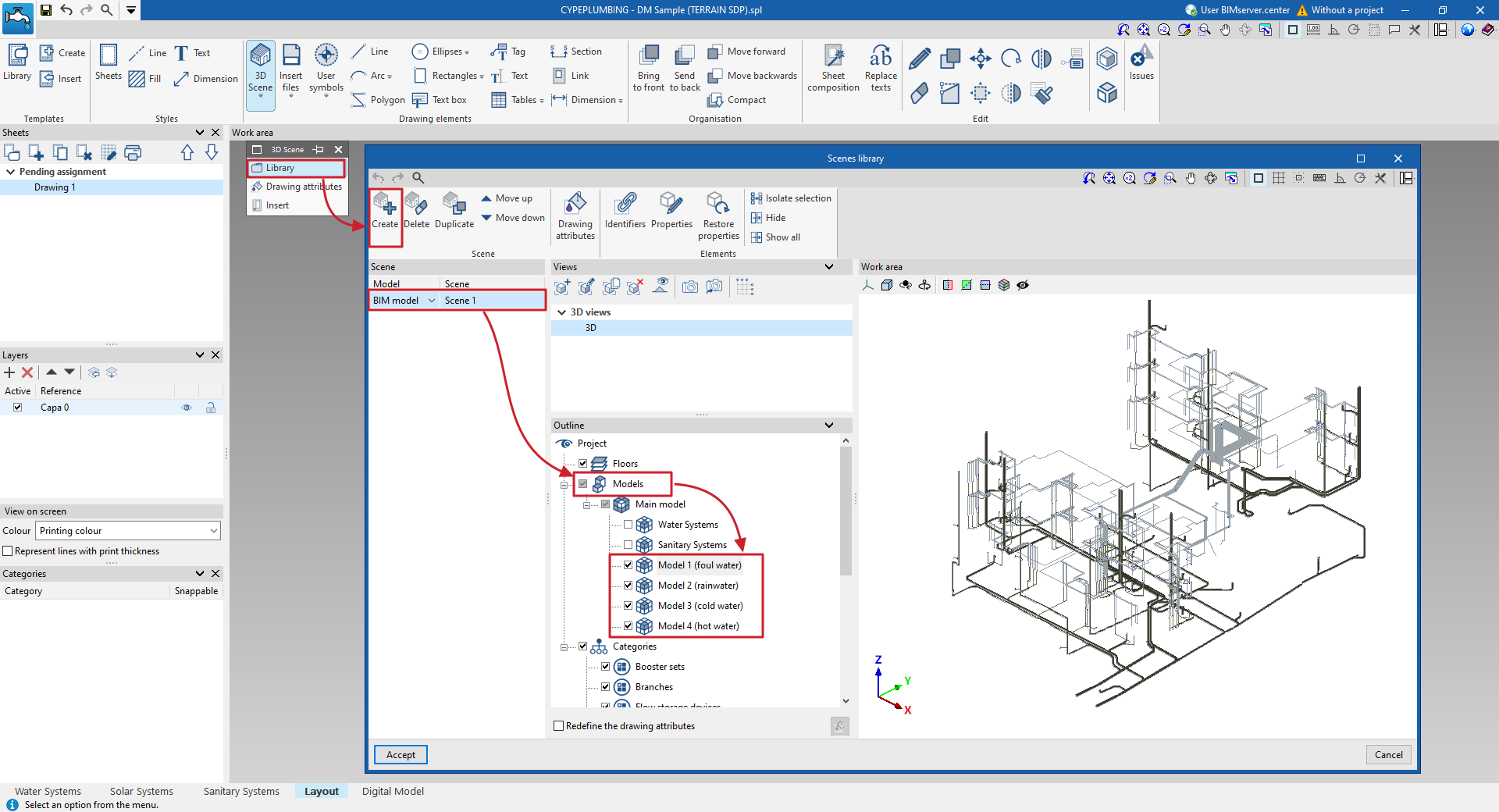
- First, from the scene library ("3D Scene", "Scene Library"), create a scene associated with each detailed model (by clicking on "Create" and, in the "Diagrams" panel, selecting one of the available detailed "Models").
- Then, insert the scene into the sheet ("3D Scene", "Insert Scene").
The program then generates the detailed model scene and automatically labels its components.
If necessary, you can use the options in the top bar to add or remove labels, or modify the rest of the information in the plan.
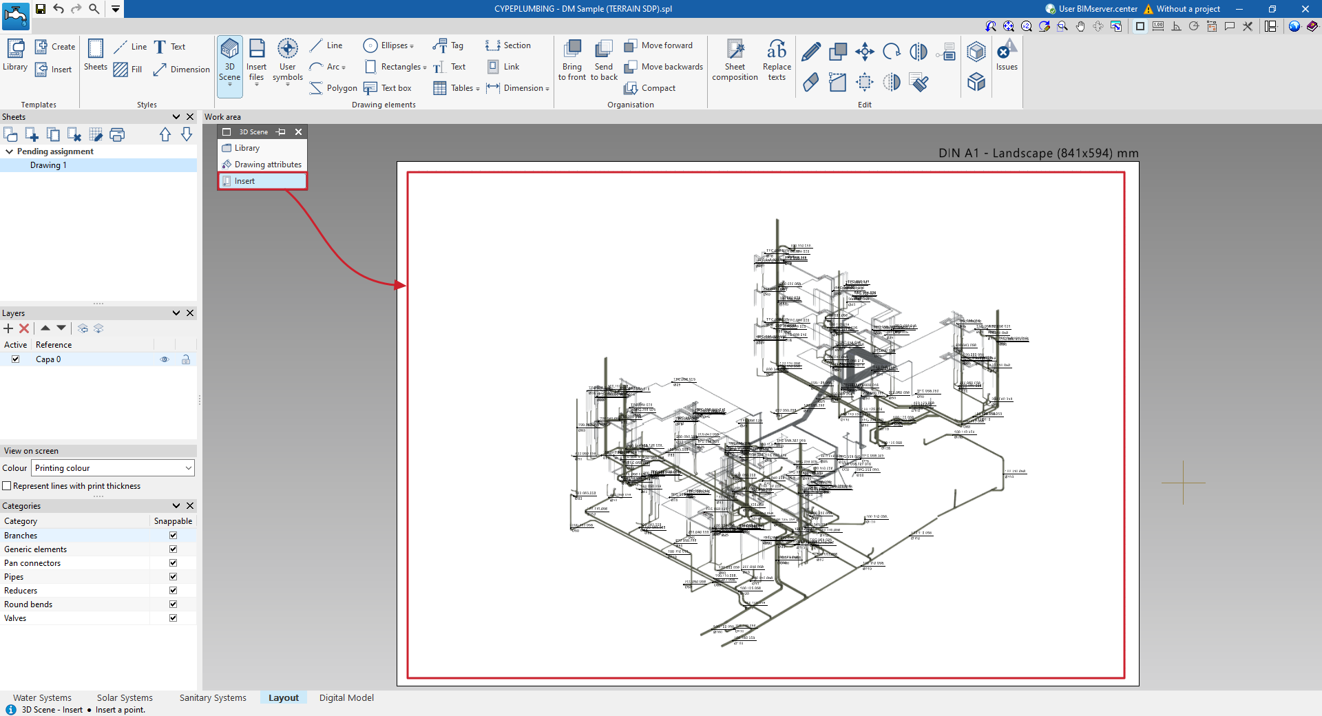
Process for creating and inserting 3D scenes of the detailed model with automatically generated labels
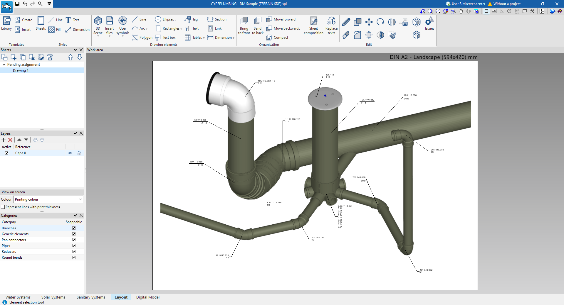
Example of a sheet with scene and labels entered manually
Quantities in the detailed model in BC3 format
The program allows you to obtain the quantities of the parts and fittings of the detailed model in FIEBDC-3 (BC3) format using the "Export in BC3 format" option in the top bar, in the "Digital Model" tab.
Files in BC3 format can be imported and worked with in any program capable of managing estimates, including the "Bill of quantities" tab available in CYPEPLUMBING.
File .gltf compatible with BIMserver.center
When exporting the project to the BIMserver.center platform, it is possible to incorporate the export of the detailed model created in the "Digital Model" tab by ticking the corresponding box.
This automatically exports a 3D model in GLTF format for the integration of the detailed model of the installation into the Open BIM project, allowing it to be viewed:
- On the online platform
- In the BIMserver.center application for iOS and Android
- In virtual reality and augmented reality
- In other CYPE programs
Table of contents
Complete your tour of CYPEPLUMBING by exploring the other sections available: