
"Solar Systems" tab work environment
The interface of the "Solar Systems" tab in the CYPEPLUMBING program has three tabs at the top with different work environments: "Installation", "Diagrams" and "Bill of quantities". These environments are similar to those in other CYPE tools and have a system of dockable windows that can be customised to adapt the workspace to the needs of the project.
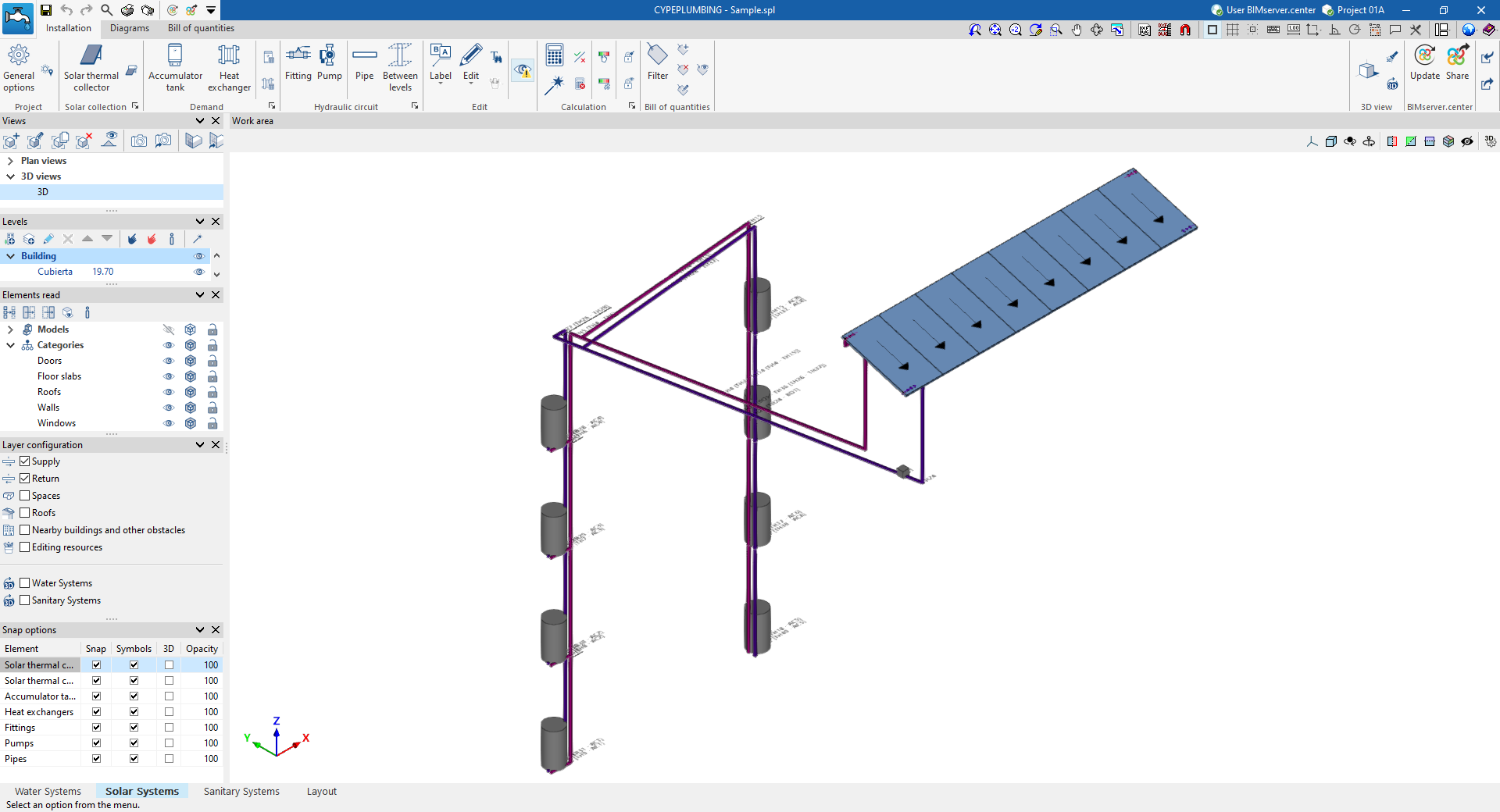
"Installation" tab
The "Installation" tab has a work environment that can be used to design the solar thermal energy system, both in a 3D view and in any type of 2D view (such as floor plans and elevations). This way, the elements in the system can be entered using the most appropriate view at any given time.
This tab contains:
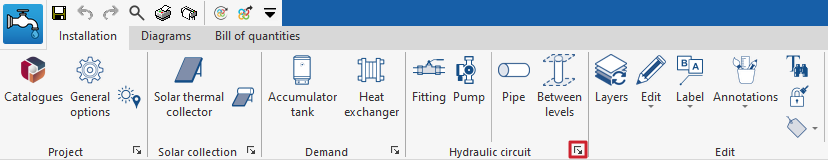
- A top toolbar containing the tools for managing the catalogues and project options; entering and editing the elements of the solar thermal energy system (solar thermal collectors; accumulator tanks and heat exchangers; fittings, pumps and pipes); and analysing, checking and sizing the system.
- The work area, on the right-hand side of the screen, where the above-mentioned elements are entered, edited and displayed.
- On the left-hand side, several panels with tools for defining the views and levels of the project, managing the visibility of the elements read and configuring the layers and snap options.
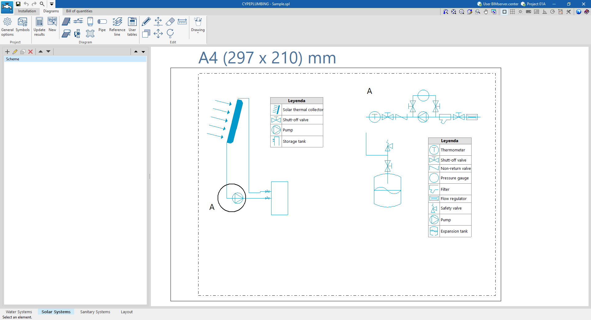
"Diagrams" tab
The "Diagrams" tab contains a work environment that generates the diagrams of the solar thermal energy system and creates them on sheets in the desired formats.
This tab contains:
- A top toolbar containing the tools for generating the solar thermal system diagrams; entering and editing the elements that make up the diagrams; and adjusting and configuring the general options and symbols.
- The workspace, on the right of the screen, where the system diagrams are entered, edited and displayed.
- On the left-hand side, a navigation panel between the different diagrams created, which are made up of sheets of editable format and scale.
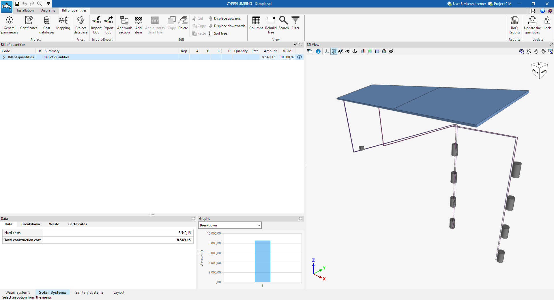
"Bill of quantities" tab
On the other hand, the "Bill of quantities" tab is used to manage the quantities and bill of quantities of solar thermal energy systems, and it shows the following:
- A top toolbar containing the tools for creating and editing the bill of quantities, as well as those for managing and creating reports.
- A graphic window with its own toolbar, located on the right-hand side, in which it is possible to visualise the different elements of the job.
- A specific area for structuring the bill of quantities, on the left-hand side.
Data input and output sequence for the design and analysis of solar thermal systems
The solar thermal system can be defined and analysed in the "Solar Systems" tab of the program using the following sequence of data input and output:
- Creating a new project (from "File", "New").
- (Optional) Linking to BIMserver.center, import of the geometric model, and definition of the configuration and applicable standards.
- (Optional) Reviewing and configuring manufacturer catalogues (under "Project", "Catalogues").
- Reviewing and configuring general options (under "Project", "General options").
- Defining the town/city (from "Project", "City").
- Laying out the solar thermal collectors in the work area (options in the "Solar collection" group).
- Laying out heat exchangers and accumulators in the work area. This can be done in several ways:
- Using the storage tanks and heat exchangers automatically generated from the DHW production units and heat exchangers entered in the "Water Systems" tab.
- Entering the heat accumulators and heat exchangers manually (options in the "Demand" group).
- (Optional) Laying out the components and pumps included in the solar thermal system within the work area (options in the "Hydraulic circuit" section).
- Connecting pipes between the solar thermal collectors, storage tanks and heat exchangers, and the other equipment installed (options in the "Hydraulic circuit" section)
- Analysing, checking and designing model elements, and viewing results (the "Analysis" group).
- (Optional) Managing and generating installation diagrams (the "Diagrams" tab).
- (Optional) Managing and generating bills of quantities (the "Bill of quantities" tab).
- Viewing reports and drawings (via the "Reports" and "Drawings" options on the top menu bar).
- Exporting to BIMserver.center (from "BIMserver.center", "Share").
Examples of solar thermal installation diagrams
Below are several diagrams of solar thermal installations that can be created in the program, showing the layout of the components and the options available for adding them to the model:
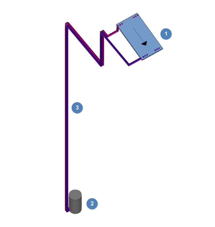
Installation of a split-system unit
Schematic diagram of a solar thermal installation for a small, single-owner office building.
- Solar thermal collector (under "Solar energy collection", "Solar thermal collector").
- Single-circuit heat exchanger (in "On-demand", "Storage" modes).
- Supply and return pipes ("Hydraulic circuit", "Pipe").
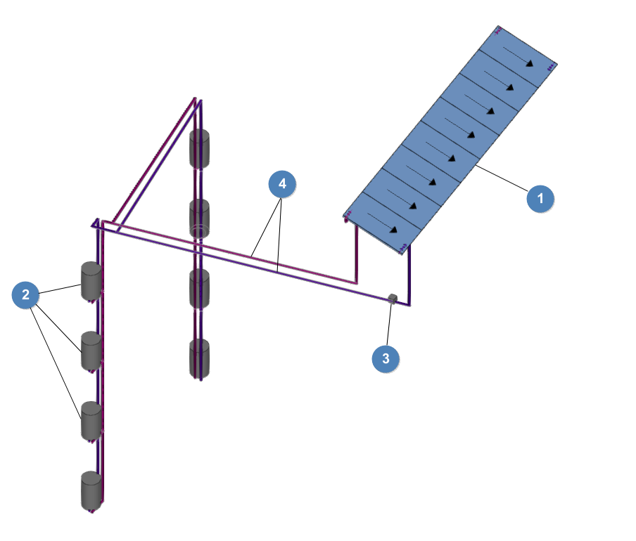
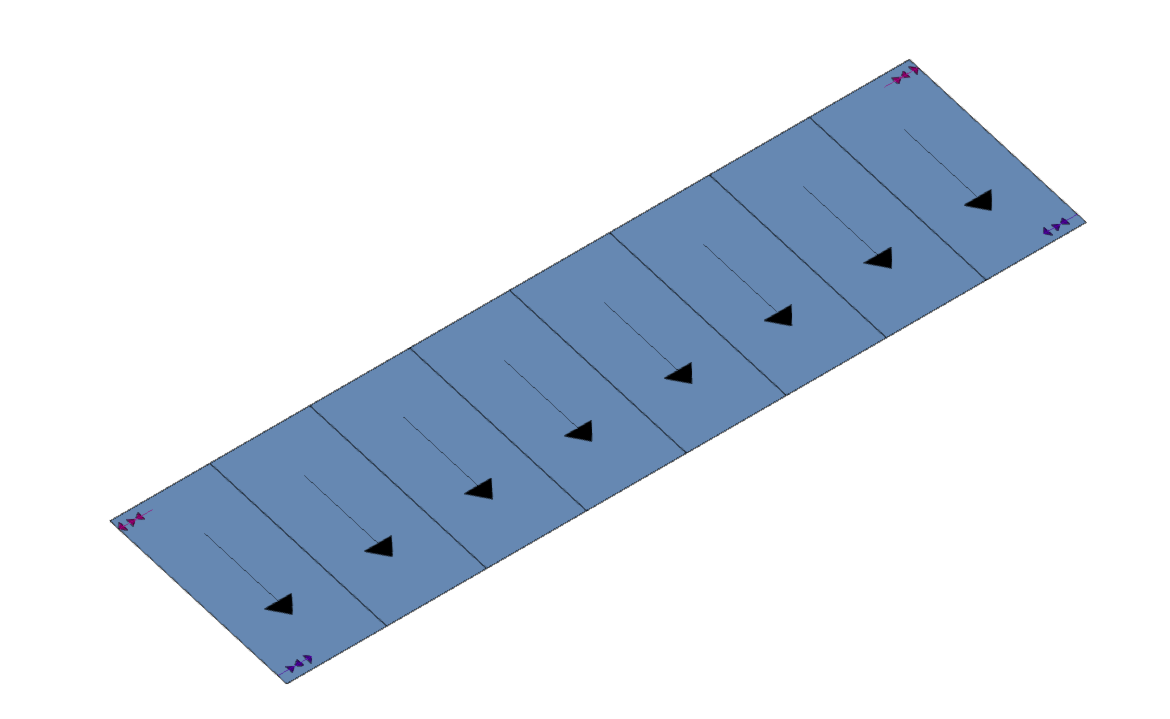
Installation of multiple units with individual heat storage tanks
Schematic diagram of a solar thermal installation for an eight-unit apartment block.
- Solar thermal collectors (under "Solar collection", "Solar thermal collector").
- Single-pass heat exchangers, for individual use (in "On-demand" or "Storage" mode).
- Circulation pump (under "Hydraulic circuit", "Pump").
- Supply and return pipes (under "Hydraulic circuit", "Pipe").
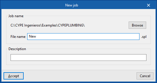
Creating a new job, linking to a project and importing data
When starting the application and clicking on "New", it offers users the chance to create a "New job", which can then be integrated into an existing project in BIMserver.center.
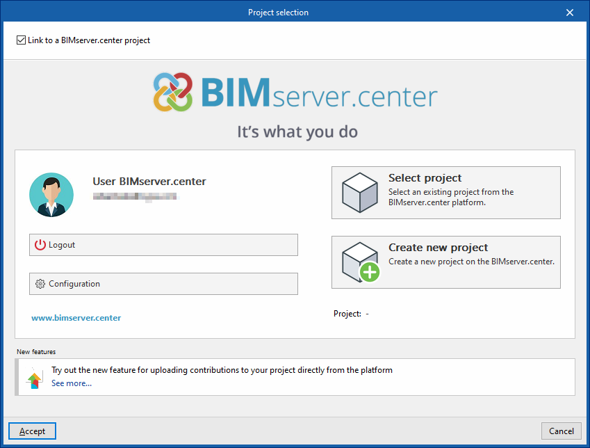
This is selected in the "Project selection" window. On the left-hand side, the user can log in with their BIMserver.center account.
Users can also "Create a new project". In this case, the created project will be visible from BIMserver.center from that moment on.
There is also the option of starting the project without being linked to the BIMserver.center platform. To do this, simply uncheck the box at the top left, "Link to a BIMserver.center project".
Once the new job has been created, the program interface is accessed, which includes a graphic window showing the model or models that have been imported.
At any time during the project, files can be shared or imported via the "BIMserver.center" group at the top right-hand side of the screen.
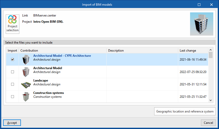
Importing BIM models
When creating a new job and selecting a project hosted on the BIMserver.center platform from "Select project", the "Import BIM models" window appears, which shows the files contained in that project in IFC format.
The application allows users to include one or more of the existing models in the project. To do this, the "Import" box is checked and accepted.
When accessing the interface, the graphic window will display the imported models. In addition, if they contain this information, it will create the views, levels and floor plans necessary for developing the system model.
Importing configuration
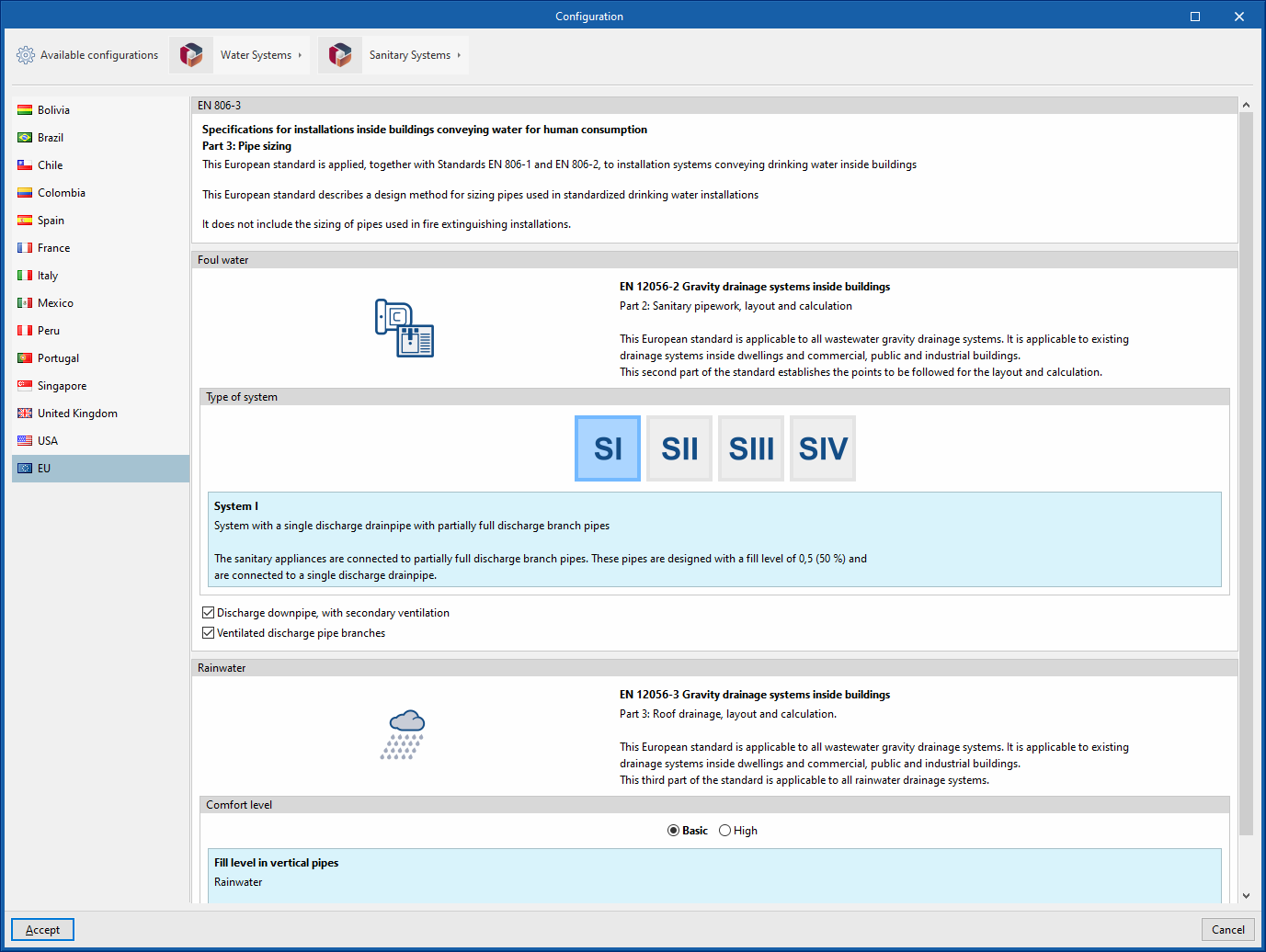
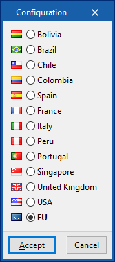
Further on, the program opens the "Configuration" window, which allows the following:
- In the central part, users can select the configuration and the applicable codes from those available for different countries and regions. The selection is made for both the water supply system, developed in the "Water Systems" tab, and the water evacuation system, developed in the "Sanitary Systems" tab.
- The configuration provided by different manufacturers can also be imported via the "Available configurations" menu at the top left.
- Finally, the "Water Systems" and "Sanitary Systems" menus at the top allow the download and management of catalogues of different elements of the water supply and drainage systems.
If this window is closed or cancelled, the program will create the job without importing any settings.
If users wish to subsequently load the configuration or customise it, or manage the job catalogues, they can use the "General options" and "Catalogues" tools in the top toolbar of the "Installation" tab, available in the "Water Systems" and "Sanitary Systems" tabs, respectively.
| Note: |
|---|
| The following link can be consulted for the codes implemented in the program. |
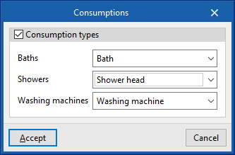
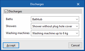
Generating consumptions and discharges from sanitary equipment
If the BIM model contains information on the sanitary appliances, when creating a new job, the program offers to associate them with the consumption and discharge types defined in the configuration of the building. This automatically generates the consumption and discharge points and arranges them in the model space.
| Note: |
|---|
| The following link can be consulted to learn about entering sanitary equipment and other elements in CYPE Architecture. |
Managing manufacturers' catalogues
In the "Catalogues" group of the main toolbar of the "Installation" tab, either in the "Water Systems" tab or in the "Sanitary Systems" tab, there are tools for managing manufacturers' catalogues in the water supply or water evacuation system, respectively:


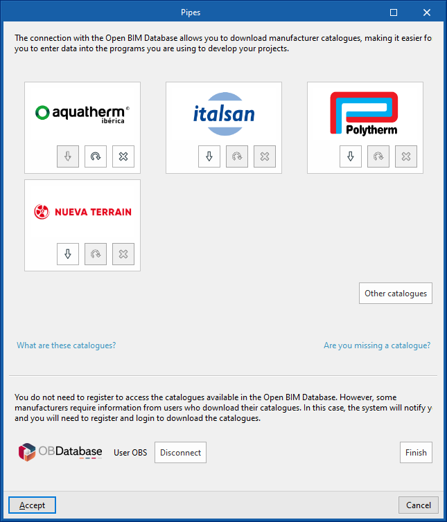
Catalogues
Downloads manufacturers' catalogues using the Open BIM Database connection, making it easier to enter data into the program for the project development.
Clicking on this option opens a menu where the desired element can be selected. When doing this, a window opens with the available manufacturer's catalogues for that element.
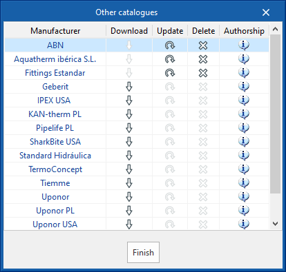
Download catalogues
The following options are shown for each manufacturer:
- Download
Download the manufacturer's catalogue. The products in the catalogue will be available in the project. - Update
Updates the selected manufacturer's catalogue to the latest version, deleting the version downloaded in the project. - Delete
Deletes the selected manufacturer's catalogue. The products in the catalogue will no longer be available in the project.
Connection to Open BIM Database
At the bottom of this dialogue box, the program allows users to log in with their Open BIM Database account and password.
Importing catalogue data
The manufacturers' catalogues downloaded in the project are available when creating materials and equipment for the elements in the system from the different options in the “Material and equipment selection” section of the “General options”, using the “Available manufacturers” button located at the top right of each table.
From here, catalogues can also be downloaded, using the "Catalogues" button next to the one above.
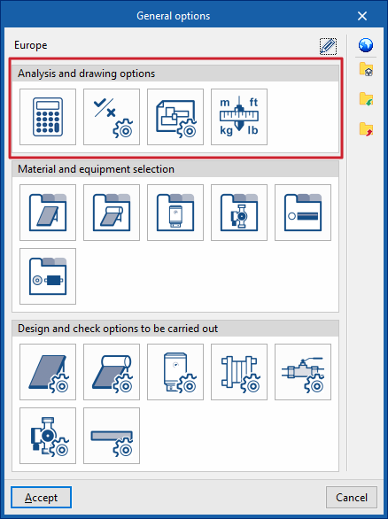
Configuring drawing and analysis options for solar thermal installations
Under the "Installation" tab in the "Solar Systems" section, within the "General options" of the "Project" group on the main toolbar, you can configure the "Analysis and drawing options" for the solar thermal installation:

- Analysis options
- General checks
- Display options
- Units
If you use the "Import configuration" option, located to the right of the "General options" panel, you can automatically generate this data for different countries and national and international regulations.
The other options in the right-hand column allow you to import and export the complete settings from the "General options" panel to files on your hard drive, as well as to select a file containing default values when creating a new project.
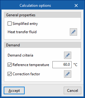
Calculation options
This allows you to define the general data and calculation criteria for the solar thermal installation:
- General Features
- Simplified entry (optional)
If this option is enabled, the input and editing panels for installation elements have a simplified layout and do not require certain parameters to be defined. - Heat transfer fluid
This allows you to define the volumetric density, specific heat and viscosity of the heat transfer fluid for each temperature value.
- Simplified entry (optional)
- Demand (optional)
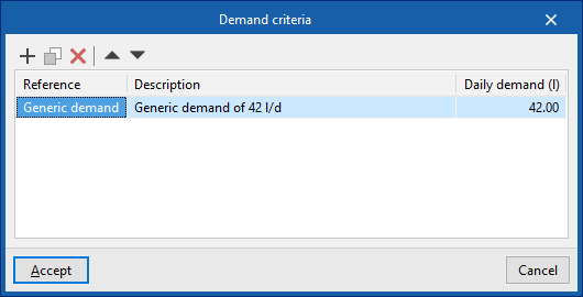
- Demand criteria
This allows you to define the demand criteria for the available DHW (for example, for each unit of use in a residential building, a hotel, a gym, etc.), specifying its reference, description and daily demand per unit (in volume units). These criteria can subsequently be selected to enter the necessary information in the ‘Consumption’ section of the ‘Storage tank’ or ‘Heat exchanger’ equipment. - Reference temperature (optional)
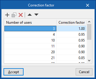
Allows you to set the reference temperature for the DHW demand. - Correction factor (optional)
Allows you to define a correction factor for DHW demand based on the number of users.
- Demand criteria
General checks
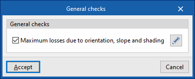
This allows you to define the general checks for a solar thermal installation:
- General checks
- Maximum losses due to orientation, slope and shading (optional)
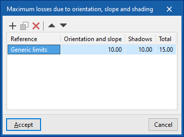
Allows you to define the values for the following maximum losses for different scenarios (such as the general case, the case of overlapping collectors or the case of architectural integration of collectors):- Losses due to "Orientation and slope"
- Losses due to "Shadows"
- Losses under "Total"
- Maximum losses due to orientation, slope and shading (optional)
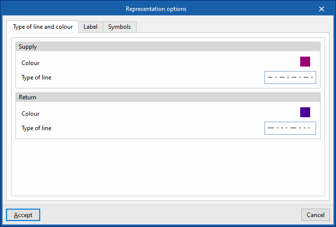
Representation options
This allows you to configure the graphical display of the components of the solar thermal system
- "Type of line and colour" tab:
Changes the line type and colour used in the graphical representation of the different types of pipes.- Drive (Colour, Line type)
- Return (Colour, Line type)
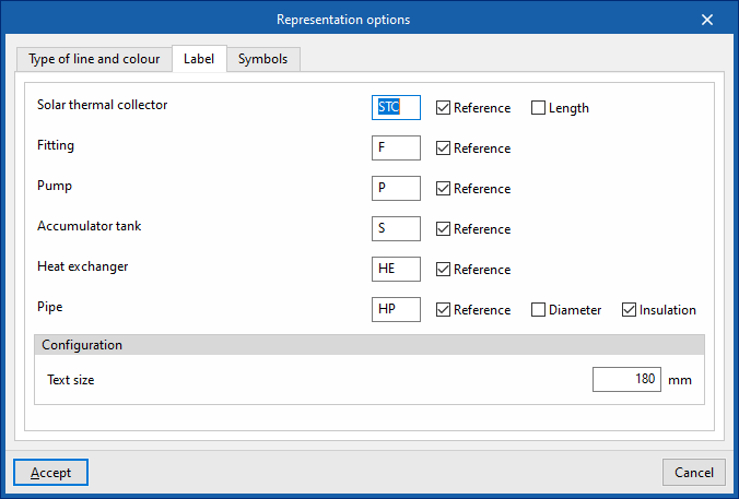
- "Label" tab:
Customises the information displayed on the labels for the various components of the solar thermal system, as well as the text size.- Components (Solar thermal collector, Fittings, Pump, Storage tank, Heat exchanger, Piping)
- settings
- Text size
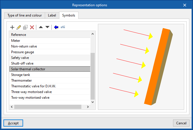
- "Symbols" tab:
Allows you to create custom symbols using a drawing editor or import symbols contained in DXF, DWG or DWF files saved to disk.
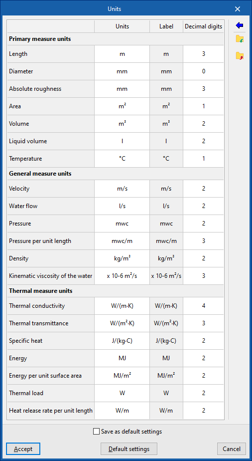
Units
This allows you to configure the units, the label and the number of decimal places for each of the parameters relating to the solar thermal installation:
- Primary measure units (Length, Diameter, Absolute roughness, Area, Volume, Liquid volume, Temperature)
- General physical quantities (Velocity, Water flow rate, Pressure, Pressure per unit length, Density, Kinematic viscosity of water)
- Thermal measure units (Thermal conductivity, Thermal transmittance, Specific heat, Energy, Energy per unit surface area, Thermal load, Heat release rate per unit length)
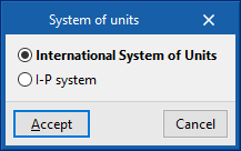
If you use the "Import one of the predefined unit systems" option, available on the right-hand side of the panel, you can import one of the following unit systems:
- International System of Units
Allows you to import units from the International System. - I-P System
Allows you to import units from the I-P (Inch-Pound) system or the imperial system.
Selecting materials and equipment for a solar thermal installation
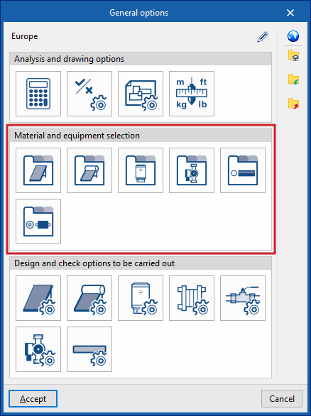
Under the "Installation" tab in the "Solar Systems" section, within the "General options" of the "Project" group on the main toolbar, you can select the materials and equipment for the following components of the solar thermal installation:
- Solar thermal collector catalogue
- Catalogue of solar thermal collectors with storage tanks
- Battery catalogue
- Pump catalogue
- Pipe catalogue
- Thermal insulation catalogue
If you use the "Import settings" option, located to the right of the "General options" panel, you can automatically generate this data for different countries and national and international regulations.
The other options in the right-hand column allow you to import and export the complete settings from the "General options" panel to files on your hard drive, as well as to select a file containing default values when creating a new project.
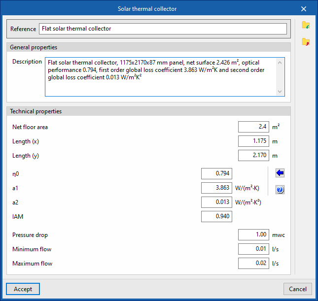
Solar thermal collector catalogue
This allows you to define the range of solar thermal collectors available on site. These elements are subsequently added to the model using the "Solar thermal collector" option in the "Solar collection" group.
When defining solar thermal collectors in this section, the following parameters must be specified:
- Reference:
Reference number for the material or equipment. - General features
- Description
- Technical specifications
Enter the technical specifications of the solar thermal collector:- Effective area
Effective area of the collector. - Length (x)
Length of the sensor in its local "x" direction. - Length (y)
Length of the sensor in its local "y" direction. - η0
Optical efficiency of the collector. The wizard on the right allows you to import standard values for different types of collectors, such as vacuum tube solar collectors (with flat or circular absorbers), flat-plate collectors with glass, or collectors without glass. - a1 First-order overall
loss coefficient. - a2 Overall
second-order loss coefficient. - IAM Angle of incidence
modifier. - Pressure drop
Pressure drop associated with the collector. - Minimum flow rate
Minimum flow rate required at the collector. - Maximum flow rate
Maximum flow rate permitted in the collector.
- Effective area
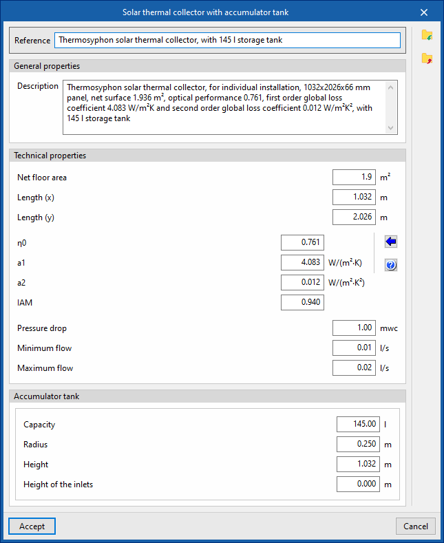
Catalogue of solar thermal collectors with storage tanks
This allows you to define the range of solar thermal collectors with storage tanks available on site, including compact thermosiphon systems. These elements are subsequently added to the model using the "Solar thermal collector with storage tank" option in the "Solar collection" block.
When defining solar thermal collectors with storage tanks in this section, the following parameters must be specified:
- Reference:
Reference number for the material or equipment. - General features
- Description
- Technical specifications
Enter the technical specifications of the solar thermal collector:- Effective area
Effective area of the collector. - Length (x)
Length of the sensor in its local "x" direction. - Length (y)
Length of the sensor in its local "y" direction. - η0
Optical efficiency of the collector. The wizard on the right allows you to import standard values for different types of collectors, such as vacuum tube solar collectors (with flat or circular absorbers), flat-plate collectors with glass, or collectors without glass. - a1
First-order overall loss coefficient. - a2
Overall second-order loss coefficient. - IAM
Angle of incidence modifier. - Pressure drop
Pressure drop associated with the collector. - Minimum flow rate
Minimum flow rate required at the collector. - Maximum flow rate
Maximum flow rate permitted in the collector.
- Effective area
- Battery
Allows you to enter the battery specifications:- Capacity
The capacity of the accumulator, expressed in units of volume. - Radius
from the storage tank. - Height
Height of the storage tank. - Height of the inlets
The height of the storage tank’s connection points relative to its base.
- Capacity
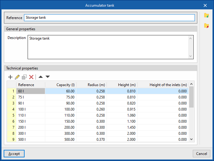
Accumulator tank catalogue
This allows you to define the list of accumulator tanks available on site. These elements can subsequently be added to the model using the "Accumulator tank" option within the "Demand" section.
When defining the accumulators in this section, you must specify the following parameters:
- Reference:
Reference number for the material or equipment. - General features
- Description
- Technical specifications (Model / Capacity / Radius / Height / Height of the inlets)
Allows you to enter the technical specifications of the series’ storage tanks by adding entries to the table.
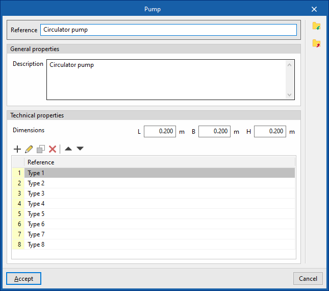
Pump catalogue
This allows you to define the range of circulation pumps available on site. These elements are subsequently added to the model using the "Pump" option in the "Hydraulic circuit" group.
When specifying circulation pumps in this section, the following parameters must be provided:
- Reference
Reference number for the material or equipment. - General features
- Description
- Technical specifications
Allows you to enter the pump’s technical specifications.- Dimensions (L, W, H)
- Flow/pressure curve This
allows you to define the flow/pressure curves available for the circulation pump by adding entries to the table.- Reference
Curve reference. - Curve type
- Midpoint
Allows you to enter the values that define the midpoint of the flow/pressure curve and displays a graph showing the associated curve.- Flow rate
- Pressure
- By points:
Allows you to enter flow/pressure pairs and displays a graph showing the corresponding curve.- Flow rate
- Pressure
- Midpoint
- Reference

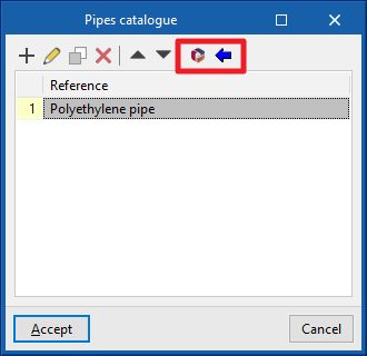
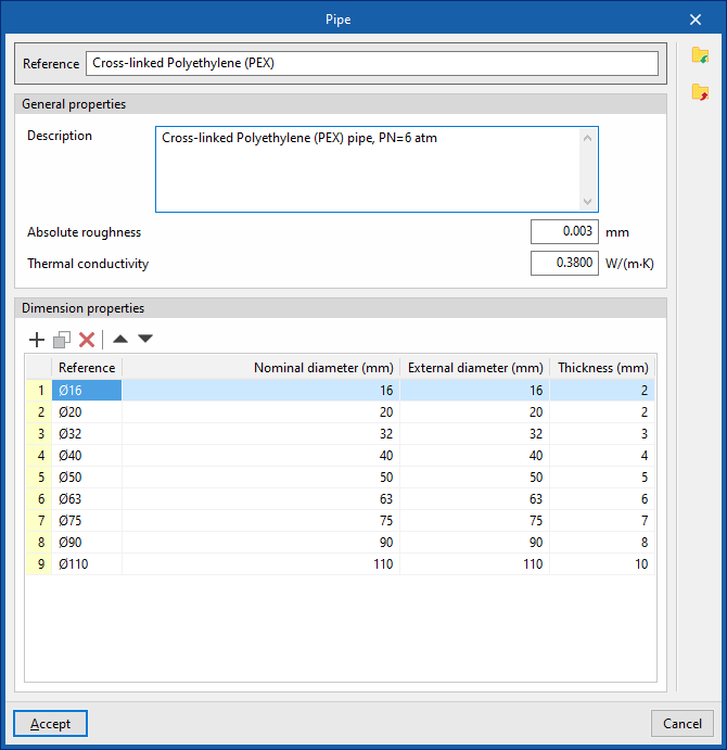
Pipe catalogue
This allows you to define the catalogue of materials available for pipes. The materials defined here can be assigned to pipes created in the "Pipes" section, under "Dimensioning options and checks to be performed" in the "General options". These elements are subsequently added to the model using the options available within the "Hydraulic circuit" block.
When defining each pipe in this section, you must specify the following parameters:
- Reference
Material reference. - General features
- Description
- Absolute roughness
- Thermal conductivity
- Dimensional characteristics (Reference, Nominal diameter, Outer diameter, Wall thickness)
Allows you to enter the dimensional characteristics of each pipe in the series by adding entries to the table.
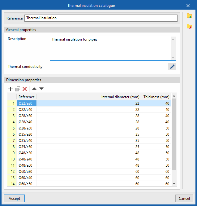
Thermal insulation catalogue
This allows you to define the catalogue of materials available for pipe thermal insulation. The materials defined here can be assigned to pipes created in the "Pipes" section, under "Dimensioning options and checks to be performed" in the "General options". Pipes are subsequently added to the model using the options available within the "Hydraulic circuit" block.
When specifying each type of thermal insulation in this section, the following parameters must be provided:
- Reference
Material reference. - General features
- Description
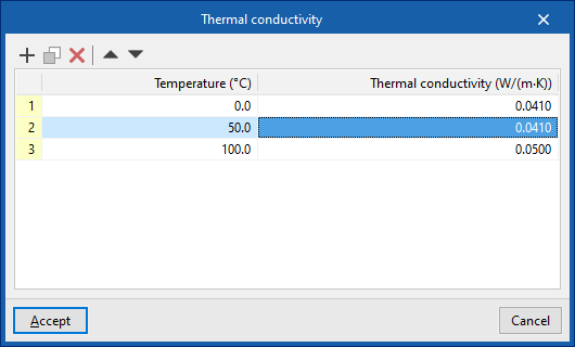
- Thermal conductivity (Temperature, Conductivity)
In this section, you can enter a thermal conductivity value for each temperature value.
- Dimensional characteristics (Reference, Internal diameter, Thickness)
Allows you to enter the dimensional characteristics of each thermal insulation product in the series by adding entries to the table.
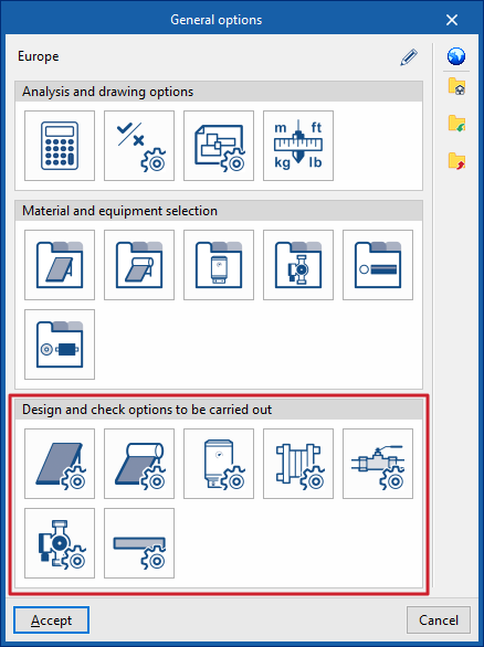
Configuring the design and check options to be carried out during the installation of a solar thermal system
Under the "Installation" tab in the "Solar Systems" section, within the "General options" of the "Project" group on the main toolbar, you can configure the "Sizing options and checks to be performed" for the following components of the solar thermal installation:
- Solar thermal collectors
- Solar thermal collectors with a storage tank
- Batteries
- Heat exchangers
- Accessories
- Pumps
- Pipes
These criteria or options for designs and checks must be defined for each type of element before it is selected and added to the model.
If you use the "Import settings" option, located to the right of the "General options" panel, you can automatically generate this data for different countries and national and international regulations.
The remaining options in the right-hand column allow you to import and export the complete settings from the "General options" panel to files on your hard drive, as well as to select a file containing default values when creating a new project.
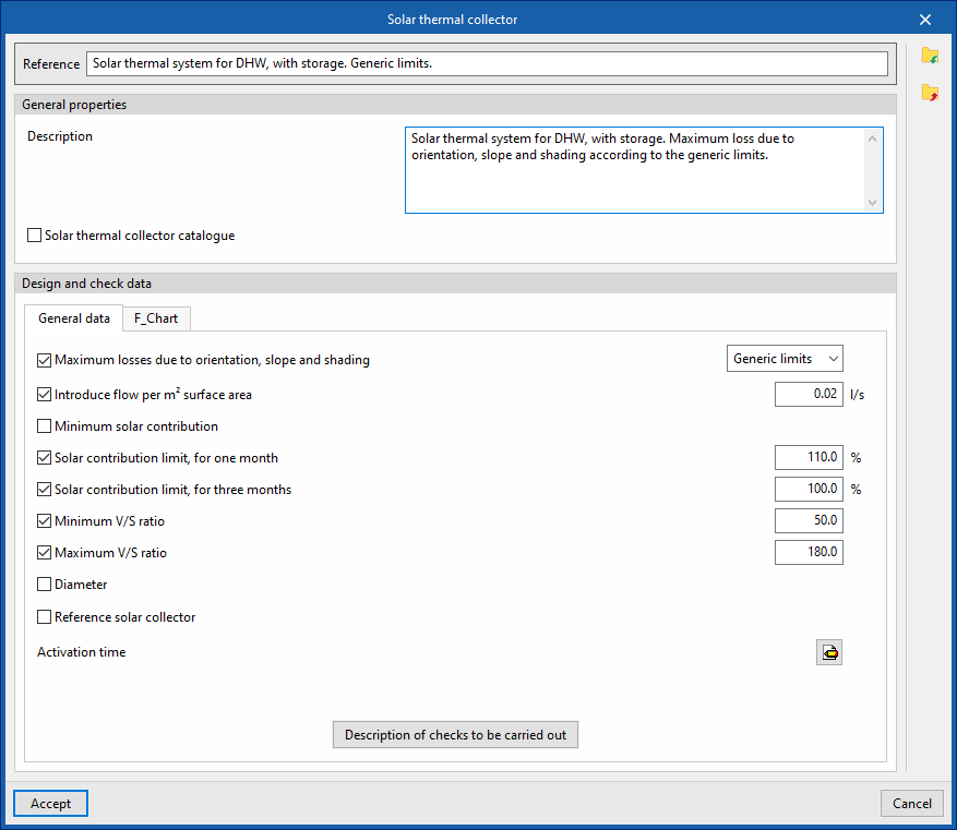
Solar thermal collectors / Solar thermal collectors with storage
This allows you to define the design and check options for solar thermal collectors and solar thermal collectors with storage tanks available in the project. These options are selected when these elements are subsequently added to the model, using the "Solar thermal collector" or "Solar thermal collector with storage tank" options in the "Solar collection" group.
When defining the design and check options for each of these elements, the following parameters must be specified:
- Reference
- General features
- Description
- Solar thermal collector catalogue (optional)
You can link the criterion to one of the materials or items of equipment previously defined in the solar thermal collector catalogue, via the "Solar collector catalogue with storage tank" option, which can be found under "Solar thermal collector catalogue" in the "General options".
- sizing and verification data
- "General Information" tab
- Maximum losses due to orientation, slope and shading (optional)
You can select one of the predefined losses from the "General Checks" section of the "General Options". - Enter flow rate per m2 surface area (optional)
- Minimum solar contribution (optional)
The minimum ratio between the amount of solar energy supplied and the energy demand. - Maximum solar contribution for one month (optional)
The maximum ratio between the amount of solar energy supplied and energy demand over a month. - Maximum solar contribution for three months (optional)
The highest ratio between the amount of solar energy supplied and energy demand over three months. - Minimum V/S ratio (optional)
The minimum required ratio between the storage volume and the catchment area. - Maximum V/S ratio (optional)
The maximum permissible ratio between the storage volume and the catchment area. - Diameter (optional)
- Reference solar thermal collector (optional)
Defining a reference solar thermal collector requires the following data to be entered: Azimuth, Tilt, Effective area per subscriber, η0, a1, a2, IAM. - Activation time
Defined by the number of active hours in each month of the year. - Description of checks to be carried out
Allows you to enter a description of the checks to be carried out on the element. This text will appear in the lists next to each check.- Daily volume
- Maximum solar contribution for one month
- Maximum solar contribution for three months
- V/S ratio
- Loss due to orientation or slope
- Shadow losses
- Total losses
- Maximum losses due to orientation, slope and shading (optional)
- "General Information" tab
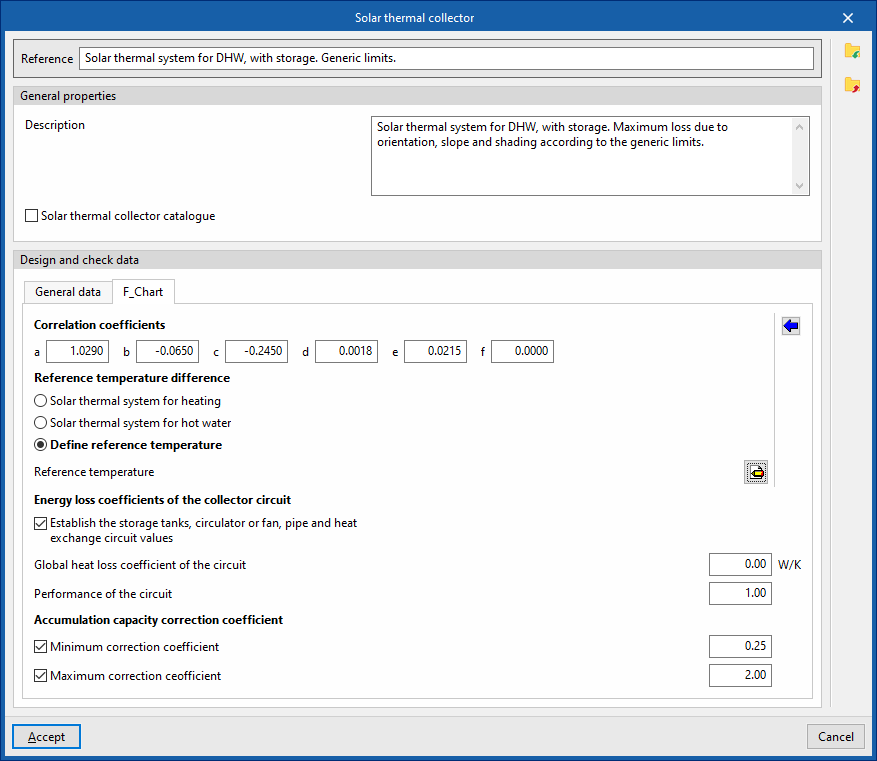
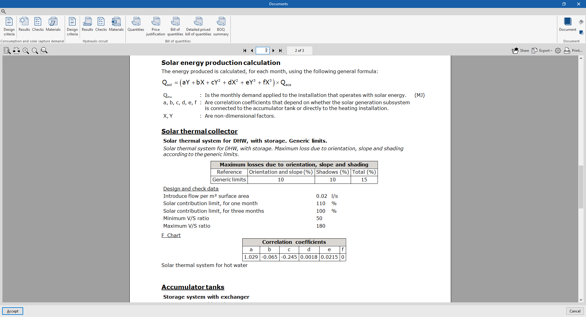
- "F_Chart" tab:
Allows you to set the parameters required to calculate solar collectors using the F-chart method.- Correlation coefficients (a, b, c, d, e, f)
Allows you to modify the coefficients of the expressions used in the method. - Reference temperature difference
The values for the reference temperature difference and the correlation coefficients can be loaded automatically using the wizard on the right, for both a "Direct system" and a "Storage system".- Solar thermal system for heating
- Solar thermal system for hot water
- Define reference temperature
Allows you to enter the "reference temperature" for each month of the year.
- Energy loss coefficients of the collector circuit
- Set the circuit values for the manifolds, circulators or fans, pipes and heat exchangers (optional)
- Global heat loss coefficient of the circuit
- Performance of the circuit
- Set the circuit values for the manifolds, circulators or fans, pipes and heat exchangers (optional)
- Accumulation capacity correction coefficient
- Minimum correction factor (optional)
- Maximum correction factor (optional)
- Correlation coefficients (a, b, c, d, e, f)
Batteries
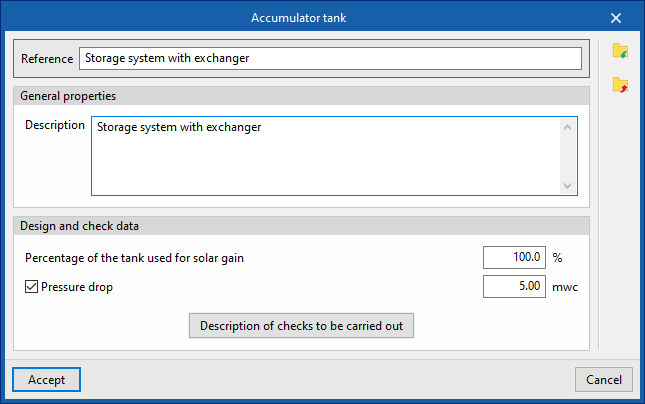
This allows you to define the design and check options for storage tanks available in the project. These options are selected when these elements are subsequently added to the model, using the "Storage tank" option in the "Demand" group.
When configuring these options, you must specify the following parameters:
- Reference
- General features
- Description
- Design and check data
- Percentage of the tank used for solar gain
- Pressure drop (optional)
The pressure drop associated with the tank. - Description of checks to be carried out
Allows you to enter a description of the checks to be carried out on the element. This text will appear in the lists next to each check.- Daily volume
Heat exchangers
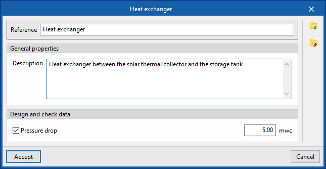
This allows you to define the heat exchanger sizing and verification options available in the project. These options are selected when these elements are subsequently added to the model, using the "Heat exchanger" option in the "Demand" group.
When configuring these options, you must specify the following parameters:
- Reference
- General features
- Description
- Design and check data
- Pressure drop (optional)
The pressure drop associated with the heat exchanger.
- Pressure drop (optional)
Fittings
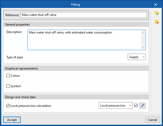
This allows you to define the design and check options for fittings available in the project. These elements can subsequently be added to the model using the "Fitting" option within the "Hydraulic circuit" group.
When configuring these options, you must specify the following parameters:
- Reference
- General features
- Description
- Pipe type (Supply / Return)
- Graphic representation
- Colour (optional)
- Symbol (optional)
- Design and check data
- Local pressure loss calculation (optional)
This allows you to enable the calculation of localised pressure drop in the fitting and define the calculation criteria by selecting one of the available options:- Local pressure loss
- Equivalent length
- Local pressure loss calculation (optional)
Pumps
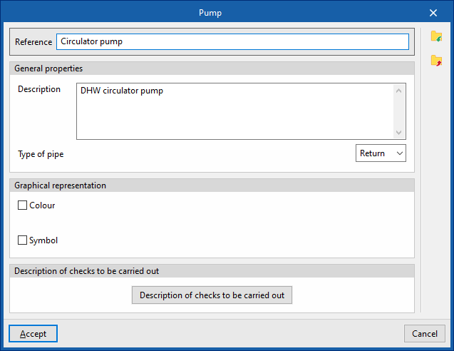
This allows you to define the pump design and check options available in the project. These elements are subsequently added to the model using the "Pump" option in the "Hydraulic circuit" group.
When configuring these options, you must specify the following parameters:
- Reference
- General features
- Description
- Pipe type (Supply / Return)
- Graphic representation
- Colour (optional)
- Symbol (optional)
- Design and check data
- Description of the checks to be carried out
Allows you to enter a description of the checks to be carried out on the element. This text will appear in the reports next to each check.- Increase in pressure
- Description of the checks to be carried out
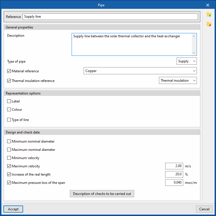
Pipes
This allows you to define the piping design and check the options available in the project. These elements are subsequently added to the model using the options available within the "Hydraulic circuit" group, such as "Pipe".
When configuring these options, you must specify the following parameters:
- Reference
- General features
- Description
- Type of pipe (Supply / Return)
- Material reference
This allows you to select one of the materials listed in the "Pipe catalogue" table, under the "Material and equipment selection" section of the "General options". - Thermal insulation reference
This allows you to select one of the materials listed in the "Thermal insulation catalogue" table, under the "Selection of materials and equipment" section of the "General options".
- Graphic representation
- Tag (optional)
- Reference (optional)
- Diameter (optional)
- Insulation (optional)
- Colour (optional)
- Line type (optional)
- Tag (optional)
- Design and check data
- Minimum nominal diameter (optional)
The minimum permissible nominal diameter of the pipe. - Maximum nominal diameter (optional)
The maximum permissible nominal diameter of the pipe. - Minimum velocity (optional)
Minimum permissible fluid velocity in the section. - Maximum velocity (optional)
Maximum permissible fluid velocity in the section. - Increase of the real length (optional)
Allows you to apply a percentage increase to the actual length of the pipe based on the length entered in the model. - Maximum pressure loss of the span (optional)
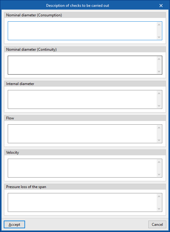
Maximum permissible pressure drop in the pipe section. - Description of the checks to be carried out
Allows you to enter a description of the checks to be carried out on the element. This text will appear in the lists next to each check.- Nominal diameter (Consumption)
- Nominal diameter (Continuity)
- Inner diameter
- Flow rate
- Velocity
- Pressure loss in the span
- Minimum nominal diameter (optional)
Defining the location in the solar thermal installation project
Under the "Installation" tab in the "Solar Systems" section, within the "General options" of the "Project" group on the main toolbar, you will find the option that allows you to specify the location for the solar thermal installation project:

Location
This allows you to specify the project location by entering the following details:
- City
- Description
- Altitude
- Latitude
- Length
- Minimum solar contribution (optional)
Allows you to define a "Minimum solar contribution" value for each "Daily DHW demand" value by adding entries to a table. - Calculation of loss due to orientation and slope obtained from the diagram for latitude 41° north (optional)
- Monthly daily average solar radiation on horizontal surface
This allows you to specify the monthly average daily global solar radiation on a horizontal surface for each month of the year. - Mains cold water temperature
This allows you to set the mains cold water temperature for each month of the year. - External temperature
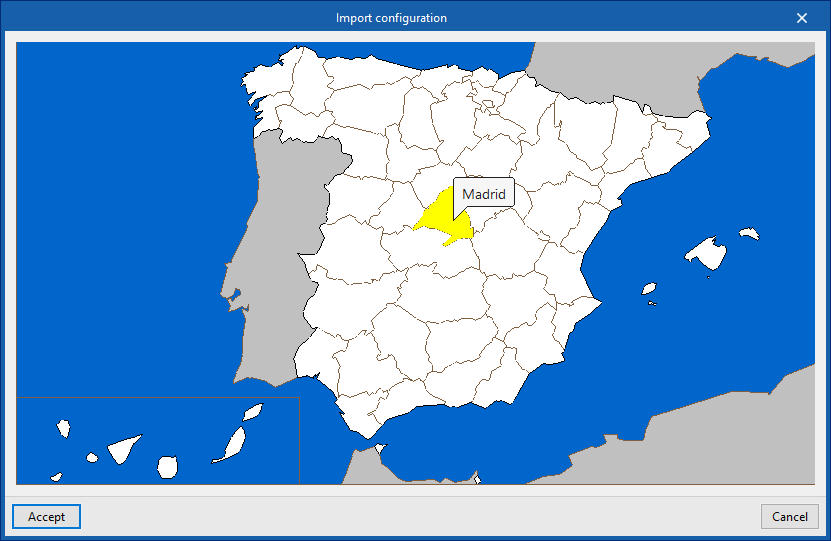
Allows you to set the outdoor temperature for each month of the year.
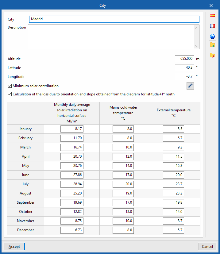
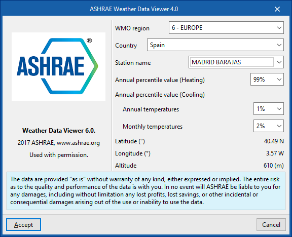
Using the options in the right-hand column, you can import these values from predefined data for different countries or from databases such as ASHRAE Weather Data Viewer 6.0.
Coordination between the water supply and solar thermal energy systems
Within the "Installation" tab of the "Water Systems" section, the "Project" button in the bottom-right corner of the group of the same name on the main toolbar contains the option that allows you to coordinate DHW production units, storage tanks and heat exchangers in water supply and solar thermal energy systems:

This feature is equivalent to the one found under the "Installation" tab in the "Solar Systems" section, within the "Project" group on the main toolbar:

On the "Water Systems" tab, clicking on the option opens a window displaying three tabs:
- DHW Production - Accumulator tanks
- Heat exchangers
- Usage - Downloads
On the "Solar Systems" tab, the following tabs are available:
- DHW Production - Storage Tanks
- Heat exchangers
Coordination between consumption and discharge is carried out in the "DHW Production – Storage Tanks" and "Heat Exchangers" tabs. Both tabs operate in a similar way.
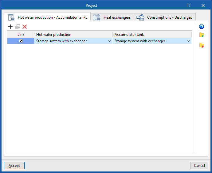
"Hot water production – Accumulator tanks" tab
This tab allows you to link DHW production units listed under the "Water Systems" tab with storage tanks listed under the "Solar Systems" tab.
The tab displays a table with three columns:
- Link
- Hot water production
- Accumulator tank
The program allows you to specify the storage tank associated with each DHW production unit by selecting it in each entry of the table. Thus, when a DHW production unit is entered in the "Water Systems" tab, the associated storage tank is automatically entered in the "Solar Systems" tab; and conversely, when a storage tank is entered in the "Solar Systems" tab, the associated DHW production unit is automatically entered in the "Water Systems" tab.
If the "Link" checkbox is ticked, the associated DHW production unit and accumulator tank will remain linked for editing operations such as moving them. Thus, when the DHW production unit is moved, the accumulator will also be moved.
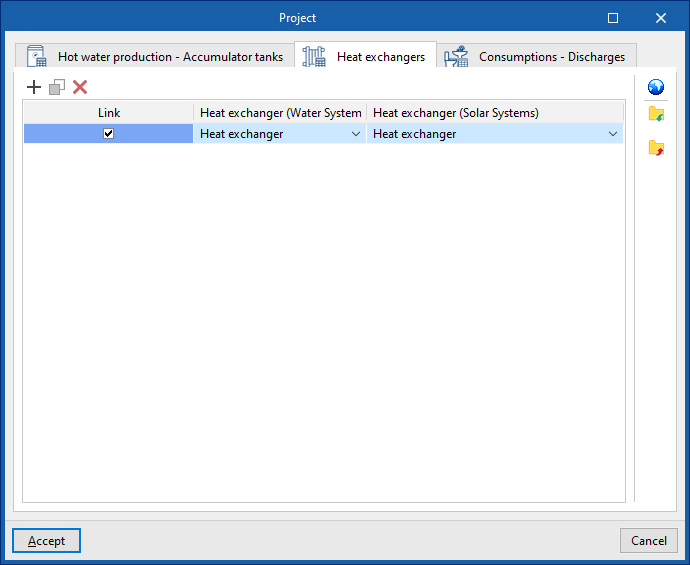
"Heat exchangers" tab
This tab allows you to link heat exchangers in the "Water Systems" tab with heat exchangers in the "Solar Systems" tab.
The tab displays a table with three columns:
- Link
- Heat exchanger (Water Systems)
- Heat exchanger (Solar Systems)
The program allows you to define the heat exchanger in the "Solar Systems" tab associated with each heat exchanger in the "Water Systems" tab by selecting it in each table entry. In this way, when a heat exchanger is entered in the "Water Systems" tab, the associated heat exchanger is automatically entered in the "Solar Systems" tab; and vice versa, when a heat exchanger is entered in the "Solar Systems" tab, the associated heat exchanger is automatically entered in the "Water Systems" tab.
If the "Link" checkbox is ticked, the heat exchangers will remain linked for editing operations such as moving them. Thus, when the heat exchanger in the "Water Systems" tab is moved, the heat exchanger in the "Solar Systems" tab will also be moved.
Importing local settings
From either of the two windows, you can use the "Settings" option in the top-right corner to automatically load device settings for different countries and regions.
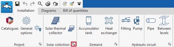
Inserting collectors in a solar thermal system
Under the "Installation" tab in the "Solar Systems" section, within the "Solar Collection" group on the main toolbar, you will find the options for adding collectors to the solar thermal energy system:

Solar thermal collector / Solar thermal collector with storage tank
These two options allow for the installation of solar thermal collectors (without integrated storage) or solar thermal collectors with storage tanks (including compact systems or thermosiphon systems), respectively.
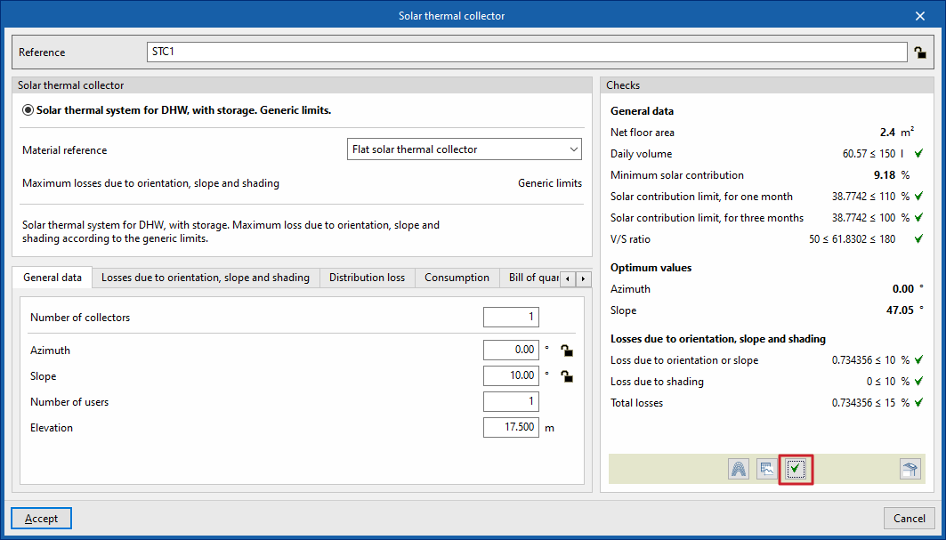
When adding or editing a solar thermal collector, you can configure the following parameters. Some of these appear only if the "Simplified entry" option under "Design options" in "General options" is disabled:
- Reference
The reference for the element. This value can be locked or unlocked. If it is unlocked, the program will create or modify the reference when updating results. - Solar thermal collector
This allows you to select the criteria or options for sizing and checking solar thermal collectors. These options can be created and edited under "Design and check options" in "General options", within the "Project" section. - Material reference
This allows you to select the reference for the material or equipment associated with the solar thermal collectors from the relevant catalogues in the "Selection of materials and equipment" section, under "General options", within the "Project" group. - Maximum losses due to orientation, tilt and shading
Displays the maximum losses due to orientation, tilt and shading associated with the solar thermal collector selected above.
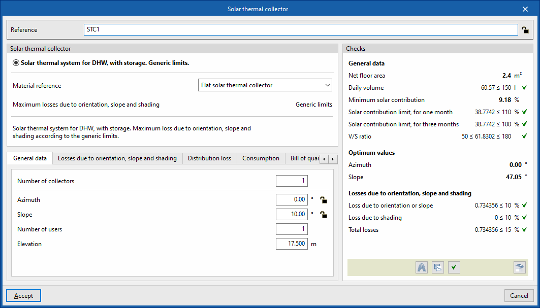
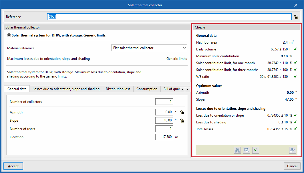
- "General data" tab:
Allows you to define general details of the element entered, such as the number of collectors, their spatial layout, the number of subscribers and their elevation.- Number of collectors
- Azimuth (Lock/Unlock)
The angle of the sensor relative to the south. This value is taken from the element’s definition in the model. - Slope (Lock/Unlock)
- Number of users
- Elevation
Elevation of the sensor insertion point.
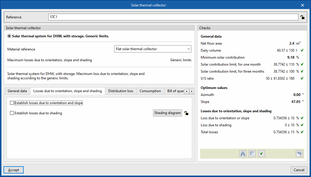
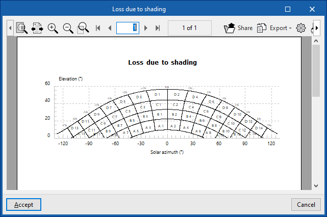
- "Losses due to orientation, slope and shading" tab
- Establish losses due to orientation and slope (optional)
- Establish losses due to shading (optional)
- Shading diagram (Lock/Unlock)
The shading diagram over the sensors is generated automatically during the calculation.
- Shading diagram (Lock/Unlock)
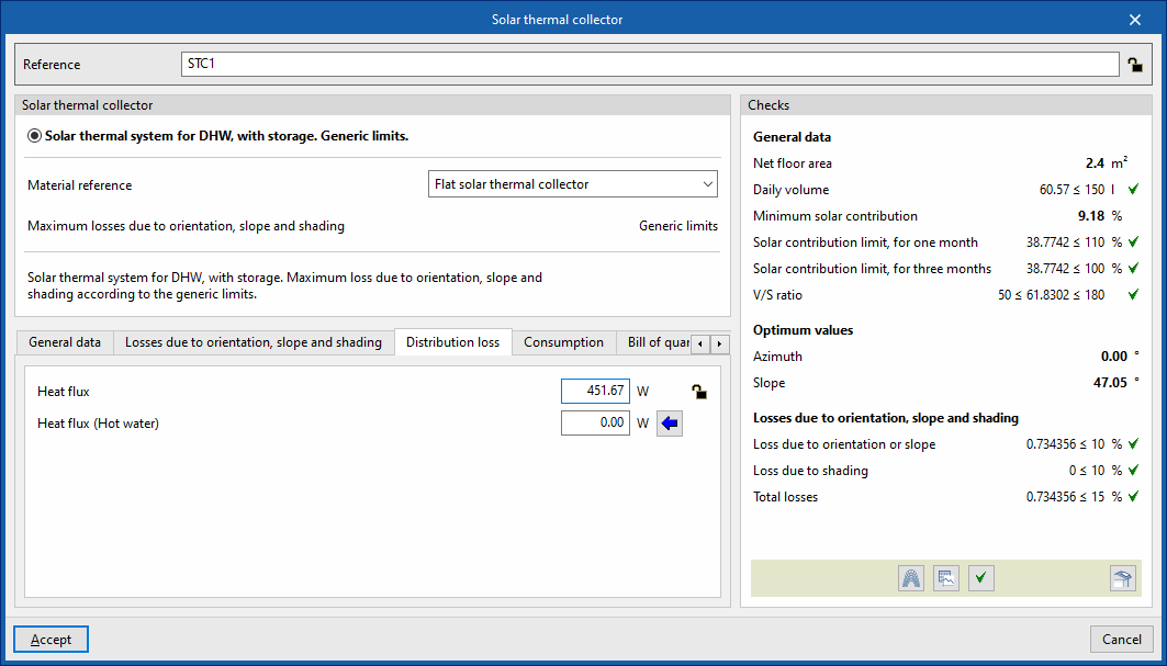
- "Distribution loss" tab:
Allows you to define the distribution losses associated with the collector.- Heat flux (Lock/Unlock)
- Heat flux (DHW)
The wizard on the right allows you to calculate this value using the following data:- Equivalent length
- Temperature
- Inner diameter
- Thickness
- Thermal conductivity
- Insulation (optional)
- Thickness of the thermal insulation
- Thermal conductivity of insulation
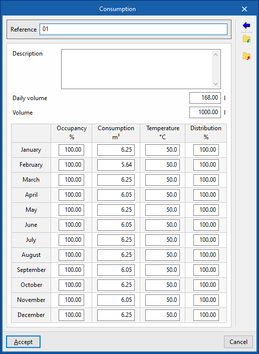
- "Consumption" tab (Lock/Unlock)
Allows you to manage the consumption data associated with the sensor by editing entries in a table. When entering consumption data, you must provide the following information:- Reference
- Description
- Daily volume
- Volume
- Occupancy (%) / Consumption (m³) / Temperature (°C) / Distribution (%)
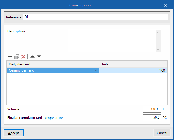
These figures are calculated for each month. - Usage
Using this button, located on the right-hand side of the panel, you can load this data using the following values:- Reference
- Description
- Daily demand, per unit / Units
The values for "Daily demand, per unit" can be configured under "Demand criteria", within "Design options", and, in turn, under "General options". In addition, you must enter the number of "Units" associated with the equipment. - Volume
- Final storage tank temperature
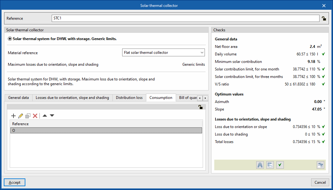
- "Bill of quantities" tab:
Allows you to control the generation of the element's bill of quantities using filters.- Solar thermal collector
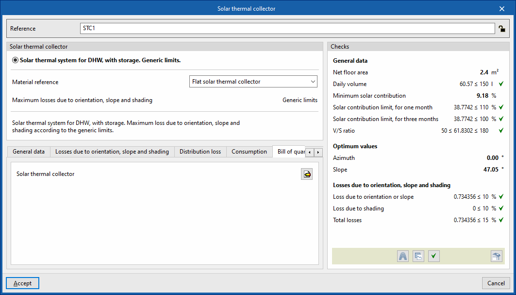
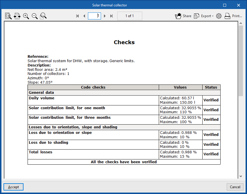
- Checks
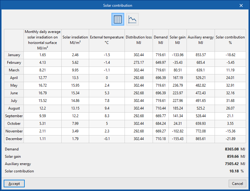
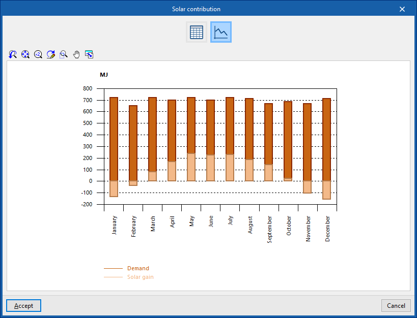
Allows you to view and list the checks performed on the element. The tools in the bottom centre allow you to view graphs, tables and design reports. In addition, the tool in the bottom right-hand corner allows you to perform a partial design of the element using the data entered in the panel.- Shadow losses
- Solar contribution
- View calculation results (formulae, checks, etc.).
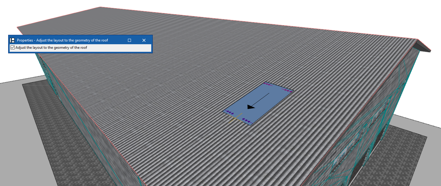
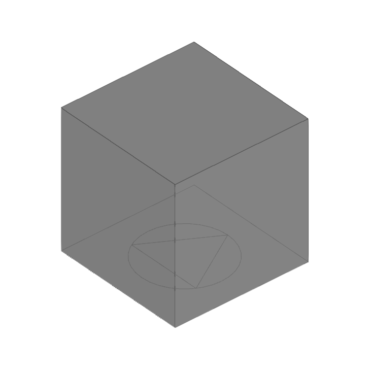
Positioning of the solar thermal collector in the "Work area"
When placing the solar thermal collector in the workspace, the program allows you to tick the box labelled "Adjust layout to roof geometry". If this option is selected, when you click on a sloped plane, the collector will adopt the "Slope" value based on the roof data from the model.
| Note: |
|---|
| The button in the bottom-right corner of the "Solar collection" group allows you to access the configuration options for the elements in this group. These options are the same as those available under "Design and check options" in "General options", within the "Project" group. |
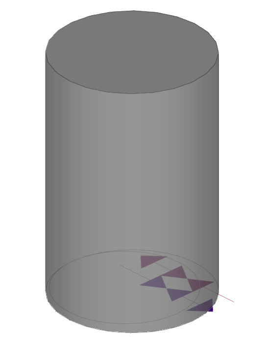
Inserting storage tanks and heat exchangers in a solar thermal system
Under the "Installation" tab in the "Solar Systems" section, within the "Demand" section of the main toolbar, you will find the options for adding storage tanks and heat exchangers to the solar thermal system:

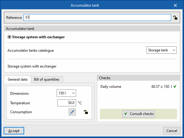
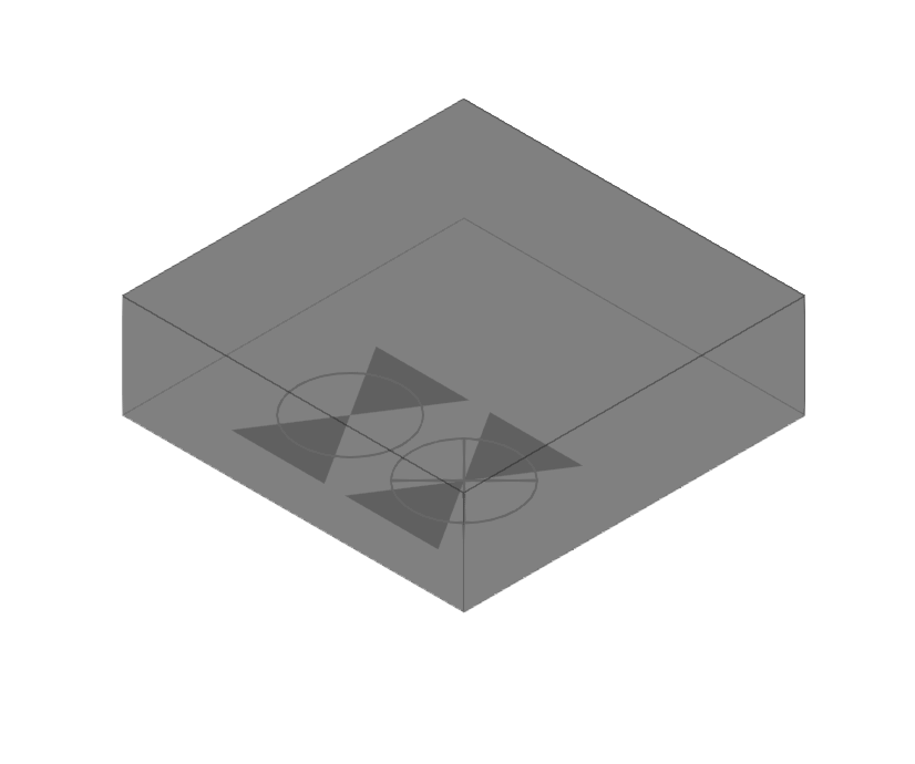
Accumulator tank
This option allows you to include storage tanks and combined storage tanks (storage systems with an integrated heat exchanger) in the model.
When entering or editing an accumulator tank, you can configure the following parameters. Some parameters only appear if the "Simplified entry" option under "Design options" in "General options" is disabled:
- Reference
The reference for the element. This value can be locked or unlocked. If it is unlocked, the program will create or modify the reference when updating results. - Storage tank
Allows you to select the criteria or options for designing and checking storage tanks. These options can be created and edited under "Design and check options" in "General options", within the "Project" section. - Accumulator tank catalogue
This allows you to select the accumulator tank catalogue from those defined in the "Material and equipment selection" section, under "General options", within the "Project" group.
- "General data" tab
Allows you to define general details for the entered item:- Dimensions
- Temperature
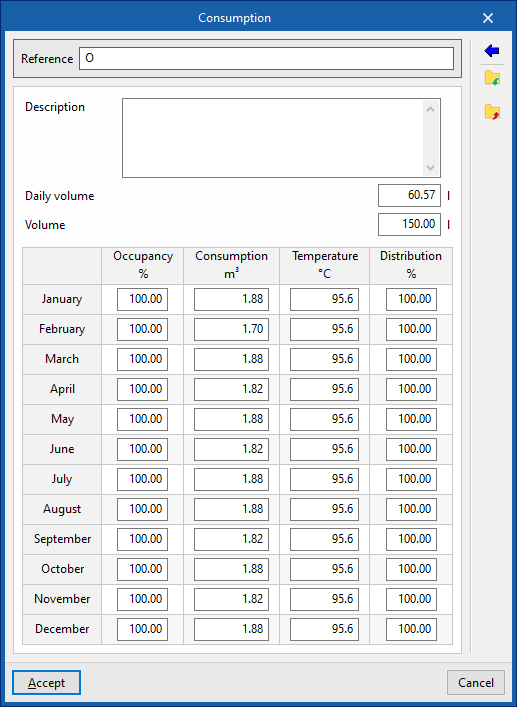
- "Consumption" tab (Lock/Unlock)
Allows you to manage consumption data associated with the battery by editing entries in a table. When entering consumption data, you must provide the following information:- Reference
- Description
- Daily volume
- Volume
- Occupancy (%) / Consumption (m³) / Temperature (°C) / Distribution (%)
These figures are calculated for each month. - Usage
Using this button, located on the right-hand side of the panel, you can load this data using the following values:- Reference
- Description
- Daily demand, per unit / Units
The values for "Daily demand, per unit" can be configured under "Demand criteria", within "Design options", and, in turn, under "General options". In addition, you must enter the number of "Units" associated with the equipment.

- "Bill of quantities" tab:
Allows you to control the generation of the item's bill of quantities using filters.- Accumulator tank
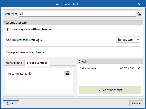
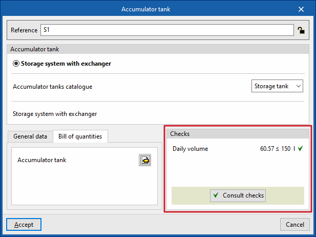
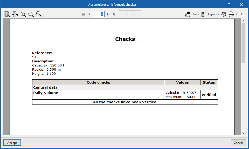
- Checks
Allows you to view the checks carried out on the element. The tool at the bottom centre allows you to view a report detailing the checks carried out:- Consult checks
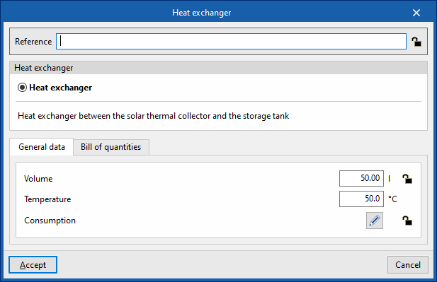
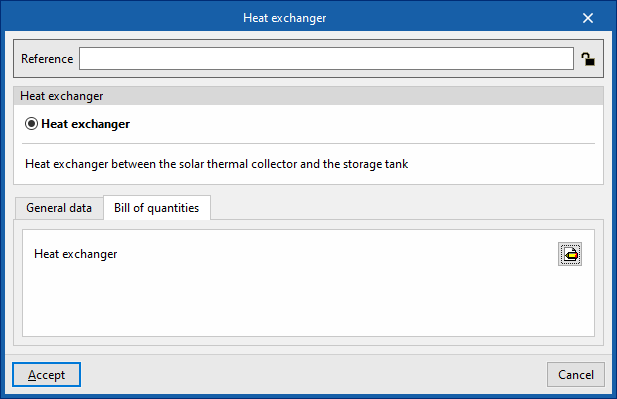
Heat exchanger
This option allows you to include heat exchangers in the model.
When adding or editing an exchanger, you can configure the following parameters. Some parameters only appear if the "Simplified entry" option under "Design options" in "General options" is disabled:
- Reference
The reference for the element. This value can be locked or unlocked. If it is unlocked, the program will create or modify the reference when updating results. - Heat exchanger
Allows you to select the criteria or options for the sizing and verification of heat exchangers. These options can be created and edited under "Design and check options" in "General options", within the "Project" section.
- "General data" tab
Allows you to define general details for the entered element:- Volume (Lock/Unlock)
- Temperature
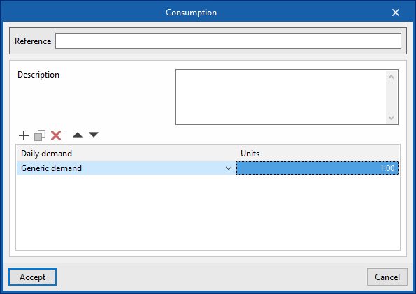
- "Consumption" tab (Lock/Unlock)
Allows you to manage the consumption data associated with the heat exchanger by editing entries in a table. When entering consumption data, you must provide the following information:- Reference
- Description
- Daily volume
- Volume
- Occupancy (%) / Consumption (m³) / Temperature (°C) / Distribution (%)
These figures are calculated for each month. - Usage
Using this button, located on the right-hand side of the panel, you can load this data using the following values:- Reference
- Description
- Daily demand, per unit / Units
The values for "Daily demand, per unit" can be configured under "Demand criteria", within "Calculation options", and, in turn, under "General options". In addition, you must enter the number of "Units" associated with the equipment.

- "Bill of quantities" tab:
Allows you to control the generation of the item's bill of quantities using filters.- Heat exchanger
| Note: |
|---|
| The button in the bottom-right corner of the "Load" group provides access to the options for defining the elements in this group. These options are the same as those available under "Design and check options" in "General options", within the "Project" group. |
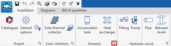
Inserting fittings and pumps in a solar thermal system
Under the "Installation" tab in the "Solar Systems" section, within the "Hydraulic circuit" group on the main toolbar, you will find the options for adding fittings and pumps to the solar thermal system:

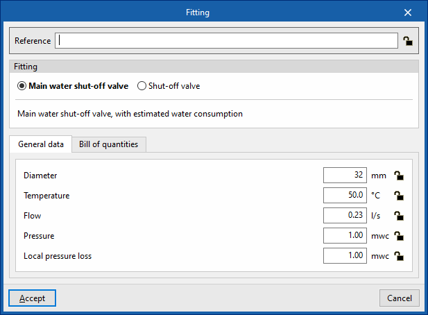
Fitting
This option allows you to add fittings (such as supply valves or shut-off valves) to the model.
When entering or editing a fitting, you can configure the following parameters. Some parameters only appear if the "Simplified entry" option under "Design options" in "General options" is disabled:
- Reference
The reference for the element. This value can be locked or unlocked. If it is unlocked, the program will create or modify the reference when updating results. - Fitting
Allows you to select the criteria or options for dimensioning and checking accessories. These options can be created and edited under "Design and check options" in "General options", within the "Project" section.

- "General data" tab: Allows you to define general details for the entered item:
- Diameter (Lock/Unlock)
- Temperature (Lock/Unlock)
- Flow (Lock/Unlock)
- Press (Lock/Unlock)
- Localised pressure drop (Lock/Unlock)
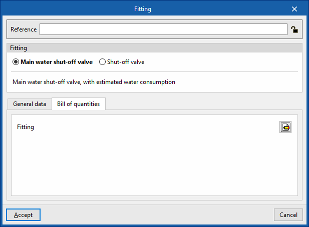
- "Bill of quantities" tab:
Allows you to control the generation of the element's bill of quantities using filters.- Fitting
Pump
This option allows you to include circulation pumps in the model.
When adding or editing a pump, you can configure the following parameters. Some parameters only appear if the "Simplified entry" option under "Design options" in "General options" is disabled:
- Reference
The reference for the element. This value can be locked or unlocked. If it is unlocked, the program will create or modify the reference when updating results. - Pump
Allows you to select the criteria or options for designing and checking pumps. These options can be created and edited under "Design and check options" in "General options", within the "Project" section.
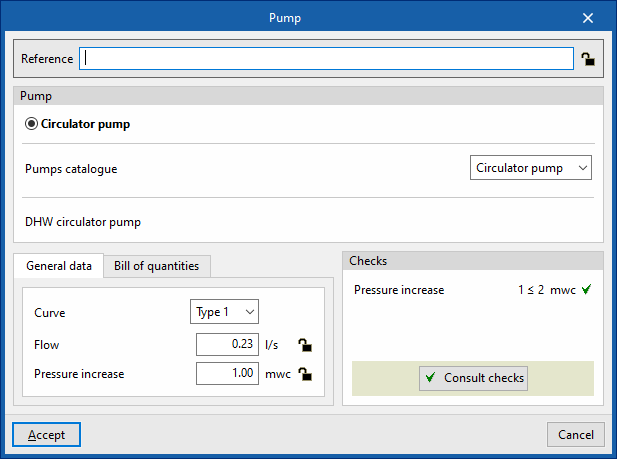
- "General data" tab
Allows you to define general details for the entered item:- Curve
- Flow (Lock/Unlock)
- Pressure increase (Lock/Unlock)
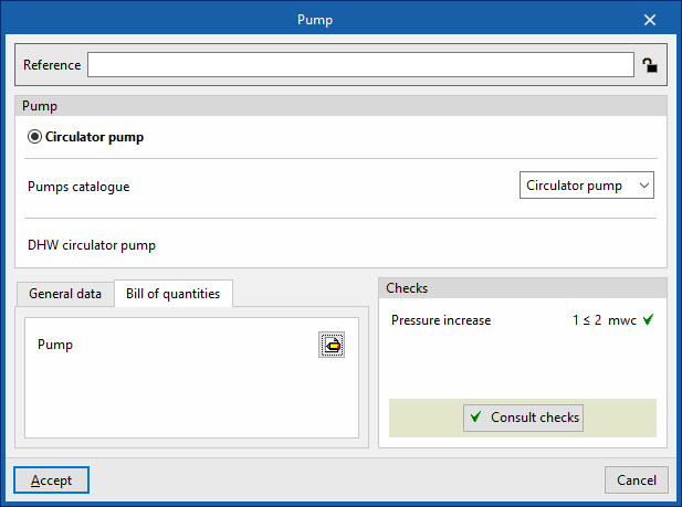
- "Bill of quantities" tab:
Allows you to control the generation of the element's bill of quantities using filters.- Pump
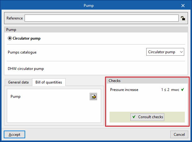
- Checks
Allows you to view the checks carried out on the element. The tool at the bottom centre allows you to view a report detailing the checks carried out:- Consult checks
| Note: |
|---|
| The button in the bottom-right corner of the "Hydraulic circuit" group provides access to the options for defining the elements in this group. These options are the same as those available under "Design and check options" in "General options", within the "Project" option. |
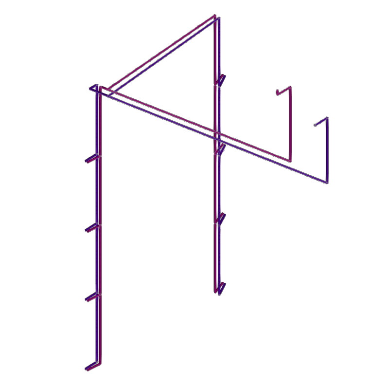
Installation of pipework in a solar thermal system
Under the "Installation" tab in the "Solar Systems" section, within the "Hydraulic circuit" group on the main toolbar, you will find the options for adding the pipework for the solar thermal system:

Pipes
It allows you to add pipes to the solar thermal system by freely defining their geometry in any position.
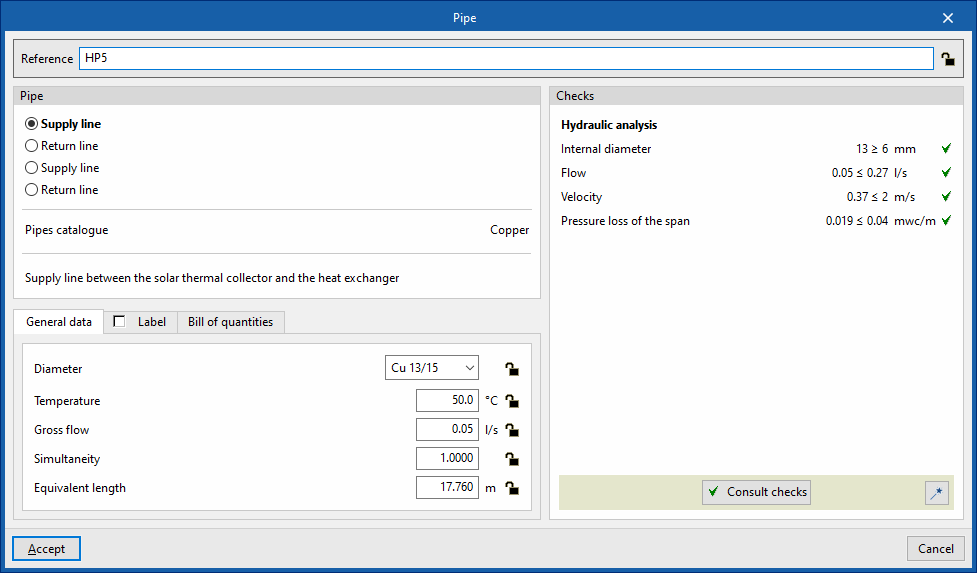
When inserting or editing a pipe, you can configure the following parameters. Some parameters only appear if the "Simplified entry" option is disabled; this option can be accessed via "Design options" under "General options":
- Reference
The reference for the element. This value can be locked or unlocked. If it is unlocked, the program will create or modify the reference when updating results. - Pipe
Allows you to select the pipe type. These types can be created and edited in the "Project" group, under the "Design and check options" section of the "General options". The program also displays the "Pipe catalogue" associated with the type.
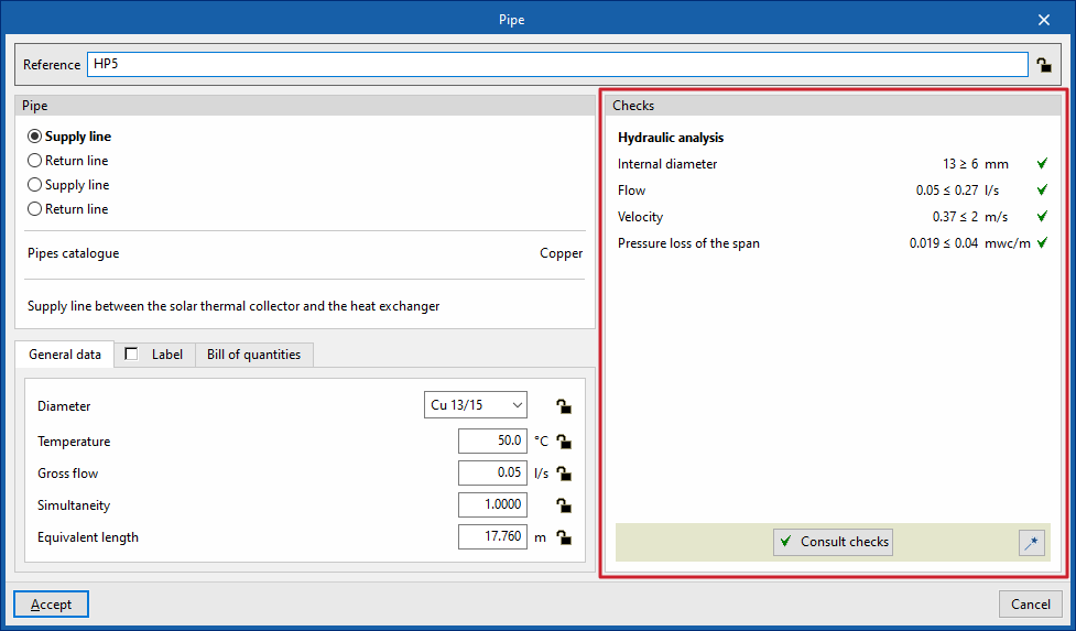
- "General data" tab
This allows you to define the general details of the item. Some of these values can be locked or unlocked. If a value is locked, it will not be modified when the results are updated, but will remain unchanged.- Diameter (Lock/Unlock)
Allows you to select the pipe diameter from those available in the series. - Temperature (Lock/Unlock)
- Gross flow (Lock/Unlock)
- Simultaneity (Lock/Unlock)
- Equivalent length (Lock/Unlock)
- Diameter (Lock/Unlock)
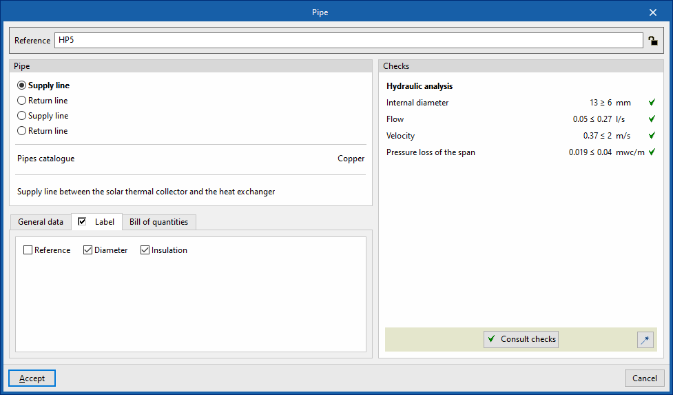
- "Label" tab (optional)
Allows you to manage the information displayed on the element's label.- Reference
- Diameter
- Insulation
- "Bill of quantities" tab:
Allows you to control the generation of the element's bill of quantities using filters.- Pipe
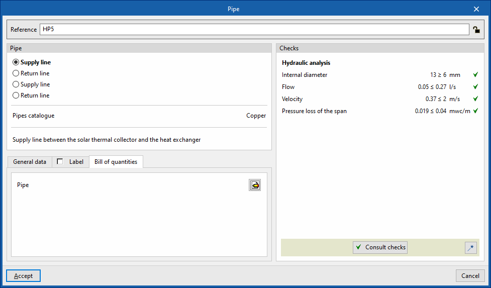
- Checks
Allows you to view and list the checks performed on the element. These checks can be enabled, edited or disabled via "Design and check options" in the "General options" section of the "Project" group.- Design
This tool, accessible via the button in the bottom-right corner of the pipe editing panel, allows you to automatically dimension the pipe so that it meets the defined checks.
- Design
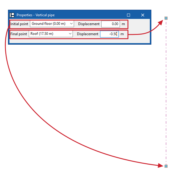
Pipe between floors
The "Between levels" option allows you to insert pipes for the solar thermal system by defining their geometry between levels.
When you click on this option, the program allows you to define the pipe’s characteristics using an editing panel identical to the one that appears when you use the “Pipe” option.
Next, in the "Properties – Vertical Pipe" dialogue box, you define the levels associated with the pipe’s "Initial point" and "Final point", along with a "Displacement" for each of the specified levels, expressed as positive or negative values. The pipe’s position on the plan view is marked by placing the cursor on a point within the workspace.
| Note: |
|---|
| The button in the bottom-right corner of the "Hydraulic circuit" group allows you to access the settings for the elements in this group. These settings are equivalent to those available under the "Design and check options" section in the "General options" of the "Project" group. |
Editing tools
In the "Edit" section of the main toolbar on the "Installation" tab, within the "Water Systems", "Sanitary Systems" or "Solar Systems" tabs, you will find the following tools:


Edit
The options in this menu allow the following editing operations to be carried out on the elements of the system entered in the model:
| Edit | Edits the parametric properties of the selected element in the model. | |
| Delete | Deletes a previously entered element. | |
| Move element | Moves an element or a node of an element. | |
| Move a group of elements | Moves a group of elements. | |
| Rotate element | Rotates an element about the "x", "y" or "z" axis. | |
| Rotate a group of elements | Rotates a group of elements. | |
| Copy | Creates a copy of one or more elements. | |
| Assign | Assigns the parametric properties of the selected element to other elements. | |
| Symmetry (copy) | Copies a selection of elements with symmetry with respect to a vertical plane defined by two points. | |
| Symmetry (move) | Moves a selection of elements with symmetry about a vertical plane defined by two points. | |
| Copy onto another floor plan | Creates a copy of the selected elements in the desired floor plans. This feature is only available on floor plans. | |
| Add points | Adds intermediate points along the pipes. The pipe remains a single, undivided element. | |
| Delete points | Deletes intermediate points on pipes. The pipe remains as a single, undivided element. | |
| Join | Joins two pipes into a single pipe, creating a connecting section if necessary. The resulting pipe takes on the properties of the first pipe selected when this option is used. | |
| Split | Splits a pipe in two at the selected point. | |
| Measure lengths on plan | Measures lengths and angles between points defined in the model. If a closed outline is selected, it also indicates the area. | |
| Projection | Switches to the plan projection (XY plane) in the work area. |
Label
The options in this menu allow you to perform the following operations on the tags of the elements:
| Move tag in 2D mode | Moves the selected tag on the element's floor plan. | |
| Move tag in 3D mode | Moves the selected tag in the 3D space. | |
| Move tag to the initial point | Returns the tag of the selected element to the initial point. | |
| Show/hide tag | Shows or hides the line linking the tag to the selected element it refers to. | |
| Place or remove the reference line of the tag | Shows or hides the line linking the tag to the selected element it refers to. | |
Rotate tag | Rotates the tag over its position. | |
| Tag | Edits the composition of the labels of different categories of elements and the size of the text. |
Notes
The options in this menu allow you to insert the following drawing elements into a floor plan:
| Note: |
|---|
| You can enable or disable the display of these elements using the "Editing resources" option in the "Layer settings" panel, which is located by default on the left-hand side of the main interface. |
Elevation | Enters an elevation between two selected points, indicating the line colour, line thickness, and text size. | |
| Line | Inserts a line between two selected points, indicating its colour and thickness. | |
| Text | Enter a text and a reference line, indicating its colour, the line thickness and the text size. | |
| Text box | Enters a left-aligned, right-aligned or centred text box, indicating the colour and size of the text, the properties of the frame and the background fill. | |
| Arc | Enters an arc and, optionally, its radius, indicating the line colour, line thickness and text size. | |
| Circle | Enters a circle and its radius or diameter, optionally, indicating the line colour, line thickness, and text size. | |
| Rectangle | Enters a rectangle and, optionally, its area, indicating the line colour, line thickness and text size. | |
| Area | Enters a dotted polygon and, optionally, its area, indicating the line colour, line thickness, and text size. | |
| Polyline | Inserts a polyline by points, indicating its colour and thickness. | |
| Edit | Edits the properties of the selected drawing resource. | |
| Move | Moves the selected drawing resource or parts of it. | |
| Copy | Creates a copy of one or more drawing resources. | |
| Assign | Assigns the properties of one drawing resource to others. When you select a drawing resource, any resources with the same properties are highlighted in orange. | |
| Move a group of elements | Moves a group of elements. | |
| Rotate a group of elements | Rotates a group of elements. | |
| Symmetry (move) | Moves a selection of elements with symmetry about a vertical plane defined by two points. | |
| Symmetry (copy) | Copies a selection of elements with symmetry with respect to a vertical plane defined by two points. | |
| Delete | Deletes a previously entered element. |
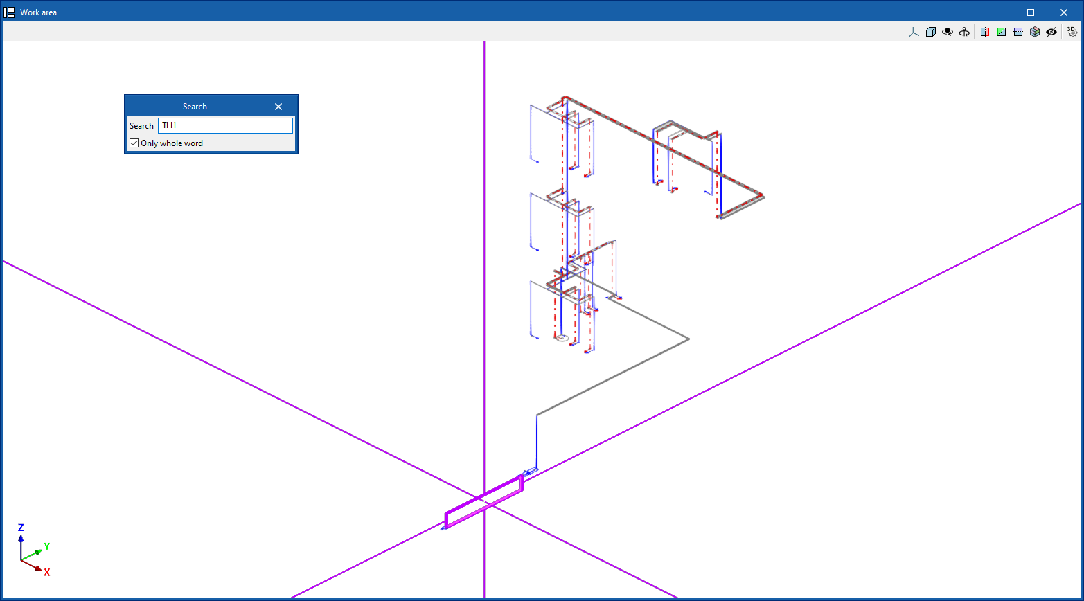
Search
Searches for an element by entering a text with its full reference or part of its reference.
- Only whole word (optional)
If this box is checked, only the elements that match the entered text in full will be searched for.
When doing this, the program locates the element in the model by means of magenta lines in the main directions of the space and an enveloping volume of the same colour.
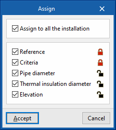
Lock
This option allows you to lock or unlock various definition parameters for model elements so that the program keeps them unchanged when updating results.
This can be done for the selected items in the workspace or, if the following box is ticked, for all items in the installation:
- Apply to the entire installation (optional)
The settings available for locking or unlocking are as follows:
- Reference (optional)
- Criteria (optional)
- Pipe diameter (optional)
- Thermal insulation diameter (optional) (under the "Water Systems" and "Solar Systems" tabs)
- Elevation (optional)
The icon on the right allows you to choose whether to lock or unlock each of the selected settings.
| Nota: |
|---|
| These settings can also be locked or unlocked in the edit panel for each element. |
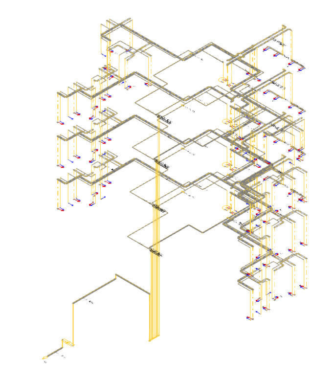
Viewing locked items
The "View locked items" option in the "Layer configuration" panel on the left-hand side highlights model elements in the workspace in yellow if any of the parameters mentioned in the previous option are locked, making them easier to locate.
Bill of quantities
The "Bill of quantities" option opens a menu containing the following tools:
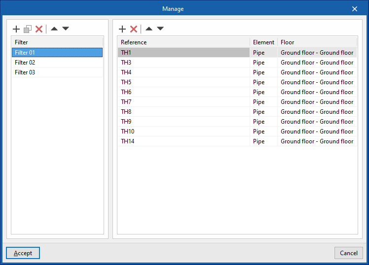
- Filter
Opens a filter manager where you can create filters on the left-hand side and assign them to the desired system components on the right-hand side. - Add
Creates a filter and applies it to the selected items in the workspace. - Delete
Removes the filter assignment from the selected items in the workspace. If the filter assignment is removed from all items, the filter is deleted. - Edit
Edit the filter settings for the selected item in the workspace.
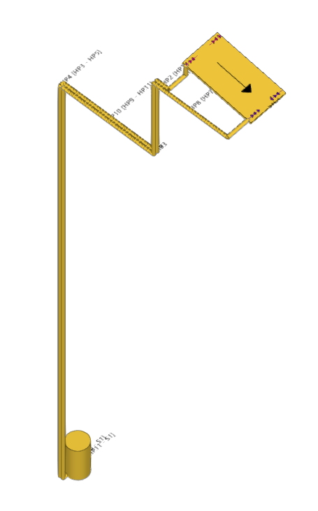
Displaying elements with filters applied
The "Show filters" option in the "Layer settings" panel on the left-hand side displays the model elements, colour-coding them according to the filter to which they are assigned.
| Note: |
|---|
| Filters can also be created and assigned in the edit panel for each element. Filters created and assigned to elements allow for greater control over the bill of quantities generation process. |
Layers
In the "Edit" section, the program offers the following two controls relating to the model’s layers.
The first button allows you to "Update layer settings based on the elements entered in the model". This option is equivalent to the one available in the "Layer settings" panel on the left-hand sidebar.
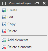
The second button can be used to create and manage "Customised layers". Clicking this button opens a menu with the following options:
- Create
Creates a new custom layer by entering a "Reference". - Edit
Edits the "Reference" of the currently selected custom layer. - Copy
Duplicates the currently selected custom layer. - Delete
Deletes the currently selected custom layer. - Add elements
Selects elements from the model and assigns them to the custom layer selected in the pop-up window’s drop-down menu. To facilitate this operation, you must first select a category of elements in which those elements are visible. - Delete elements
Deletes the assignment of the selected elements from the model to the custom layer selected in the layer list.
You can select, configure, hide and/or control the display of "Customised layers" from the relevant section of the "Layer settings" panel in the left-hand sidebar.
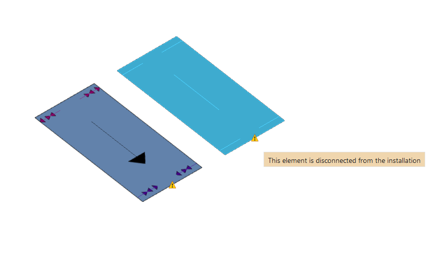
Check
Keeping this option activated highlights the elements in the system where a warning or error has occurred in relation to their insertion or editing by means of an incident system, as in the case of disconnected elements, when they were inserted in the model. The descriptive message of said warning or error is displayed by hovering the cursor over each warning or error.
Graphical analysis of the results of the water supply system
In the "Installation" tab of the "Water Systems" tab, in the "Calculation" group of the main toolbar, there are options for graphically analysing the calculation results of the water supply system:

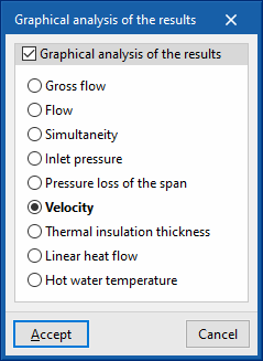
Viewing the graphical analysis of results
This first option is used to select the magnitude involved in the hydraulic analysis of the system to be analysed from among those available. In the "Work area", the program draws the analysis results of the calculation of the elements in the water supply system using a colour scale, making it easier to analyse them.
The magnitudes available in the graphical analysis of results are as follows:
- Gross flow
- Flow
- Simultaneity
- Inlet pressure
- Pressure loss of the span
- Velocity
- Thermal insulation thickness
- Linear heat flow
- Hot water temperature
To update the results information, the model must be re-analysed.
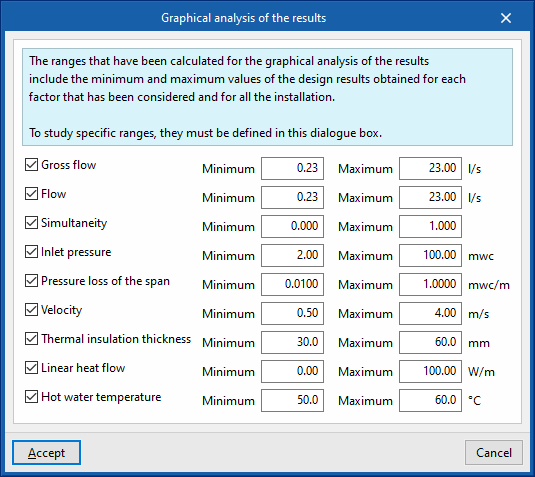
Editing the graphical analysis of results
In the graphical analysis of results, the program displays the minimum and maximum values obtained in the analysis for each magnitude in the whole system by default. However, in the dialogue box that opens with this second option, the colour scale can be adjusted by specifically entering the minimum and maximum values for each of the following magnitudes:
- Gross flow (Minimum, Maximum)
- Flow (Minimum, Maximum)
- Simultaneity (Minimum, Maximum)
- Inlet pressure (Minimum, Maximum)
- Pressure loss of the span (Minimum, Maximum)
- Velocity (Minimum, Maximum)
- Thermal insulation thickness (Minimum, Maximum)
- Linear heat flow (Minimum, Maximum)
- Hot water temperature (Minimum, Maximum)
Results output for solar thermal system
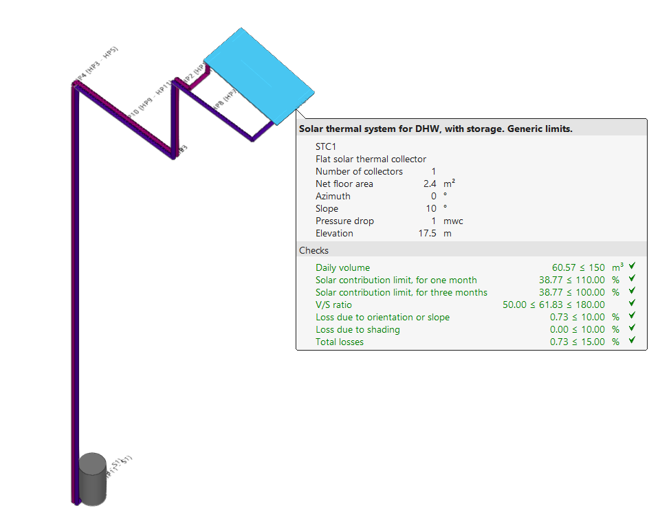
View results on screen
After the analysis, the program displays the results in the tooltip or information text that appears when the cursor is placed on an element in the system, as well as the compliance of the checks carried out on it. To do this, the "Show information texts" option in the top right-hand toolbar must be checked.
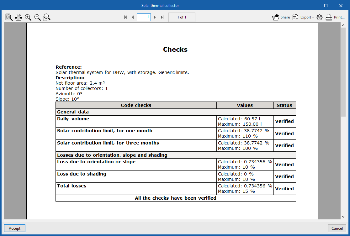
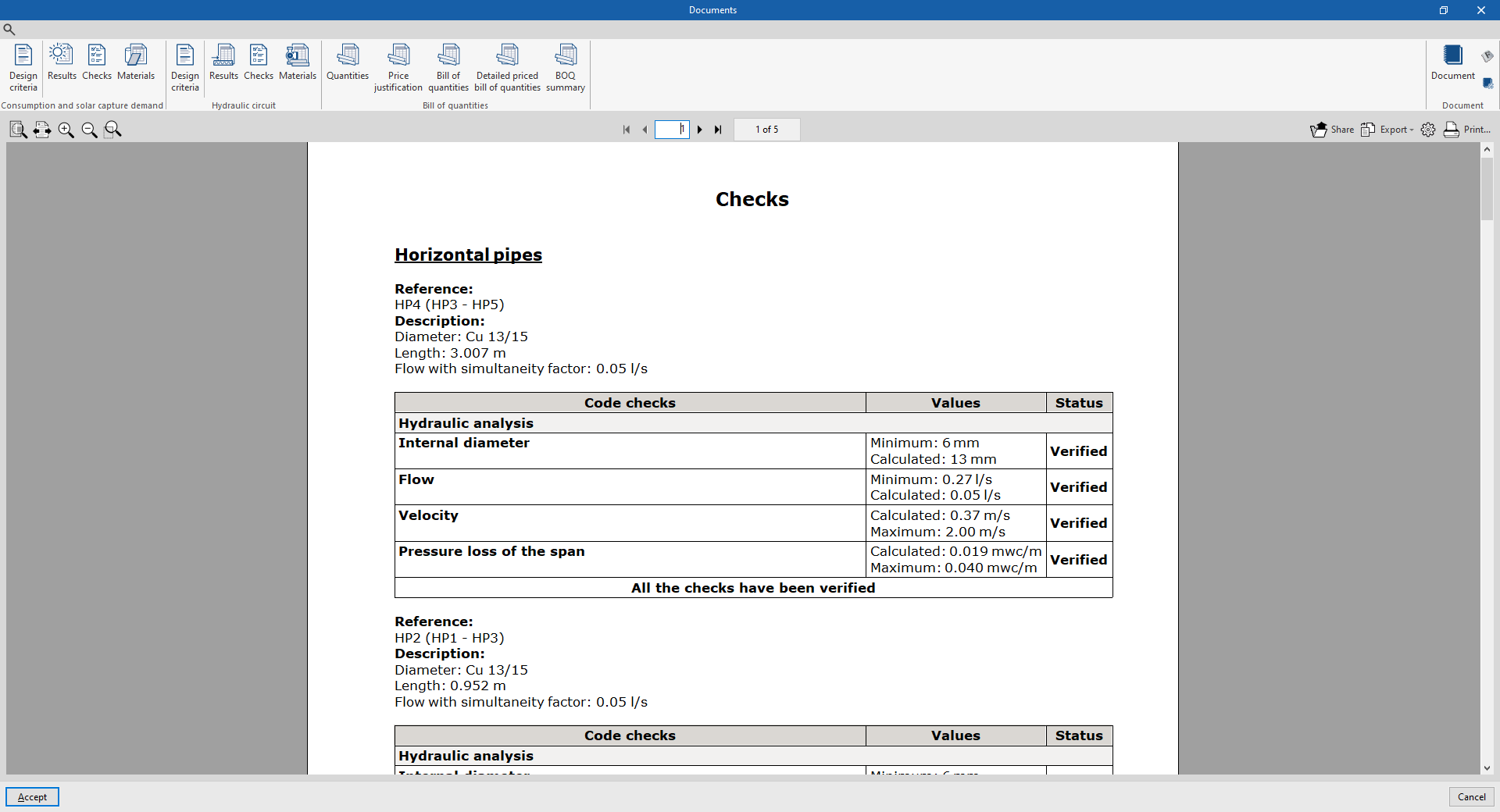
Reports of checks by element
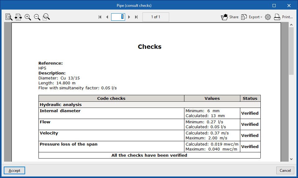
In the editing panel of each element, users can consult the report of specific checks through the corresponding option.
This report includes information with the reference and description of the element, together with a table showing a description of each "Check" carried out, the limit and calculated "Values", and the "Status" of compliance.
This tool is equivalent to the "Consult the checks carried out" option, accessible from the "Calculation" group in the top toolbar.
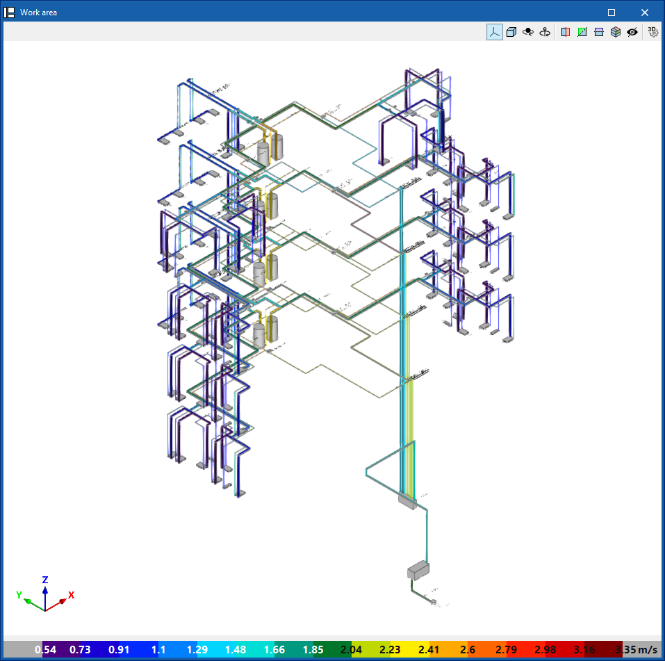
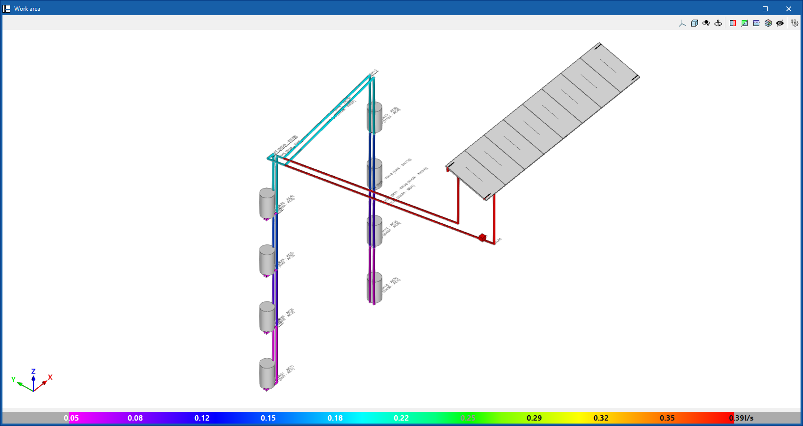
Graphical analysis of results
By means of the "Graphical analysis of results" option in the "Analysis" group in the top toolbar, the calculated values of different magnitudes are displayed by colouring the elements of the solar thermal energy system.
By default, the program shows the minimum and maximum values of each factor obtained in the analysis for the entire system. However, the colour scale can be adjusted according to the specific ranges of minimum and maximum values defined in the corresponding dialogue box.
Reports
The program can print the following reports directly from the printer or generate HTML, PDF, TXT, RTF or DOCX files.
The reports are obtained via the "Reports" option in the top left-hand area of the interface.
Consumption and solar capture demand
The reports on consumption and solar capture demand include the following:
- Design criteria
Displays a report with the expressions and design criteria for the solar collection and storage elements of the system. The following sections are included:- Conditions of use
- Solar energy production calculation
- Solar thermal collectors
- Accumulator tanks
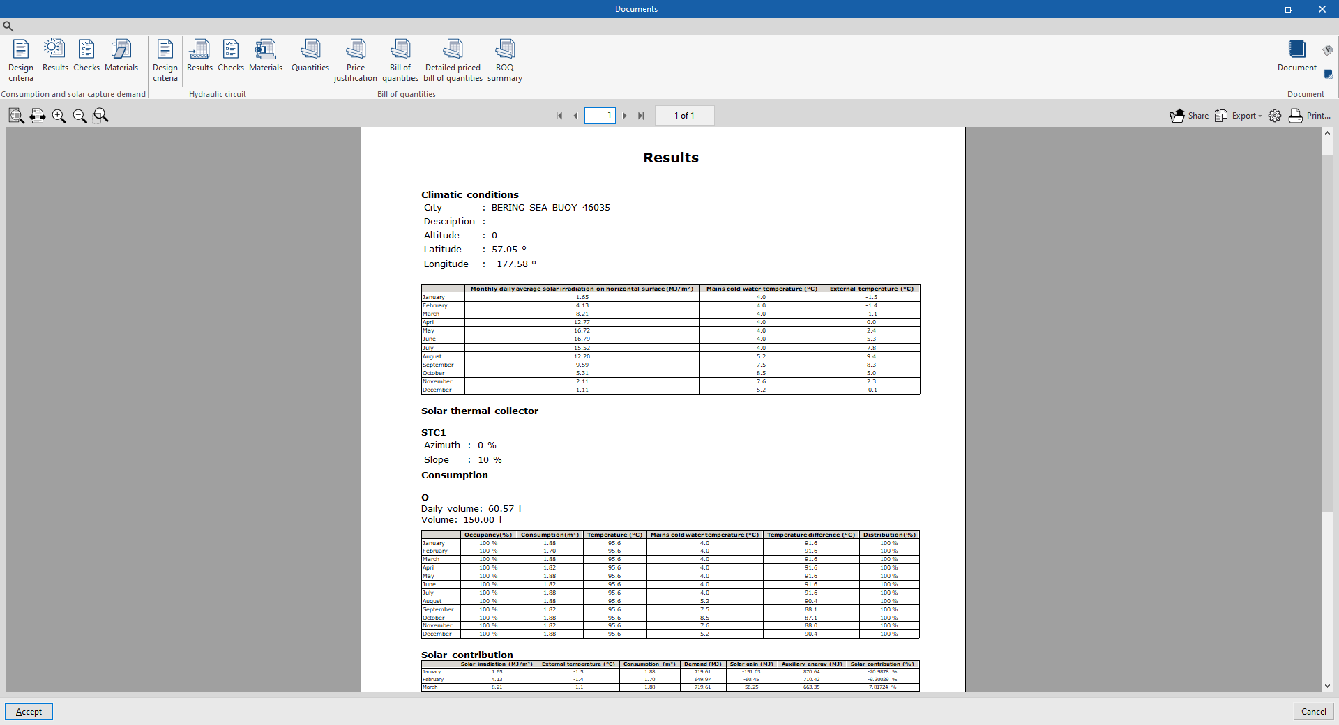
- Results
Displays a report with the analysis results of the solar collectors in the system.
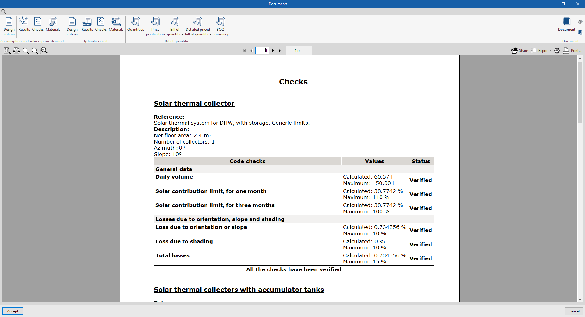
- Code checks
Displays the report of detailed checks of each of the solar thermal collectors and accumulator tanks in the system.
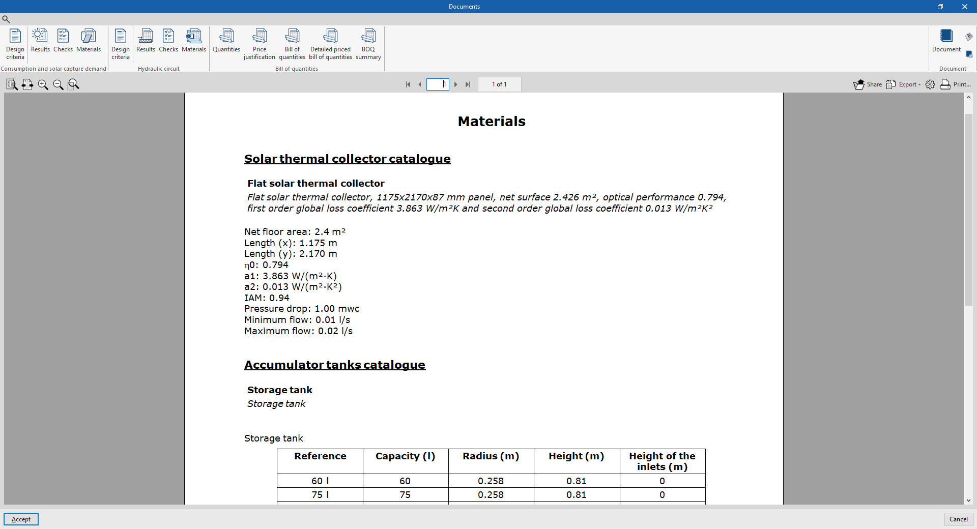
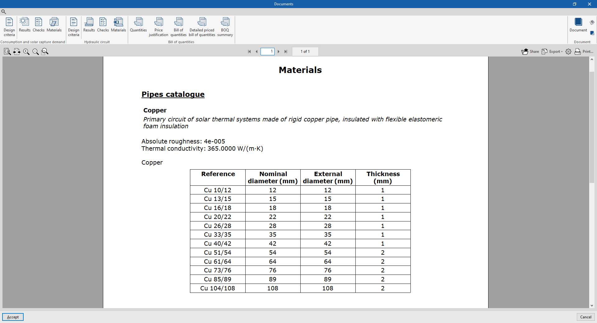
- Materials
Displays a report including the materials used in solar thermal collectors and accumulator tanks.
Hydraulic circuit
The hydraulic circuit reports include the following:
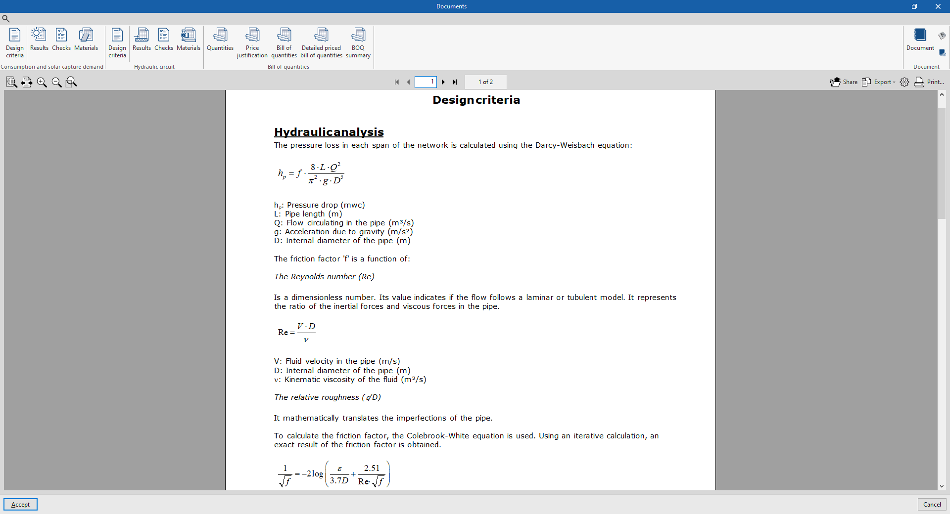
- Design criteria
Displays a report with the expressions and design criteria of the elements in the hydraulic circuit of the system. The following sections are included:- Hydraulic analysis
- Pipes: reference, description, catalogue and entered data for the design and checking
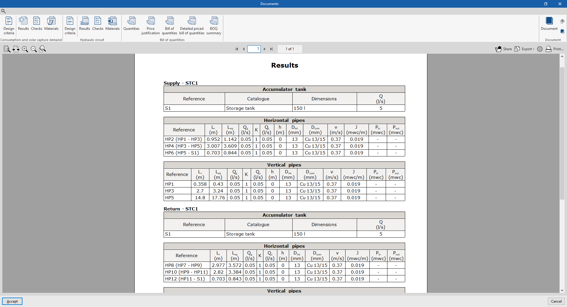
- Results
Displays a report with the analysis results of the hydraulic circuit elements in the system (accumulator tanks, horizontal pipes, vertical pipes).
- Code checks
Displays the detailed check report for each of the pipes in the system.
- Materials
Displays a report including the materials used in the pipes of the system.
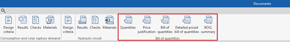
Bill of quantities
This section is used to print the following reports with the information entered in the "Bill of quantities" tab:
- Quantities
- Price justification
- Bill of quantities
- Detailed priced bill of quantities
- BOQ summary
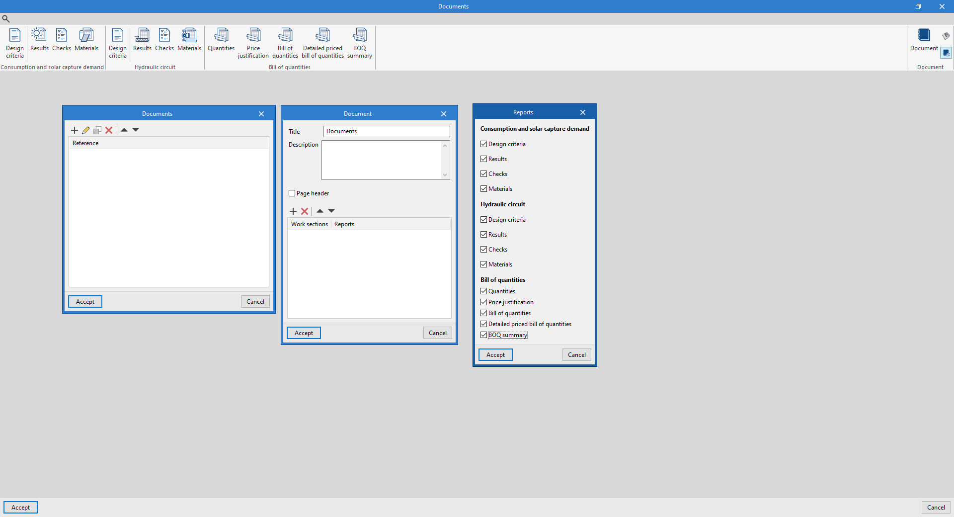
Document configuration
To create documents that incorporate the information of several selected reports together, the options in the right-hand section on document configuration are used. The following data can be configured for each document:
- Title
- Description
- Page header (optional)
- Project; Location; Developer; Author; Date
- Reports to be included
The "Document" option is used to print the document created.
The "Document styles" can also be modified using the corresponding option.
Drawings in DWG, DXF or PDF format
The program can be used to print the drawings of the job on any graphic peripheral configured on the computer or to create DWG, DXF or PDF files.
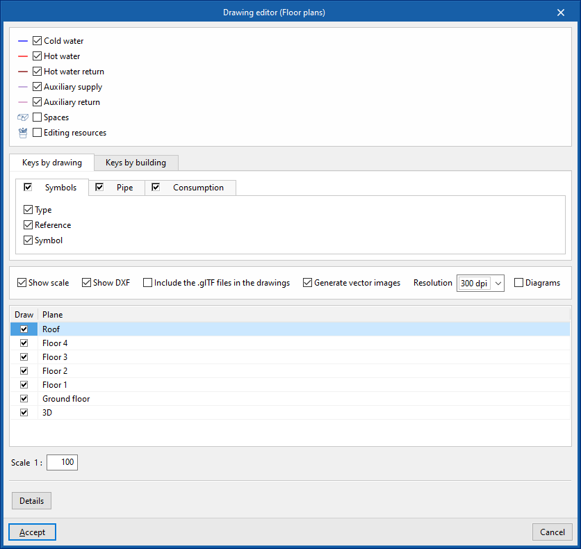
Editing the drawing allows the following options to be configured:
- Selecting categories of elements to be included in the drawing (Supply, Return, Spaces, Roofs, Nearby buildings and other obstacles, Editing resources)
- Keys by drawing / Keys by building
- Symbols (optional) (Type, Reference, Symbol)
- Pipe catalogue (optional) (Reference, Description)
- Accumulator tank catalogue (optional) (Reference, Description)
- Options
- Show scale (optional)
- Show DXF (optional)
- Include the .glTF files in the drawings (optional)
- Generate vector images (optional)
- Resolution (96 ppp / 150 ppp / 300 ppp / 600 ppp)
- Diagrams (optional)
- Selecting 2D or 3D views to be drawn
- Scale
- Details
The drawings can be obtained via the "Drawings" option at the top left of the program's general interface.
Results of the "Bill of quantities" tab
If the work is completed in the "Bill of quantities" tab, the program can obtain the following documents:
- Exporting the bill of quantities in FIEBDC-3 format (BC3)
- Bill of quantities reports (in HTML, PDF, TXT, RTF or DOCX format)
GLTF file compatible with BIMserver.center
When the project is exported to the BIMserver.center platform, an IFC file and a 3D model in GLTF format are automatically exported for the integration of the installation model in the Open BIM project, allowing it to be visualised:
- on the online platform
- in the BIMserver.center app for iOS and Android
- in virtual reality and augmented reality
- in other CYPE programs
Integration into the BIMserver.center platform
Many of CYPE's programs are connected to the BIMserver.center platform and allow collaborative work to be carried out via the exchange of files in formats based on open standards.
Please note that, to work on BIMserver.center, users can register on the platform free of charge and create a profile.
When accessing a program connected to the platform, the program connects to a project in BIMserver.center. This way, the files of the projects that have been developed collaboratively in BIMserver.center are kept up to date.

| More information: |
|---|
| For further details related to using CYPE software via the BIMserver.center platform, please click on this link. |
Options available in CYPEPLUMBING
In the "BIMserver.center" group of the main toolbar of the "Installation" tab, either within the "Water Systems" tab or within the "Sanitary Systems" tab, there are features requires for using CYPEPLUMBING together with other BIMserver.center tools.


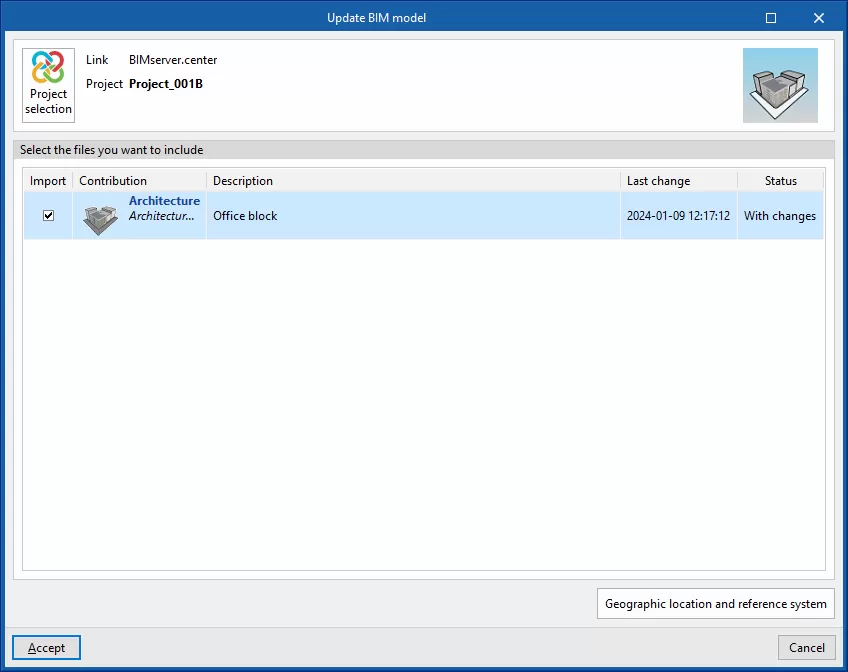
Update
Updates information contained in models previously imported into the project or imports new models if desired.
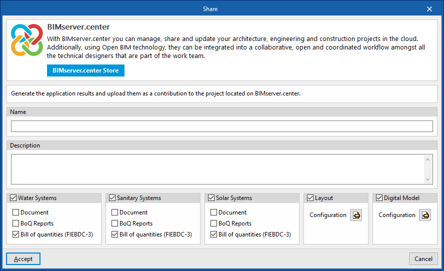
Share
Exports the information of the model developed with CYPEPLUMBING to BIMserver.center to share it with other users, including its 3D representation, the analysis reports, the bill of quantities and the system drawings.
During the export process, users can define the information related to the identification of the files to be exported and select the information to be exported from each of the tabs in the program,"Water Systems", "Sanitary Systems", "Layout" and "Digital Model":
- Name
- Description
- Water Systems / Sanitary Systems / Solar Systems (optional)
You can select the installations and documents to be exported.- Document (optional)
- Bill of quantities reports (optional)
- Bill of quantities (FIEBDC-3) (optional)
- Layout (optional)
- Configuration (optional)
You can select the sheets to be exported from those available and configure the properties of their export.
- Configuration (optional)
- Digital Model
- Configuration (optional)
You can select the detailed models to be exported from those available.
- Configuration (optional)
Importing and sharing files
On the far right-hand side of the main toolbar of the "Installation" tab, either within the “Water Systems” tab or within the "Sanitary Systems" tab, are the tools for importing and sharing files with water supply or water evacuation system information:


These features make it possible for several users to work on different files simultaneously. When the data entry is finished, the information in the files can be dumped and collected in a single file using these options.
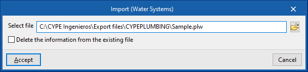
Import
Imports a PLW file with the information of the water supply system (in the "Water Systems" tab) or a PL file with the information of the water evacuation system (in the ‘Sanitary Systems’ tab).
When using this option, the "Import (Water Systems)" or “Import (Sanitary Systems)” window opens, with the following options:
- Select file
Selects a file from the extensions mentioned above and specifies its path. - Delete the information from the existing file (optional)
Activates or deactivates the elimination of the information of the file on which the import is carried out, including the geometry of the existing elements in the system and the options defined in the configuration of the job.
After accepting, the program loads the geometry of the elements in the system saved in the imported file at the same coordinates as in the original file.
Share
Generates a PLW file with the information of the water supply system (in the "Water Systems" tab) or a PL file with the information of the water evacuation system (in the "Sanitary Systems" tab) and saves it in the specified path.
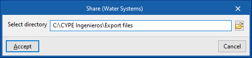
When using this option, the "Share (Water Systems)" or "Share (Sanitary Systems)" window opens, with the following option:
- Select directory
Selects the directory where the file will be saved.
After clicking "Accept", the program generates a file in the specified directory with the same name as the CYPEPLUMBING job and with one of the previously mentioned extensions.
Layer configuration
Within the "Installation" tab of the "Water Systems", "Sanitary Systems" or "Solar Systems" sections, the options that control the display and selection of elements belonging to the model’s various layers are located in the "Layer configuration" panel, which is positioned by default on the left-hand side of the interface.

In addition, the options on the top toolbar of this panel allow you to update the settings for the layers displayed and their colours, control the display of spaces, slats and openings, labels and editing tools, locked elements or those with filters applied, view the graphical analysis of results, activate the display of installations entered in the other tabs of the program, or access the 3D view.
These features are described below.
| Updates the colours in the layer settings based on the information entered for the different element types in the "General options" section, within the "Project" group. | |
| Updates the layer settings based on new elements added to the model (for example, by displaying or adding the layer corresponding to the category of the newly added element). | |
| Toggle the display of all areas of the BIM model that have been read and imported into the program in all views. | |
| Enables or disables the display in all views of horizontal or vertical pipe runs defined using the options in the "Generation" menu. | |
| Enables or disables the display of doors or openings from the BIM model that have been imported into the program in all views. | |
| Toggle the display of installation element labels in all views. | |
| Enables or disables the display in all views of annotations entered using the tools in the "Annotations" menu of the "Edit" panel. | |
| Highlight the locked items using the "Lock" option in the "Edit" section of the top toolbar. | |
| Highlight the items assigned to filters using the options in the "Bill of quantities" menu, within the "Edit" section of the top toolbar. | |
| This allows you to view a graphical analysis of the results of the last analysis. | |
| Enables or disables the display of water supply system components entered in the "Water Systems" tab (in the "Sanitary Systems" and "Solar Systems" tabs). | |
| Enables or disables the display of solar thermal system components entered in the "Sanitary Systems" tab (in the "Water Systems" and "Sanitary Systems" tabs). | |
| Toggle the display of the water drainage system components entered in the "Solar Systems" tab (in the "Water Systems" and "Solar Systems" tabs). | |
| This allows you to open a 3D viewer in a separate window displaying elements imported from the BIM model alongside the model’s own elements. |
Tools in the "3D view" group
In the "3D view" group of the main toolbar of the "Installation" tab, either in the "Water Systems" tab or in the "Sanitary Systems" tab, the following tools can be found:


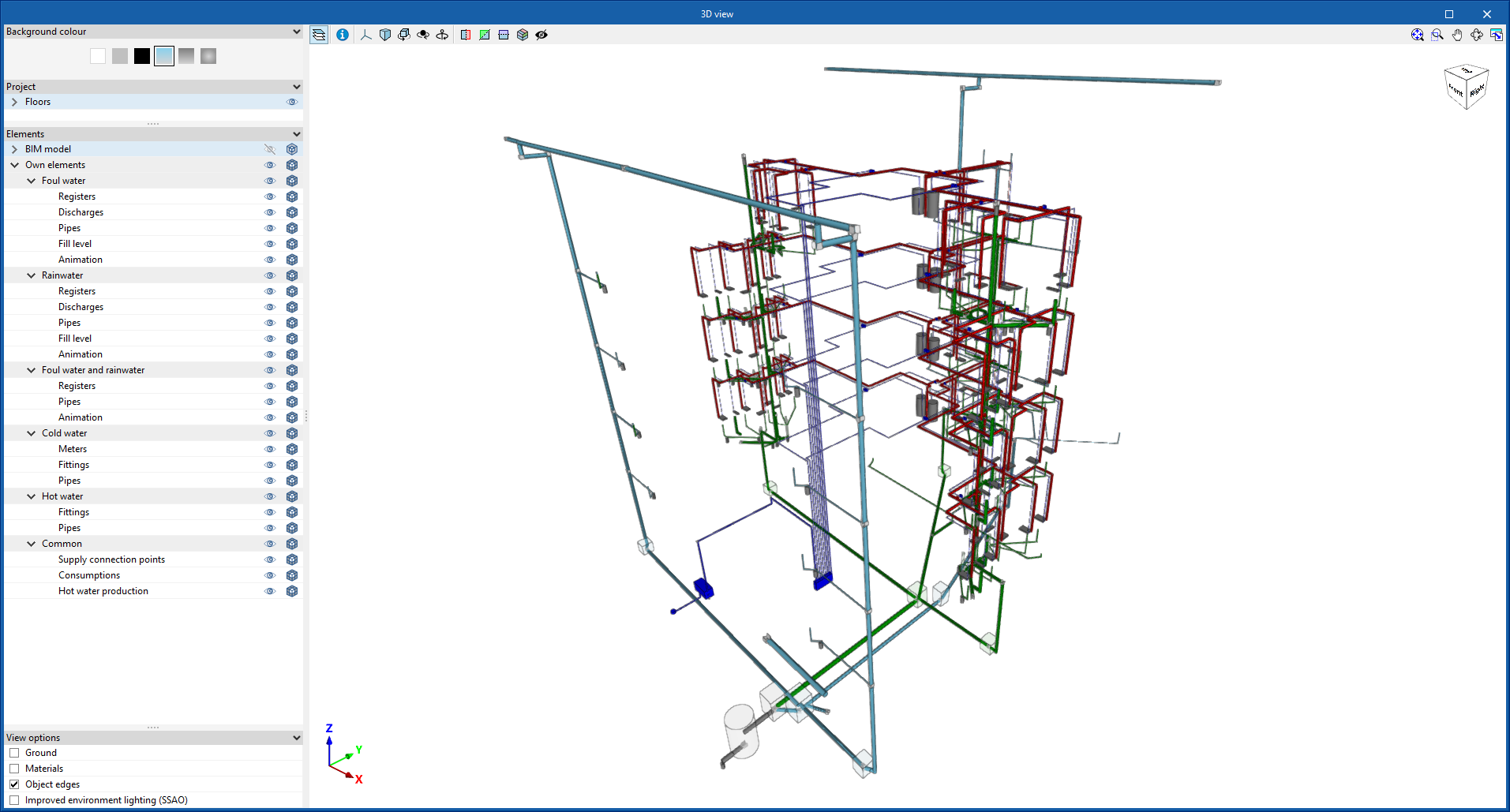
3D view
This opens a 3D viewer where the elements read from the BIM model and the elements entered in the different tabs of the program are displayed together.
Visibility
This isolates the display of the elements selected in the work area in all views of the model, hiding the rest.
Redraw
This displays all elements in the model in all views, undoing the operation performed by the "Visibility" option.
Generating and laying out solar thermal energy system diagrams
The "Diagram" tab, available at the top of the "Solar Systems" tab, allows users to automatically generate the diagrams of the solar thermal system from the model information developed in the "Installation" tab, or to create them manually using the available drawing tools:
- To create the diagrams from scratch, the necessary format sheets are first created using the options on the left-hand side. Then, the schematic elements are entered in the work area on the right-hand side using the options in the top toolbar.
- To generate the layouts automatically, the "New" option at the top is used. It is then possible to modify the generated diagrams in the work area using the options in the top toolbar.
Composite drawings can be selected in this tab to be printed together with the rest of the drawings of the job using the corresponding options.
Diagram management
The diagrams of the solar thermal energy system are made up on sheets of different formats. The tools for creating and managing diagrams are located on the left-hand side of the interface.
The following features can be configured when creating or editing a diagram:
- Reference
- Description
- Paper format
The available paper formats can be configured in ‘General Options’. - Orientation (Landscape / Portrait)
- Scale factor (%)
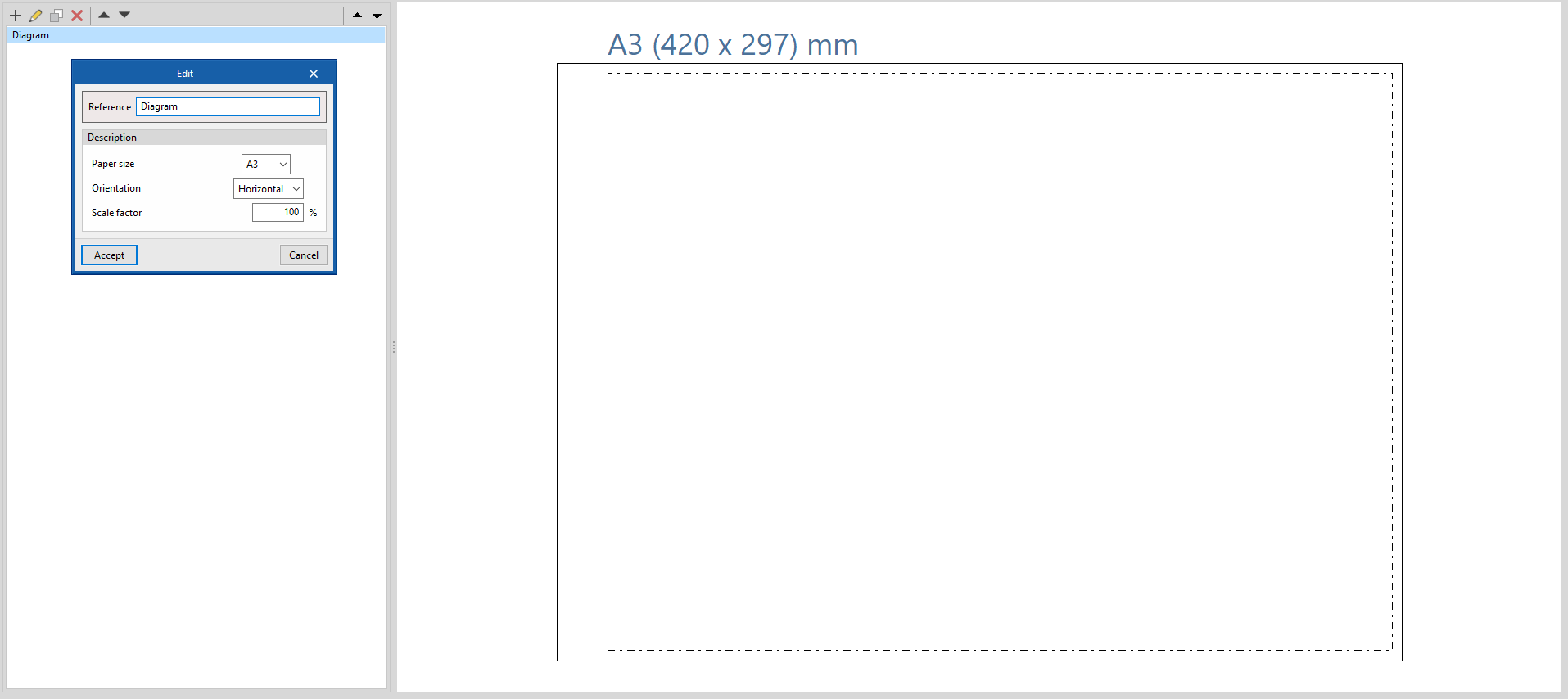
Options in the "Project" group
In the "Project" group of the top toolbar, the program offers the following utilities:
General options
This configures the available paper formats and table types, the units of measurement, and the graphic representation of the elements of the solar thermal energy system diagrams, defining their colour and symbols.
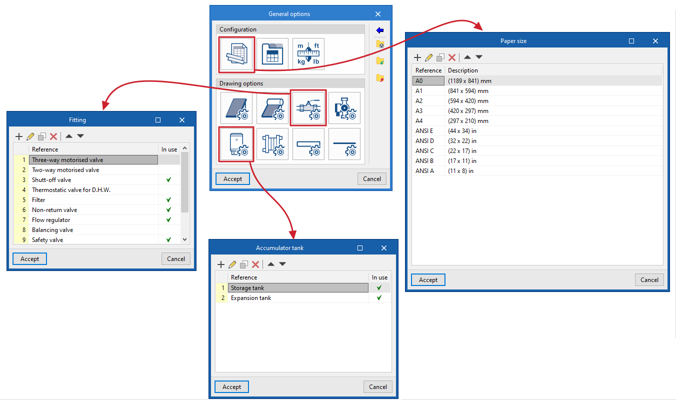
Symbols
Used to create and edit the symbols of the system elements by means of a drawing editor. The symbols contained in DXF, DWG or DWF files saved on disk can be imported. These symbols can be selected in the configuration defined for each element under "General options
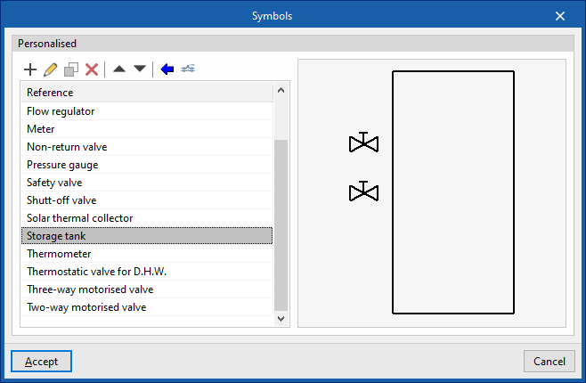
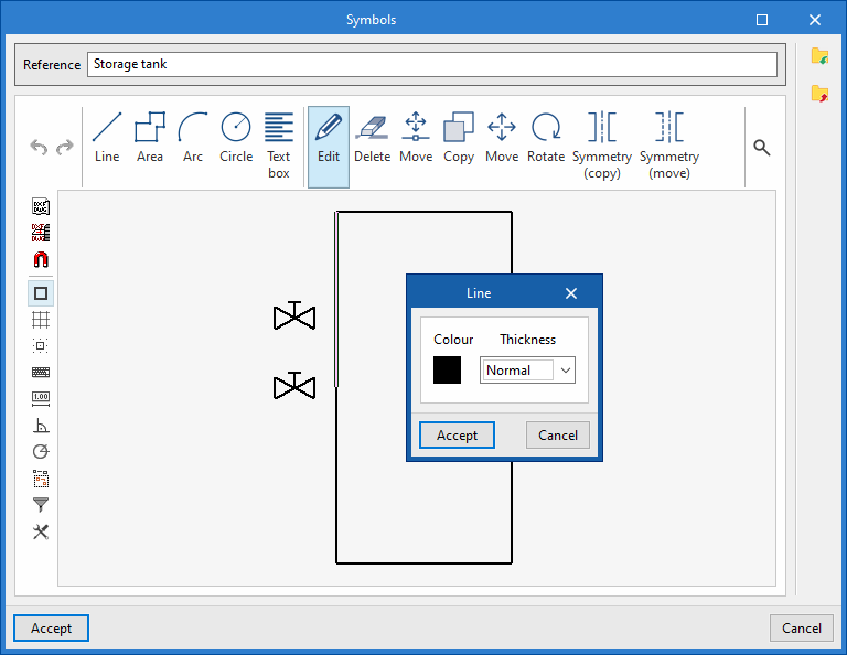
Options in the "Diagram" group
In the "Diagram" group of the top toolbar, the program offers the following options:
Update results
Updates the information available for generating new diagrams with the results of the analysis.
New
Automatically generates the diagram of the solar thermal system if the model contains the appropriate information.
The diagrams generated can be further modified using the tools available at the top.
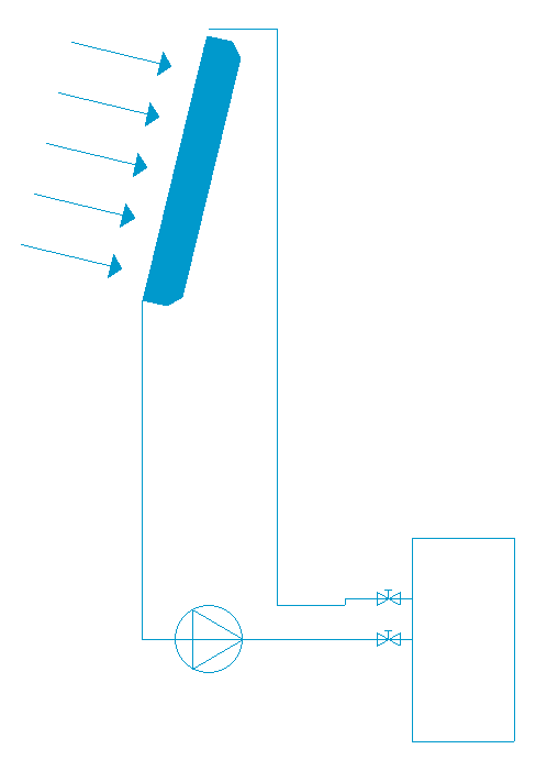
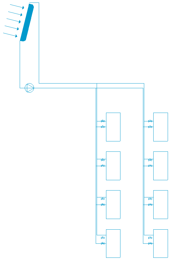
Tools for entering diagram elements
These options allow users to freely enter these elements in the diagram of the solar thermal system:
- Solar thermal collector
- Solar thermal collector with accumulator tank
- Fitting
- Pump
- Storage tank
- Heat exchanger
- Pipe
In each of them, the following parameters are defined:
- Reference
Reference of the particular element. - Drawing options
Selects the symbol previously defined in the "Drawing options" of the "General options".
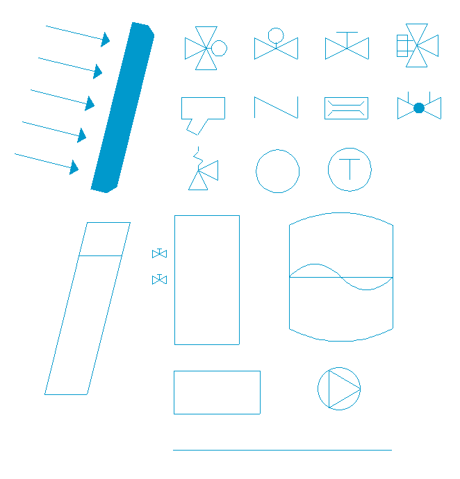
Reference line
Enters a reference line. These lines can be used to indicate the layout of the diagram elements on the different floors of the building.
User tables
Inserts legends or tables with complementary information in the diagrams.
When a table is created, it can be "Generic", for which the number of rows and tables is specified and the content of its cells is filled in a free editor, or "Key" type, in which case it can be "Automatically generated" according to the elements arranged in the diagram.
Table types can also be managed via the corresponding option in the "General options".
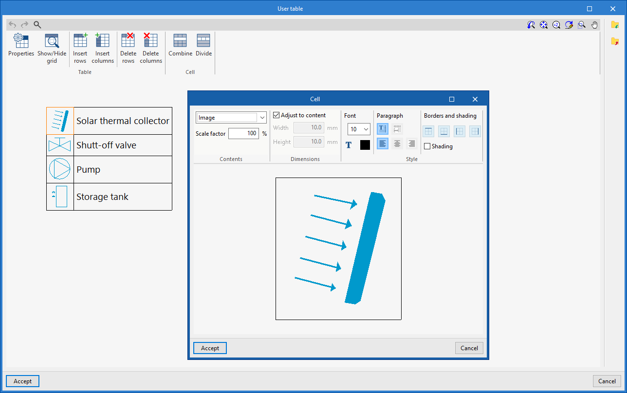
Editing tools
The options in this menu are used to perform the following operations to edit the elements of the system diagram:
| Edit | Edits the parametric properties of the selected element in the model. | |
| Copy | Creates a copy of one or more elements. | |
| Move element | Moves an element or a node of an element. | |
| Move a group of elements | Moves a group of elements. | |
| Delete | Deletes a previously entered element. | |
| Rotate | Rotates an element. | |
| Measure lengths on plan | Measures lengths and angles between points defined in the model. If a closed outline is selected, it also indicates the area. |
Drawing tools
The options in this menu are used to enter the following drawing resources:
| Elevation | Enters an elevation between two selected points, indicating the line colour, line thickness, and text size. | |
| Line | Inserts a line between two selected points, indicating its colour and thickness. | |
| Text | Enters a text and a reference line, indicating its colour, the line thickness and the text size. | |
| Text box | Enter a left-aligned, right-aligned or centred text box, indicating the colour and size of the text, the properties of the frame and the background fill. | |
| Arc | Enter an arc and, optionally, its radius, indicating the line colour, line thickness and text size. | |
| Circle | Enter a circle and, optionally, its radius or diameter, indicating the line colour, line thickness, and text size. | |
| Rectangle | Enter a rectangle and, optionally, its area, indicating the line colour, line thickness and text size. | |
| Area | Enter a dotted polygon and, optionally, its area, indicating the line colour, line thickness, and text size. | |
| Polyline | Inserts a polyline by points, indicating its colour and thickness. | |
| Edit | Edit the properties of the selected drawing resource. | |
| Delete | Deletes the selected drawing resources. | |
| Move | Moves the selected drawing resource or parts of it. | |
| Assign | Assigns the properties of a drawing resource to others. When selecting a drawing resource, resources with the same properties are highlighted in orange. |
Table of contents
Complete your tour of CYPEPLUMBING by exploring the other sections available: