Editing tools
In the "Edit" section of the main toolbar on the "Installation" tab, within the "Water Systems", "Sanitary Systems" or "Solar Systems" tabs, you will find the following tools:


Edit
The options in this menu allow the following editing operations to be carried out on the elements of the system entered in the model:
| Edit | Edits the parametric properties of the selected element in the model. | |
| Delete | Deletes a previously entered element. | |
| Move element | Moves an element or a node of an element. | |
| Move a group of elements | Moves a group of elements. | |
| Rotate element | Rotates an element about the "x", "y" or "z" axis. | |
| Rotate a group of elements | Rotates a group of elements. | |
| Copy | Creates a copy of one or more elements. | |
| Assign | Assigns the parametric properties of the selected element to other elements. | |
| Symmetry (copy) | Copies a selection of elements with symmetry with respect to a vertical plane defined by two points. | |
| Symmetry (move) | Moves a selection of elements with symmetry about a vertical plane defined by two points. | |
| Copy onto another floor plan | Creates a copy of the selected elements in the desired floor plans. This feature is only available on floor plans. | |
| Add points | Adds intermediate points along the pipes. The pipe remains a single, undivided element. | |
| Delete points | Deletes intermediate points on pipes. The pipe remains as a single, undivided element. | |
| Join | Joins two pipes into a single pipe, creating a connecting section if necessary. The resulting pipe takes on the properties of the first pipe selected when this option is used. | |
| Split | Splits a pipe in two at the selected point. | |
| Measure lengths on plan | Measures lengths and angles between points defined in the model. If a closed outline is selected, it also indicates the area. | |
| Projection | Switches to the plan projection (XY plane) in the work area. |
Label
The options in this menu allow you to perform the following operations on the tags of the elements:
| Move tag in 2D mode | Moves the selected tag on the element's floor plan. | |
| Move tag in 3D mode | Moves the selected tag in the 3D space. | |
| Move tag to the initial point | Returns the tag of the selected element to the initial point. | |
| Show/hide tag | Shows or hides the line linking the tag to the selected element it refers to. | |
| Place or remove the reference line of the tag | Shows or hides the line linking the tag to the selected element it refers to. | |
Rotate tag | Rotates the tag over its position. | |
| Tag | Edits the composition of the labels of different categories of elements and the size of the text. |
Notes
The options in this menu allow you to insert the following drawing elements into a floor plan:
| Note: |
|---|
| You can enable or disable the display of these elements using the "Editing resources" option in the "Layer settings" panel, which is located by default on the left-hand side of the main interface. |
Elevation | Enters an elevation between two selected points, indicating the line colour, line thickness, and text size. | |
| Line | Inserts a line between two selected points, indicating its colour and thickness. | |
| Text | Enter a text and a reference line, indicating its colour, the line thickness and the text size. | |
| Text box | Enters a left-aligned, right-aligned or centred text box, indicating the colour and size of the text, the properties of the frame and the background fill. | |
| Arc | Enters an arc and, optionally, its radius, indicating the line colour, line thickness and text size. | |
| Circle | Enters a circle and its radius or diameter, optionally, indicating the line colour, line thickness, and text size. | |
| Rectangle | Enters a rectangle and, optionally, its area, indicating the line colour, line thickness and text size. | |
| Area | Enters a dotted polygon and, optionally, its area, indicating the line colour, line thickness, and text size. | |
| Polyline | Inserts a polyline by points, indicating its colour and thickness. | |
| Edit | Edits the properties of the selected drawing resource. | |
| Move | Moves the selected drawing resource or parts of it. | |
| Copy | Creates a copy of one or more drawing resources. | |
| Assign | Assigns the properties of one drawing resource to others. When you select a drawing resource, any resources with the same properties are highlighted in orange. | |
| Move a group of elements | Moves a group of elements. | |
| Rotate a group of elements | Rotates a group of elements. | |
| Symmetry (move) | Moves a selection of elements with symmetry about a vertical plane defined by two points. | |
| Symmetry (copy) | Copies a selection of elements with symmetry with respect to a vertical plane defined by two points. | |
| Delete | Deletes a previously entered element. |
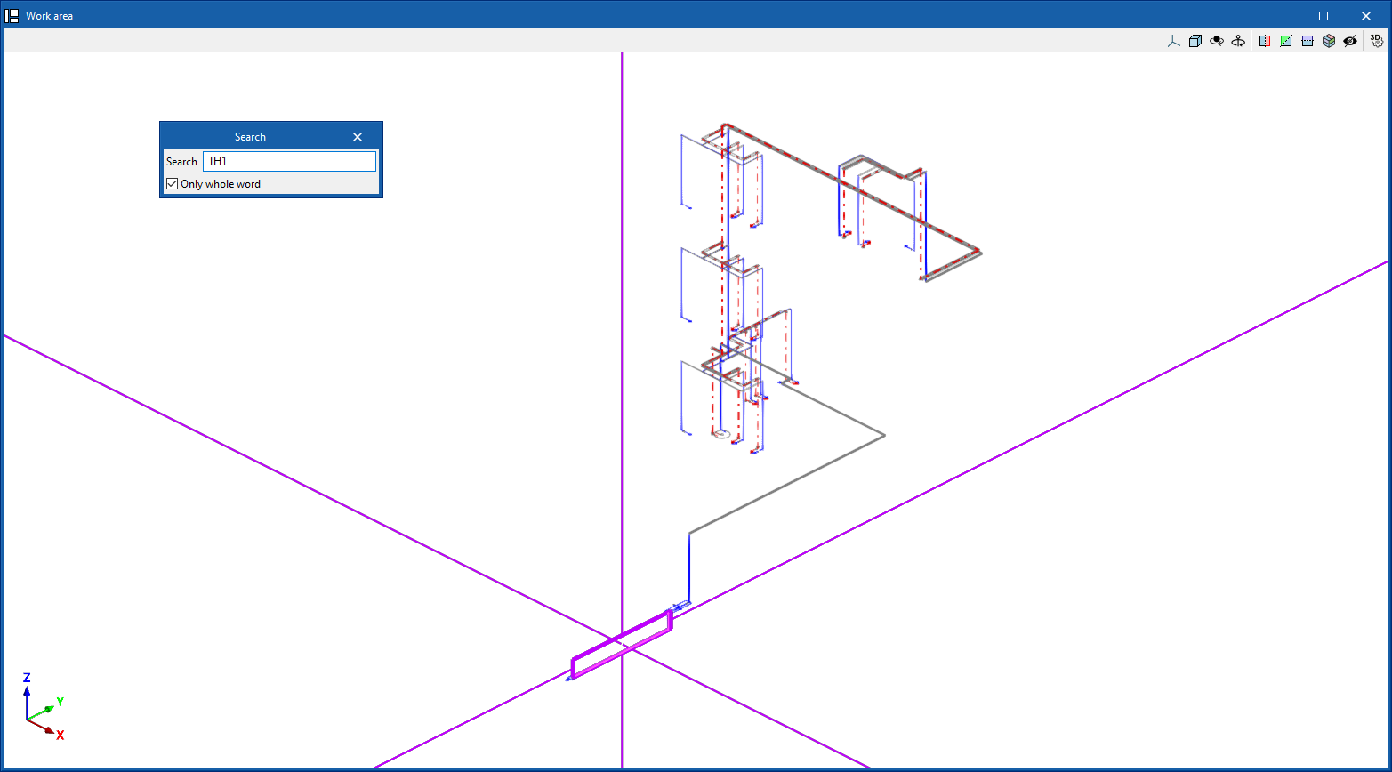
Search
Searches for an element by entering a text with its full reference or part of its reference.
- Only whole word (optional)
If this box is checked, only the elements that match the entered text in full will be searched for.
When doing this, the program locates the element in the model by means of magenta lines in the main directions of the space and an enveloping volume of the same colour.
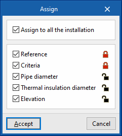
Lock
This option allows you to lock or unlock various definition parameters for model elements so that the program keeps them unchanged when updating results.
This can be done for the selected items in the workspace or, if the following box is ticked, for all items in the installation:
- Apply to the entire installation (optional)
The settings available for locking or unlocking are as follows:
- Reference (optional)
- Criteria (optional)
- Pipe diameter (optional)
- Thermal insulation diameter (optional) (under the "Water Systems" and "Solar Systems" tabs)
- Elevation (optional)
The icon on the right allows you to choose whether to lock or unlock each of the selected settings.
| Nota: |
|---|
| These settings can also be locked or unlocked in the edit panel for each element. |
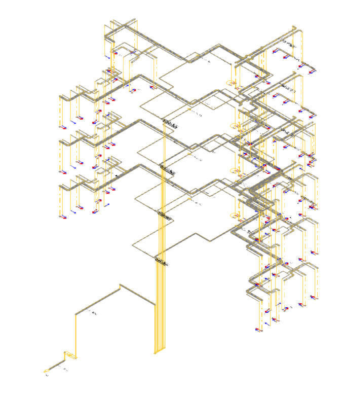
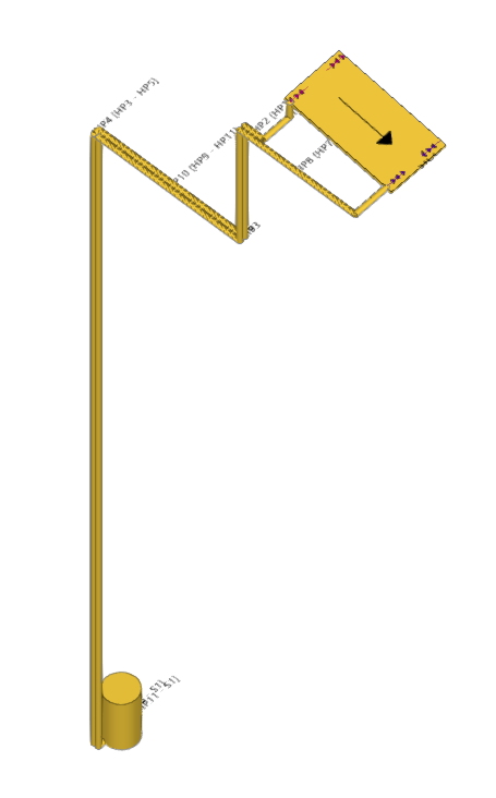
Viewing locked items
The "View locked items" option in the "Layer configuration" panel on the left-hand side highlights model elements in the workspace in yellow if any of the parameters mentioned in the previous option are locked, making them easier to locate.
Bill of quantities
The "Bill of quantities" option opens a menu containing the following tools:
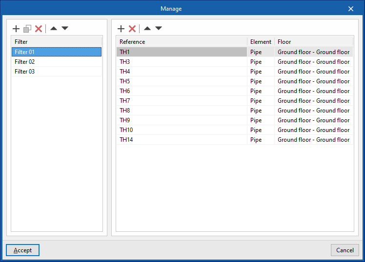
- Filter
Opens a filter manager where you can create filters on the left-hand side and assign them to the desired system components on the right-hand side. - Add
Creates a filter and applies it to the selected items in the workspace. - Delete
Removes the filter assignment from the selected items in the workspace. If the filter assignment is removed from all items, the filter is deleted. - Edit
Edit the filter settings for the selected item in the workspace.
Displaying elements with filters applied
The "Show filters" option in the "Layer settings" panel on the left-hand side displays the model elements, colour-coding them according to the filter to which they are assigned.
| Note: |
|---|
| Filters can also be created and assigned in the edit panel for each element. Filters created and assigned to elements allow for greater control over the bill of quantities generation process. |
Layers
In the "Edit" section, the program offers the following two controls relating to the model’s layers.
The first button allows you to "Update layer settings based on the elements entered in the model". This option is equivalent to the one available in the "Layer settings" panel on the left-hand sidebar.
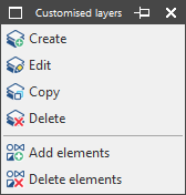
The second button can be used to create and manage "Customised layers". Clicking this button opens a menu with the following options:
- Create
Creates a new custom layer by entering a "Reference". - Edit
Edits the "Reference" of the currently selected custom layer. - Copy
Duplicates the currently selected custom layer. - Delete
Deletes the currently selected custom layer. - Add elements
Selects elements from the model and assigns them to the custom layer selected in the pop-up window’s drop-down menu. To facilitate this operation, you must first select a category of elements in which those elements are visible. - Delete elements
Deletes the assignment of the selected elements from the model to the custom layer selected in the layer list.
You can select, configure, hide and/or control the display of "Customised layers" from the relevant section of the "Layer settings" panel in the left-hand sidebar.
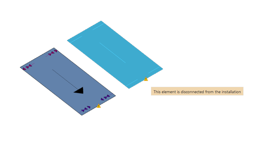
Check
Keeping this option activated highlights the elements in the system where a warning or error has occurred in relation to their insertion or editing by means of an incident system, as in the case of disconnected elements, when they were inserted in the model. The descriptive message of said warning or error is displayed by hovering the cursor over each warning or error.