Inserting collectors in a solar thermal system
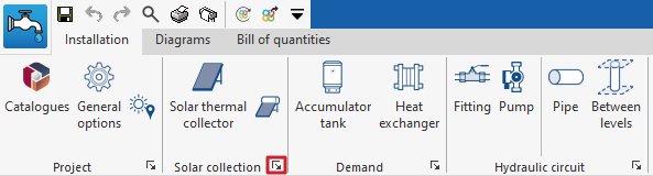
Under the "Installation" tab in the "Solar Systems" section, within the "Solar Collection" group on the main toolbar, you will find the options for adding collectors to the solar thermal energy system:

Solar thermal collector / Solar thermal collector with storage tank
These two options allow for the installation of solar thermal collectors (without integrated storage) or solar thermal collectors with storage tanks (including compact systems or thermosiphon systems), respectively.
When adding or editing a solar thermal collector, you can configure the following parameters. Some of these appear only if the "Simplified entry" option under "Design options" in "General options" is disabled:
- Reference
The reference for the element. This value can be locked or unlocked. If it is unlocked, the program will create or modify the reference when updating results. - Solar thermal collector
This allows you to select the criteria or options for sizing and checking solar thermal collectors. These options can be created and edited under "Design and check options" in "General options", within the "Project" section. - Material reference
This allows you to select the reference for the material or equipment associated with the solar thermal collectors from the relevant catalogues in the "Selection of materials and equipment" section, under "General options", within the "Project" group. - Maximum losses due to orientation, tilt and shading
Displays the maximum losses due to orientation, tilt and shading associated with the solar thermal collector selected above.
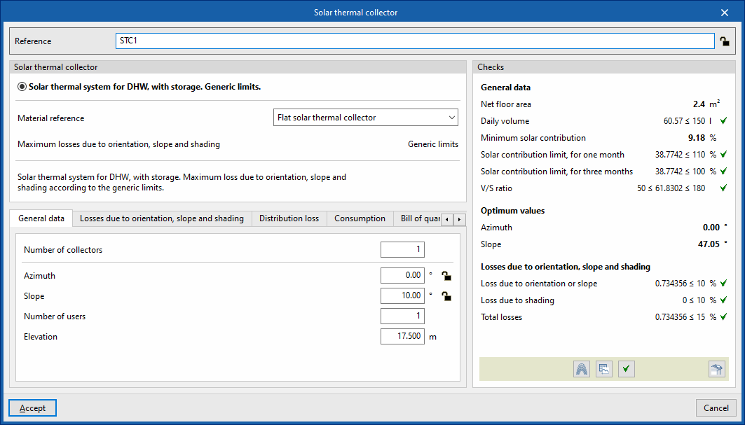
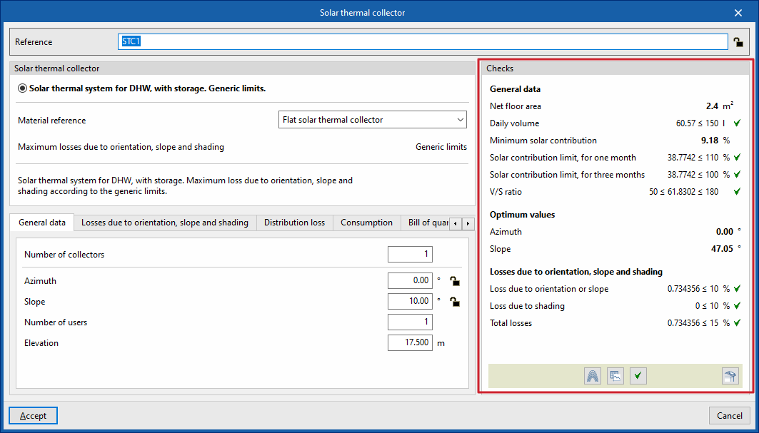
- "General data" tab:
Allows you to define general details of the element entered, such as the number of collectors, their spatial layout, the number of subscribers and their elevation.- Number of collectors
- Azimuth (Lock/Unlock)
The angle of the sensor relative to the south. This value is taken from the element’s definition in the model. - Slope (Lock/Unlock)
- Number of users
- Elevation
Elevation of the sensor insertion point.
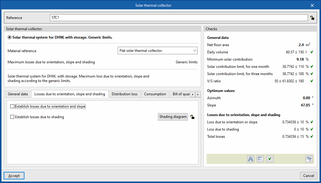
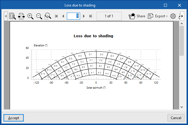
- "Losses due to orientation, slope and shading" tab
- Establish losses due to orientation and slope (optional)
- Establish losses due to shading (optional)
- Shading diagram (Lock/Unlock)
The shading diagram over the sensors is generated automatically during the calculation.
- Shading diagram (Lock/Unlock)
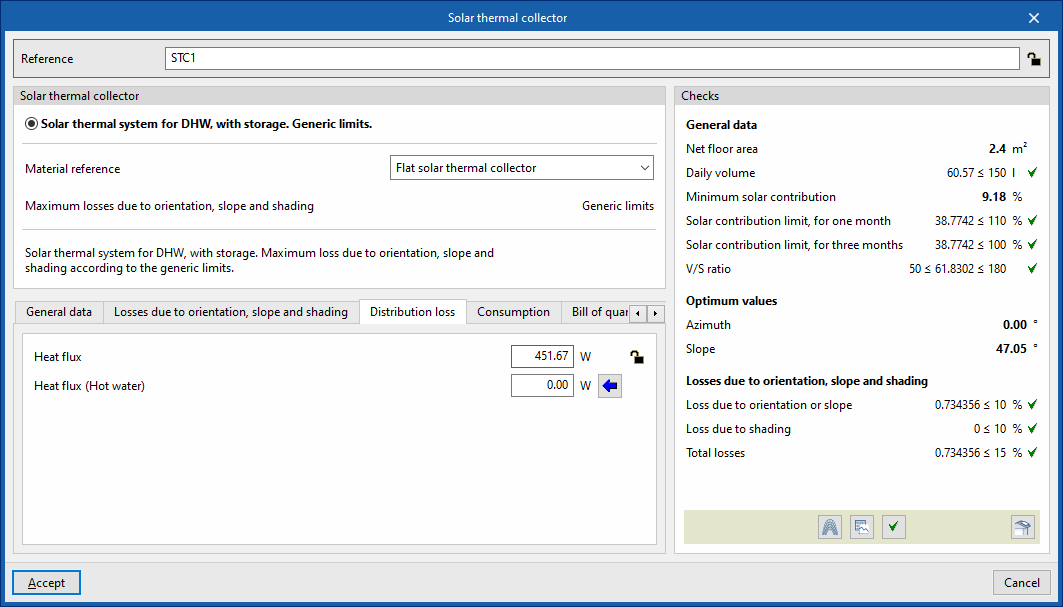
- "Distribution loss" tab:
Allows you to define the distribution losses associated with the collector.- Heat flux (Lock/Unlock)
- Heat flux (DHW)
The wizard on the right allows you to calculate this value using the following data:- Equivalent length
- Temperature
- Inner diameter
- Thickness
- Thermal conductivity
- Insulation (optional)
- Thickness of the thermal insulation
- Thermal conductivity of insulation
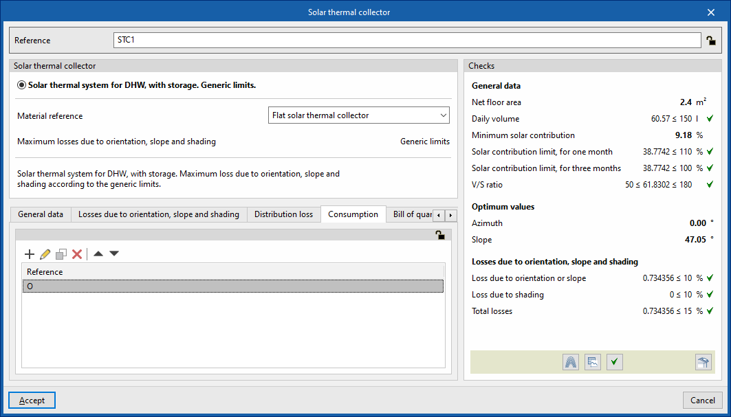
- "Consumption" tab (Lock/Unlock)
Allows you to manage the consumption data associated with the sensor by editing entries in a table. When entering consumption data, you must provide the following information:- Reference
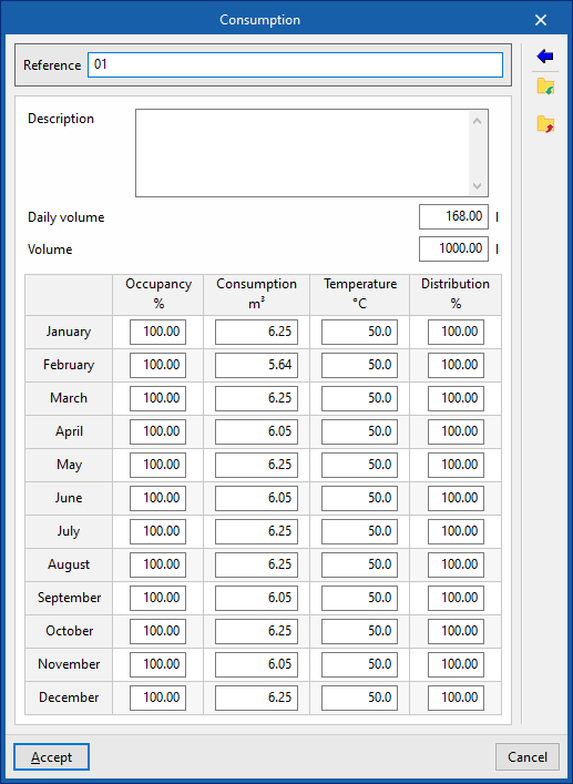
- Description
- Daily volume
- Volume
- Occupancy (%) / Consumption (m³) / Temperature (°C) / Distribution (%)
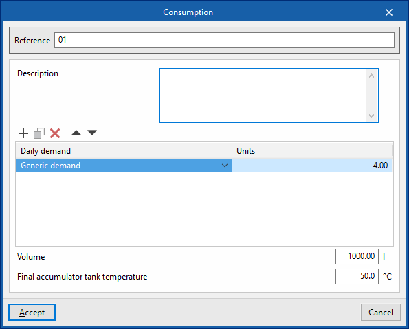
These figures are calculated for each month. - Usage
Using this button, located on the right-hand side of the panel, you can load this data using the following values:- Reference
- Description
- Daily demand, per unit / Units
The values for "Daily demand, per unit" can be configured under "Demand criteria", within "Design options", and, in turn, under "General options". In addition, you must enter the number of "Units" associated with the equipment. - Volume
- Final storage tank temperature
- "Bill of quantities" tab:
Allows you to control the generation of the element's bill of quantities using filters.- Solar thermal collector
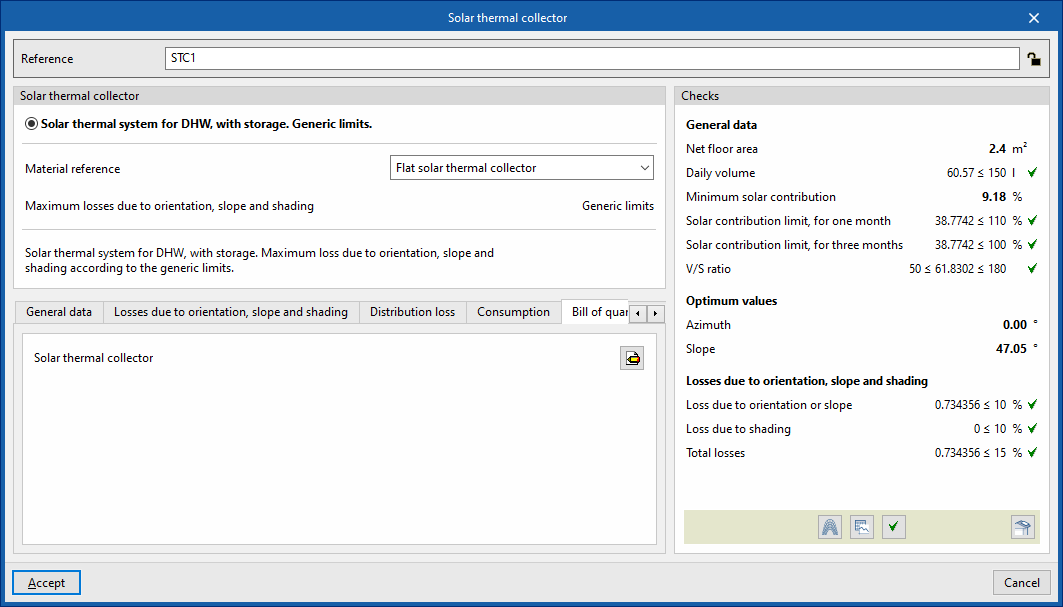
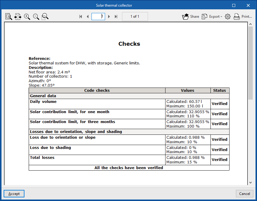
- Checks
Allows you to view and list the checks performed on the element. The tools in the bottom centre allow you to view graphs, tables and design reports. In addition, the tool in the bottom right-hand corner allows you to perform a partial design of the element using the data entered in the panel.- Shadow losses
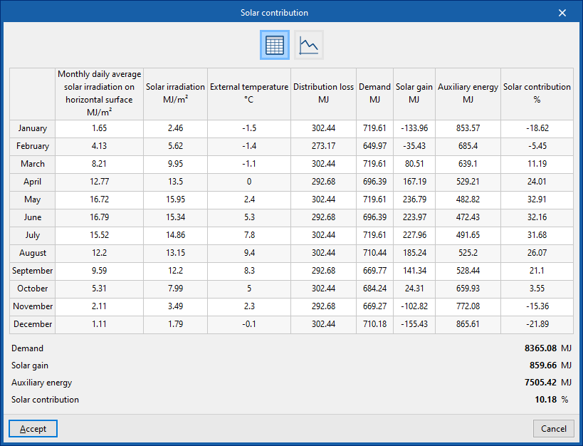
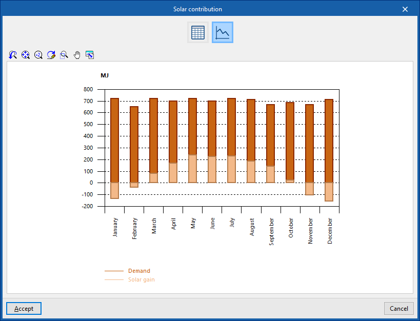
- Solar contribution
- View calculation results (formulae, checks, etc.).
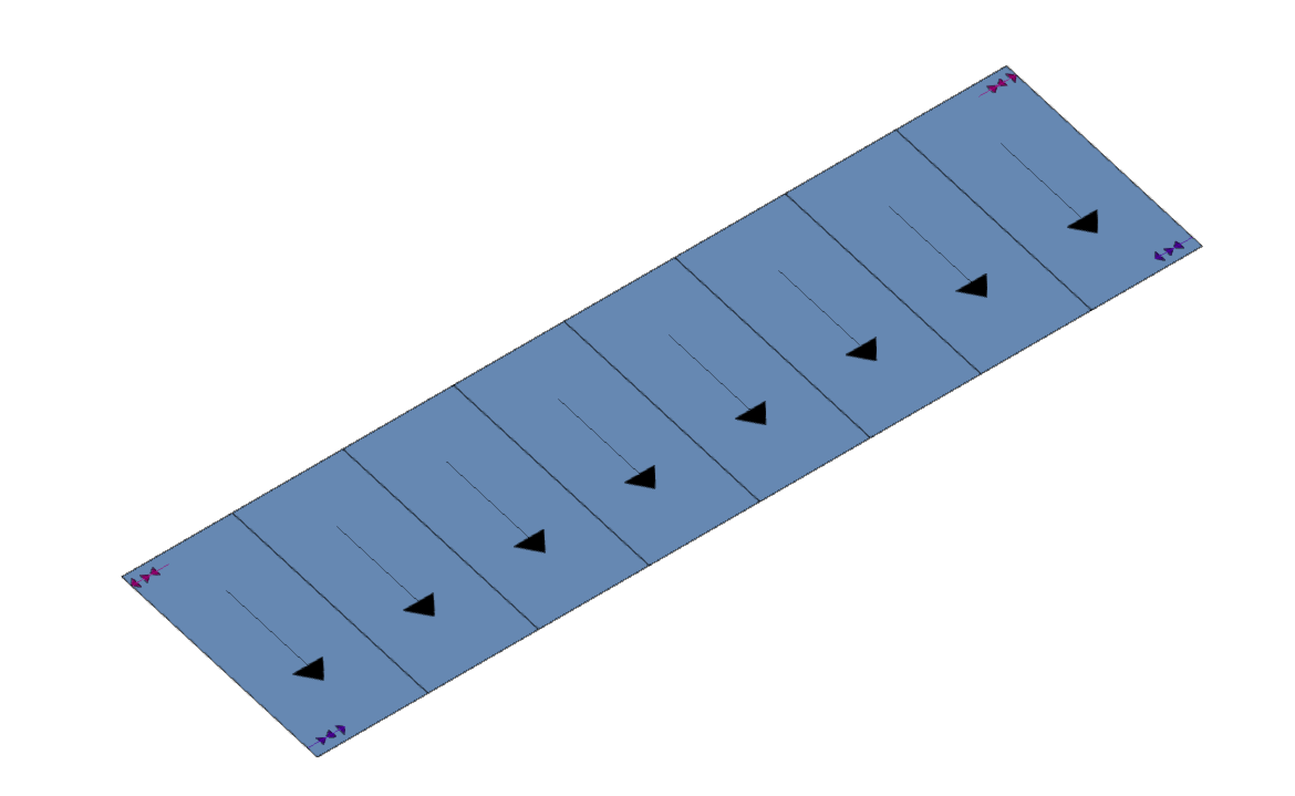
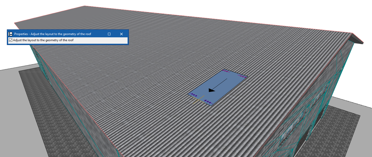
Positioning of the solar thermal collector in the "Work area"
When placing the solar thermal collector in the workspace, the program allows you to tick the box labelled "Adjust layout to roof geometry". If this option is selected, when you click on a sloped plane, the collector will adopt the "Slope" value based on the roof data from the model.
| Note: |
|---|
| The button in the bottom-right corner of the "Solar collection" group allows you to access the configuration options for the elements in this group. These options are the same as those available under "Design and check options" in "General options", within the "Project" group. |