


Joints V. Flat trusses with hollow structural sections
The "Joints V. Flat trusses with hollow structural sections" module for CYPECAD, its Integrated 3D structures and CYPE 3D, carries out an automatic analysis and design of coplanar hollow structural section connections, like those which are usually provided in flat trusses. Even though the first version of the module only includes welded connections with circular sections, more features will be incorporated including bolted connections, rectangular and square hollow sections, channels welded in a box and the necessary combinations for this type of structure.
More information on the types of joints that can be designed and the codes that can be applied can be found at Types of implemented connections for flat trusses with hollow structural sections and Implemented design codes for the design of flat trusses with hollow structural sections.
Types of implemented connections for flat trusses with hollow structural sections
Bearing in mind the geometric shape of the bars at the node, the implemented joints belonging to flat trusses with hollow structural sections are displayed below:
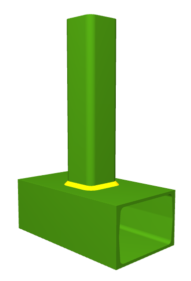

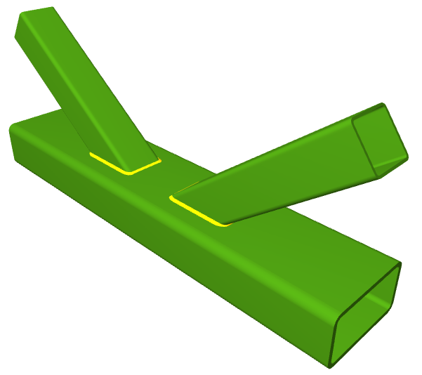


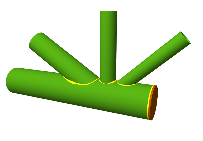
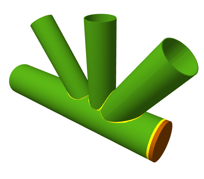
(1) If the chord of the truss consists of rectangular hollow sections (or square or two channels welded in a box), the diagonals and vertical bars can be circular, rectangular or square hollow sections, or double rolled channels. If the chord consists of circular hollow sections, the diagonals and vertical bars of the truss must also be circular hollow sections.
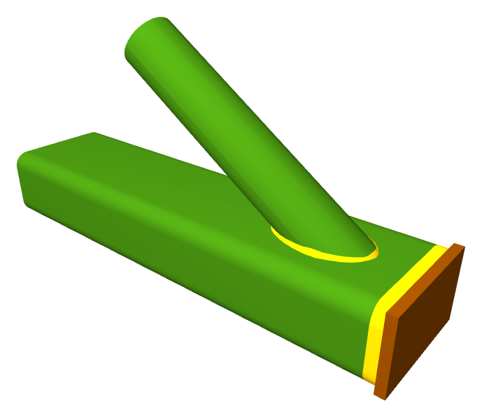
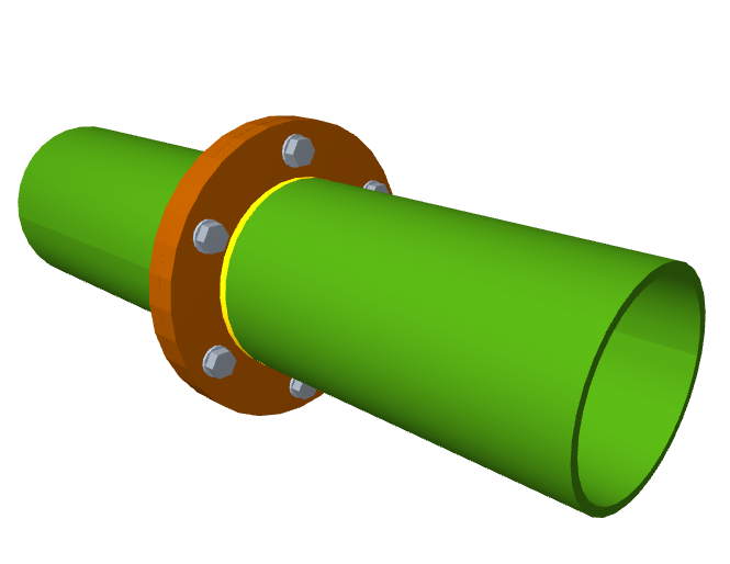
(2) The program automatically trims the plates transforming them into a circular crown whose dimensions depend on the sections which are going to be joined.
(3) In this splice connection, only two columns of bolts are provided along the longest sides of the sections to join.
Joint design of flat trusses with hollow structural sections
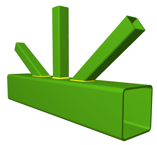
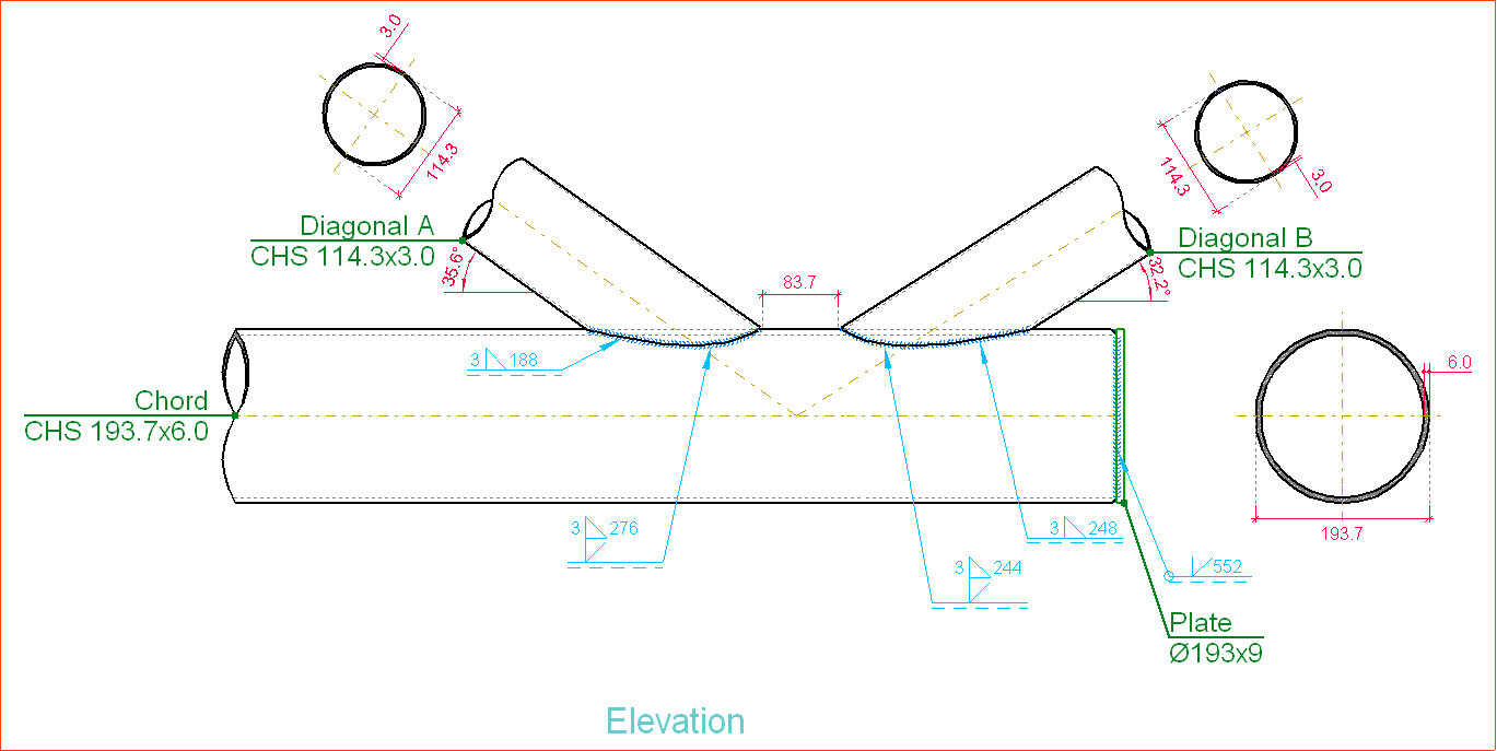
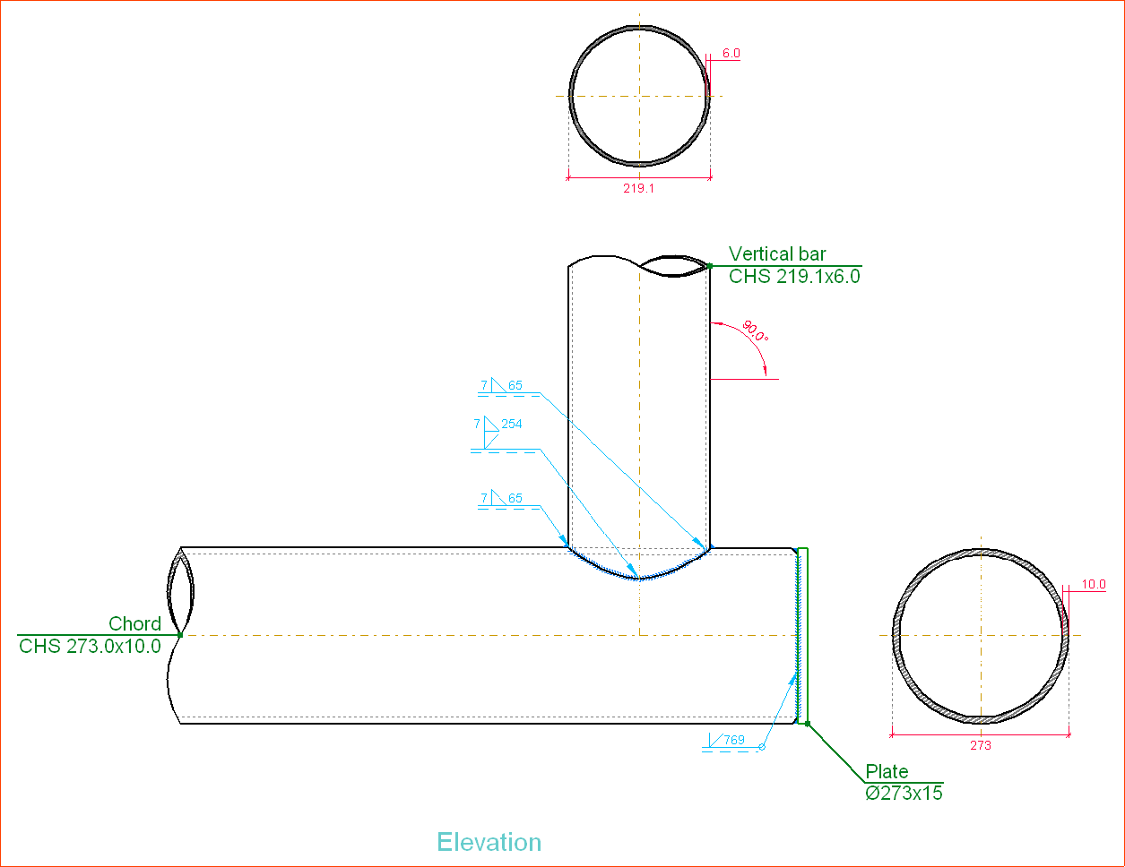
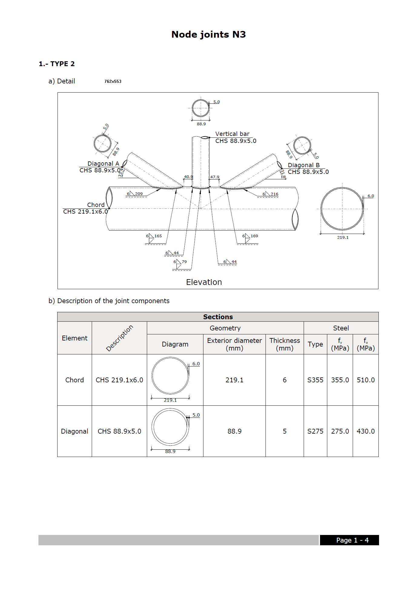
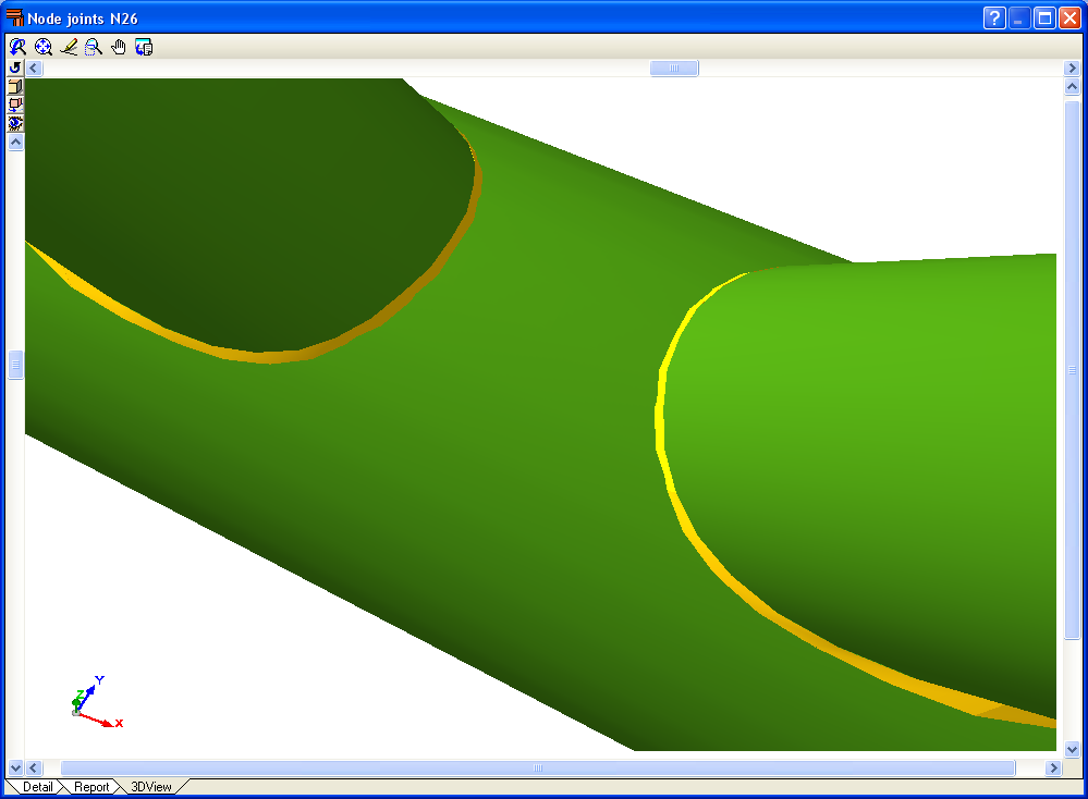
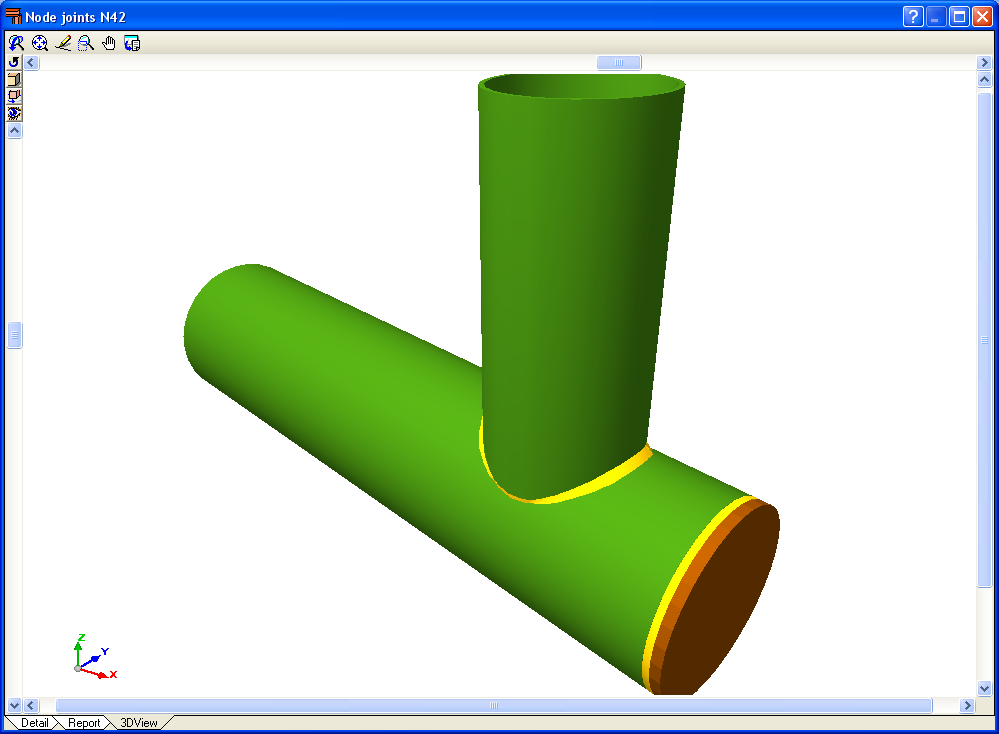
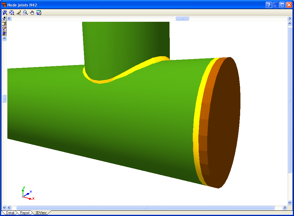
Besides all the resistance checks indicated by the codes, the program also analyses and represents the edge preparation of the tube ends to be able to weld the sections correctly.
The tubes must consist of welded sections, with the additional condition that the bar acting as the truss chord must be a continuous bar, in the case of an intermediate node.
The geometric and resistance checks carried out are detailed below:
- For circular hollow sections
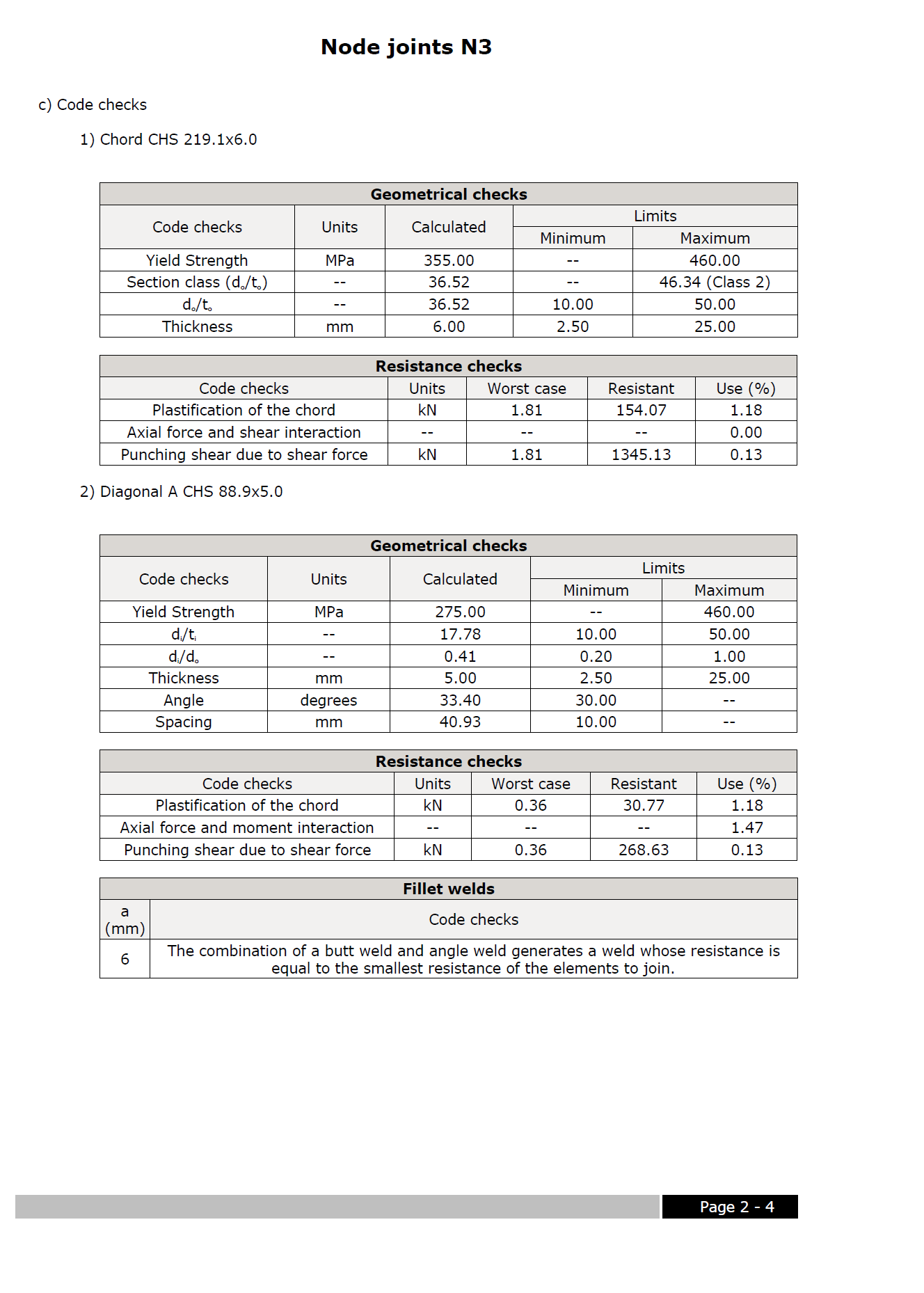
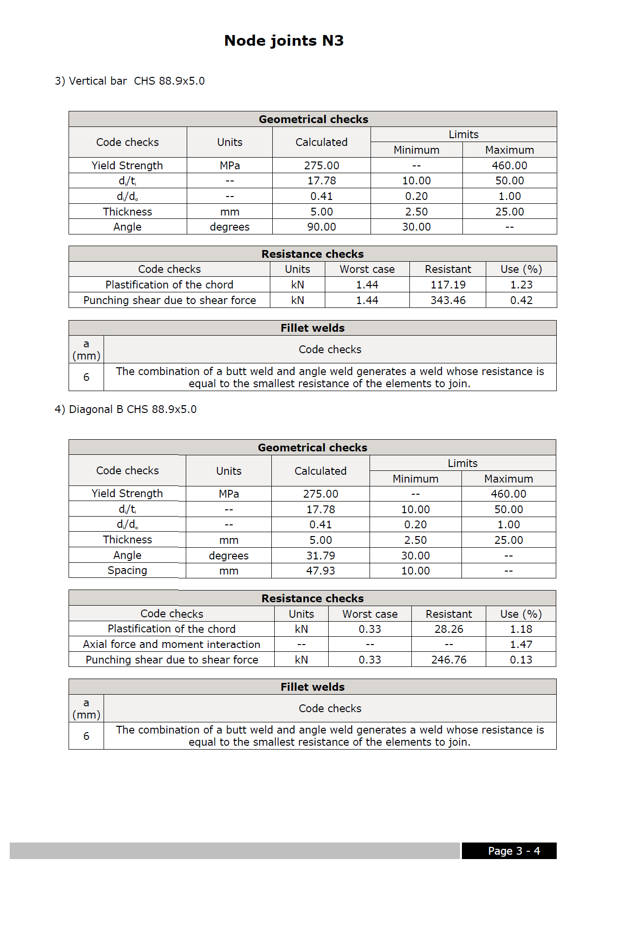
- Geometric checks carried out on joints with circular hollow sections
- For the chords
- Maximum elastic limit
- Ratio between the chord diameter and thickness
- Section class (for chords in compression)
- Minimum and maximum chord thickness
- For the remaining bars
- Maximum elastic limit
- Ratio between the bar diameter and thickness
- Section class (for bars in compression)
- Minimum and maximum bar thickness
- Minimum angle between the chord and remaining bars
- Ratio between the truss bars and chord diameter
- Minimum gaps between truss bars
- Minimum overlaps between truss bars
- For the chords
- Resistance checks carried out on joints with circular hollow sections
- Plastification of the chord surface
- Punching shear of the chord surface
- Interaction between axial force and bending moments
- Interaction between axial force and shear force of the chord
- Shear force at the chord surface in the case of overlapped bars
- The overlapped bar is checked as being the chord of the overlapping bar (for overlaps greater than the limiting overlap indicated in the code)
- Local plastification of the overlapping bar
- Geometric checks carried out on joints with circular hollow sections
- For rectangular hollow sections, square hollow sections and two channels welded in a box
- Geometric checks carried out on joints with rectangular hollow section chords
- For the chords
- Maximum elastic limit
- Section class
- Minimum and maximum chord thickness
- Ratio between the width and depth of the bar
- Ratio between the width and thickness of the bar
- Ratio between the depth and thickness of the bar
- For the remaining bars
- Maximum elastic limit
- Section class (for bars in compression)
- Minimum and maximum bar thickness
- Minimum angle between the chord and remaining bars
- Ratio between the width and depth of the bar
- Ratio between the with and thickness of the bar
- Ratio between the depth and the thickness of the bar
- Ratio between the width of the remaining bars and the width of the chord
- Minimum spacing between the remaining bars
- Minimum overlaps between truss bars
- Ratio between the width of the overlapping bar and the width of the overlapped bar
- For the chords
- Resistance checks carried out on joints with rectangular hollow section chords
- Plastification of the chord surface
- Failure of the lateral surface of the chord
- Local failure of the remaining bars considering their effective width
- Punching shear of the chord surface
- Interaction between axial force and bending moments
- Interaction between axial force and shear force of the chord
- Shear force at the chord surface in the case of overlapped bars
- The overlapped bar is checked as being the chord of the overlapping bar (for overlaps greater than the limiting overlap indicated in the code)
- Failure due to distortion in T-Y nodes for bending moments outside the plane of the truss
- Geometric checks carried out on joints with rectangular hollow section chords
Welds are designed so they have at least the same resistance as the bars that are being joined.
Combinations of different types of hollow sections in the same joint
The different types of sections resolved by the Joints V module can be combined in the same joint, ensuring the rules described below are followed:
- If the sections making up the truss chords are rectangular hollow sections, square hollow sections or two channels welded in a box; the diagonals and vertical bars can be combined at the joint with any type of hollow section that has been implemented (circular hollow section, rectangular hollow section, square hollow section or two channels welded in a box).
- f the sections making up the truss chords are circular hollow sections, the diagonals and vertical bars must also be circular hollow sections.
Joint consultation of flat trusses with hollow structural sections
Those joints that have been designed by the program may be consulted after the analysis.
CYPECAD and CYPE 3D place different coloured circles at the nodes to indicate if all, some or none of the connections of the node have been designed.
By moving the cursor close to a node containing joints that have been designed, an information box appears indicating the joint types associated with that node. Upon clicking on it, a dialogue containing three tabs appears. These tabs contain the following information:
- The construction details of the joints that have been resolved
- A report displaying the checks carried out on the joints and their takeoff
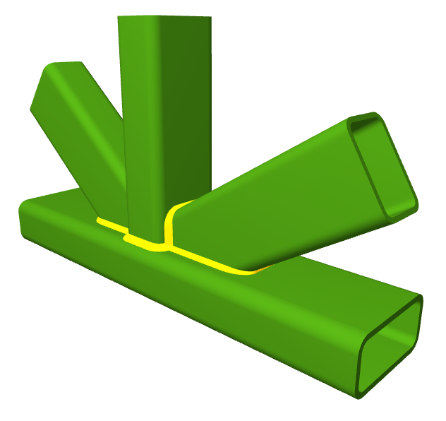
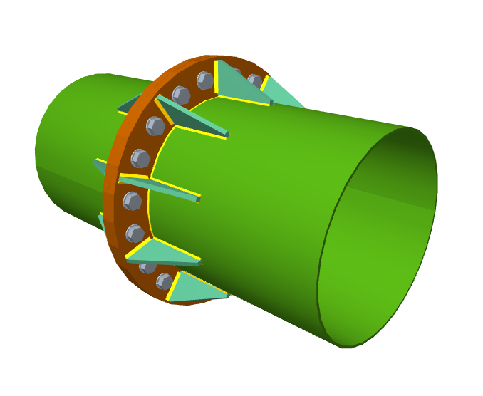
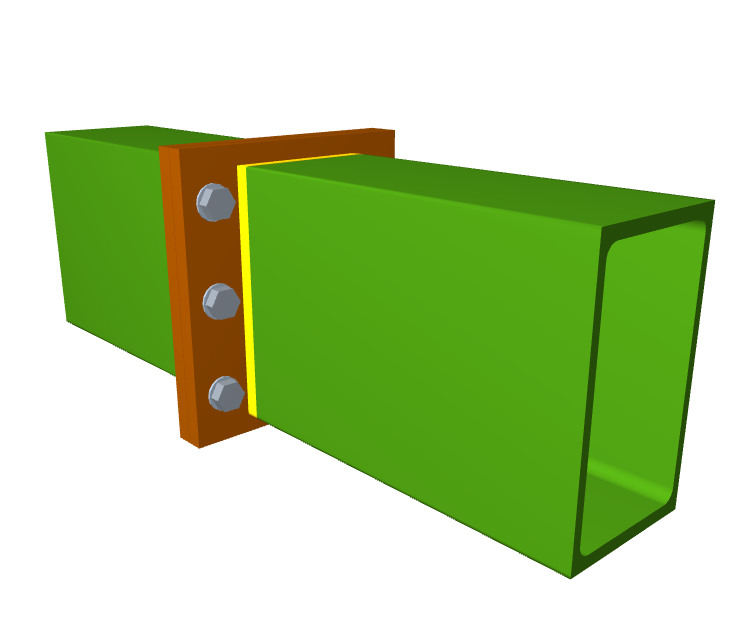
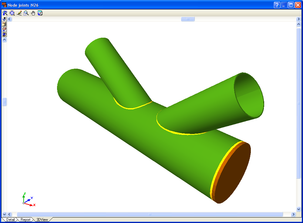
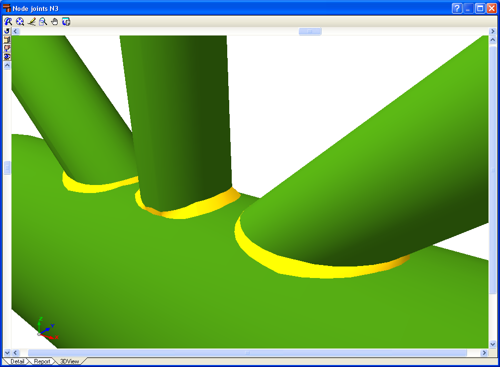
- Real 3D views of the nodes. Users can obtain a real 3D view (conical projection or isometric projection) of each node with all the connections that have been designed by the program. Elements making up the joint (bars, end plates, welds) are displayed in different colours. Users may also freely rotate and amplify the 3D views. These properties provide great help in understanding the assembly composition of the node.


Implemented design codes for the design of flat trusses with hollow structural sections
Steel code
The following codes have been implemented in CYPECAD, CYPE 3D and Integrated 3D structures of CYPECAD for the design of flat trusses with hollow structural sections:
- ABNT NBR 8800 (Brazil)
- ABNT NBR 8800:2008 (Brazil)
- ANSI/AISC 360-05 (LRFD) (USA - International)
- ANSI/AISC 360-10 (LRFD) (USA - International)
- CTE DB SE-A (Spain)
- EAE (Spain)
- Eurocode 3 EN 1993-1-8:2005 (General Document)
- Eurocode 3 NF EN 1993-1-8/NA:2007-07 (With National Application Document for France)
- Eurocode 3 NP EN 1993-1-8:2005/NA:2010 (With National Application Document for Portugal)
- Eurocode 3 UNI EN 1993-1-8:2005 (General Document adapted to Italy)
- IS 800:2007 (India)
- NTC: 14-01-2008 (Italy)
The corrections carried out by the European Committee for Standardization on Eurocode 3 (EN 1993-1-8:2005 / AC:2009) have also been implemented.
Bolt series
The available bolt series depends on the steel code used for the design. These are indicated in the table below:
| Steel codes | Prestressed bolt series | Ordinary bolt series |
|---|---|---|
| ABNT NBR 8800 (Brazil) ABNT NBR 8800:2008 (Brazil) | ASTM A307 ASTM A325 ASTM A490 ASTM A325 M ASTM A490 M ISO 4016 | ASTM A325 ASTM A490 ASTM A325 M ASTM A490 M |
| ANSI/AISC 360-05 (LRFD) (USA - International) ANSI/AISC 360-10 (LRFD) (USA - International) | ASTM A307 ASTM A325 ASTM A490 ASTM A325 M ASTM A490 M | |
| CTE DB SE-A (Spain) EAE (Spain) Eurocode 3 EN 1993-1-8:2005 (General Document) Eurocode 3 NF EN 1993-1-8/NA:2007-07 (With NAD for France) Eurocode 3 NP EN 1993-1-8:2005/NA:2010 (With NAD for Portugal) Eurocode 3 UNI EN 1993-1-8:2005 (General Document adapted to Italy) NTC: 14-01-2008 (Italy) | ISO 7411 ISO 7412 EN 14399-3, HR System EN 14399-4, HV System | ISO 4014 ISO 4017 |
| IS 800:2007 (India) | ISO 7411 ISO 7412 |
Other features
In order to access further features offered by the program, there are several modules that can be found on the “CYPECAD modules” and “CYPE 3D modules” webpages.