
Steel columns
With the “Steel columns” module, these elements can be entered into CYPECAD so that they can be designed and built up according to the code selected. The program also designs reinforced concrete columns with rectangular and circular transverse sections, although this requires the “Concrete columns” module.
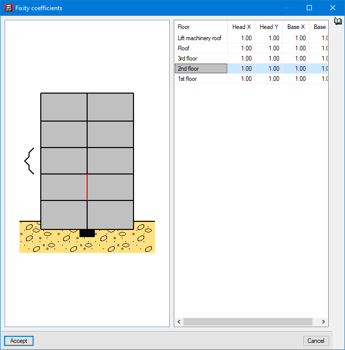
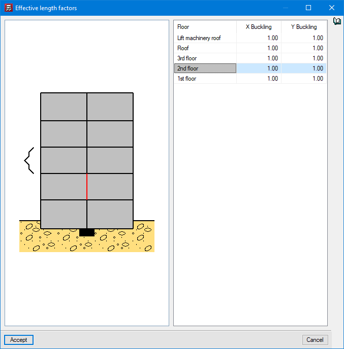
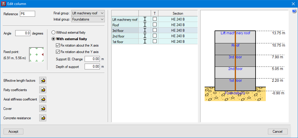
The fixity coefficients of both the base and head of each column and the effective length factors entered automatically by the program can be modified. Columns can either start on foundations (on footings, beams and foundation slabs) or they can be of the floating column type and start on any floor.
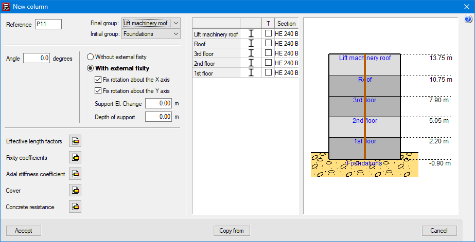
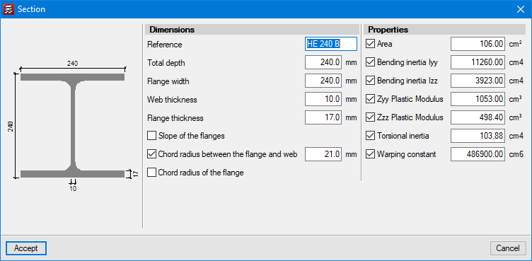
Steel sections are selected from predefined libraries in the program. CYPECAD has 33 different section libraries. Additionally, users can add their own libraries by copying existing ones or manually inserting them. Sections that do not come from a library (editable sections) can also be entered into a job. To do this, users must enter their geometric and mechanical features.
When entering data, the column’s alignment point (corners or faces) can be defined if column section height decreases.

Design options
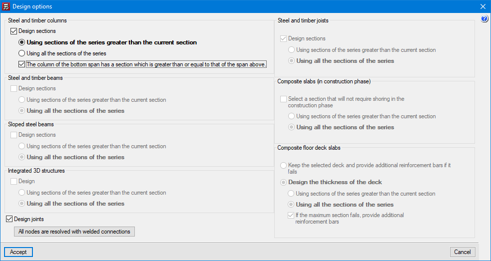
Before the analysis, the program asks users for the design options for the steel and composite elements in the job. In the case of steel columns, there is the choice of deciding whether to have them designed by the program or whether to keep those specified by the user. If users want the program to design them, they can choose between two options: the program can only use series sections greater than the one provided by the user, or it can use even lower sections as long as they comply with users’ requirements.
Results
Design analysis, reports and drawings
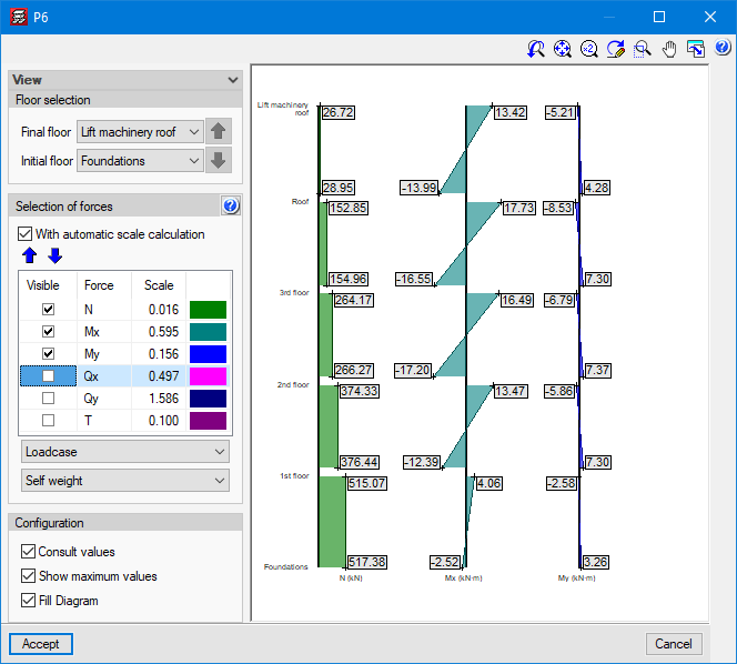
Once analysed, users can consult the force graphs of columns by simple loadcases in a dialogue box that also shows the analytical results onscreen as the cursor moves over the graphs.
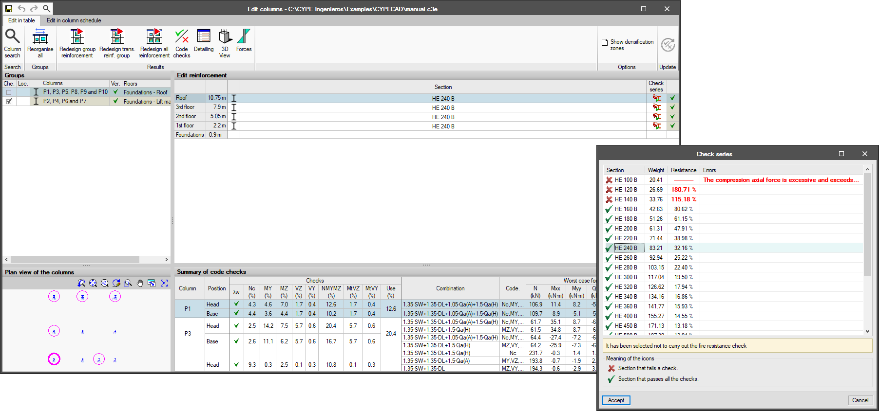
The program marks the column sections that do not comply on each floor in red. Users can visualise a window that indicates which spans have problems, the optimal section of the series (whether it is inferior, equal or superior to the one provided), the complete series of sections indicating which ones comply and which do not, and the worst-case forces for the designing of the column.
CYPECAD prepares reports of the columns’ forces, reinforcements, displacements, distortions and quantities.
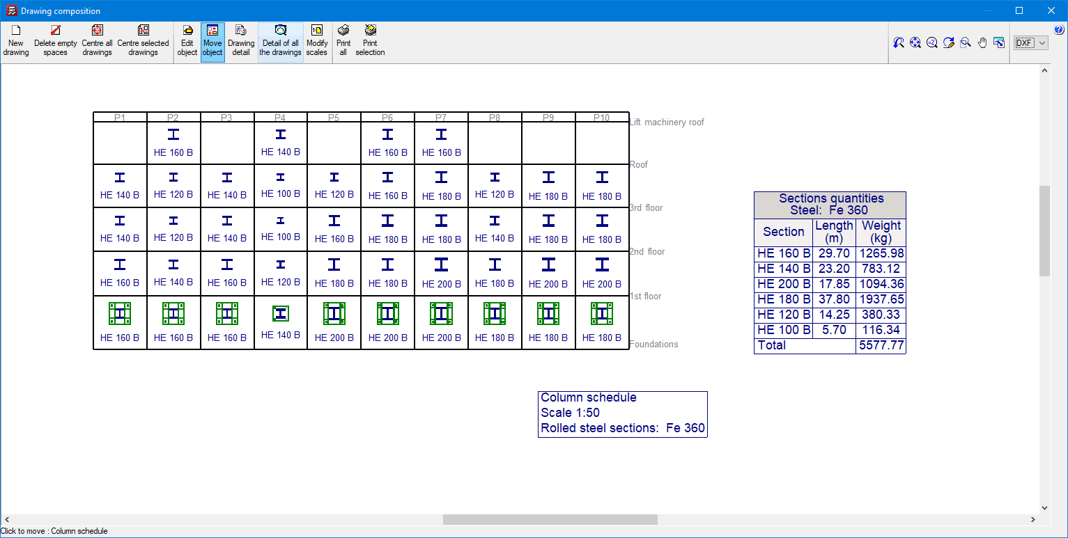
It also prepares precise drawings with a column schedule and foundation loads.


Detailed ultimate limit state check reports for steel columns
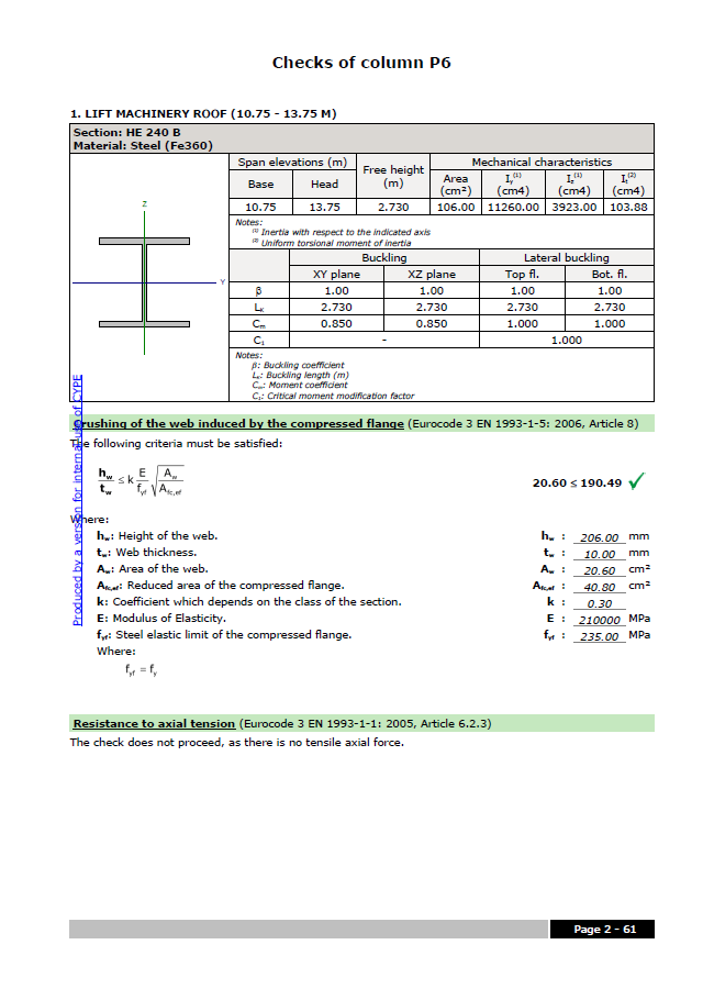
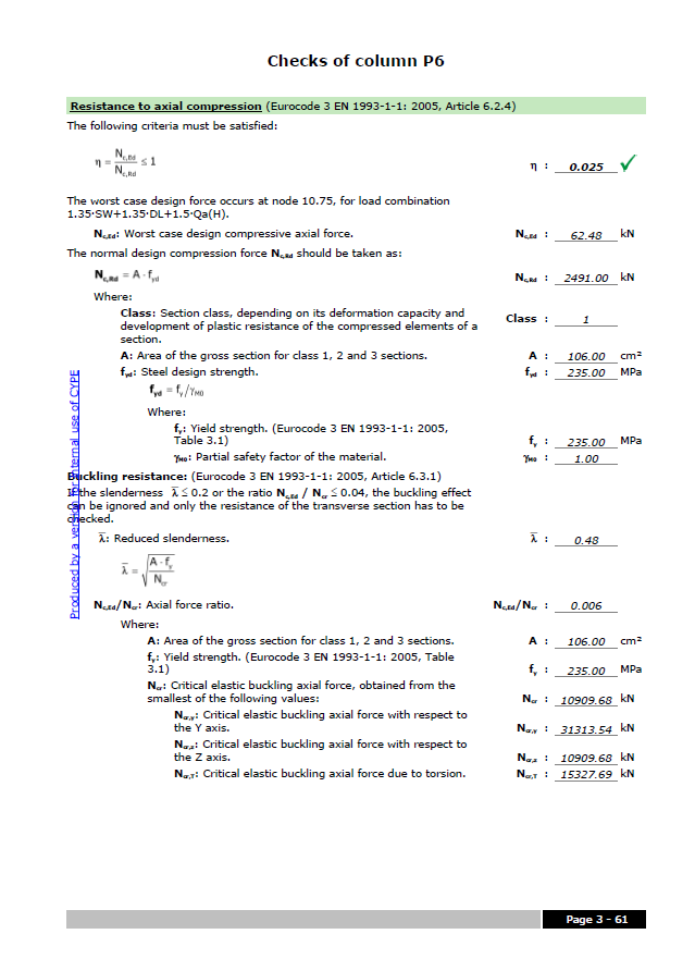
CYPECAD prepares detailed ultimate limit state check reports for rolled steel, reinforced steel and cold rolled steel columns. The ULS reports contain all the checks that the program carries out for designing steel columns. Each check refers to the code and the article required, or to the criteria that have been considered to carry out the design. The details in the ULS reports make them essential documents with which users can verify, justify and optimise the design of analysed structural elements.
The level of detail in these reports also gives them a didactic feature that allows users to be aware of all the checks that a section is subject to.
More information about these documents (CYPE programs that generate ULS reports, how to obtain them, codes for which they can be generated, etc.) can be found at Detailed ultimate limit state check reports.
CYPECAD versions
CYPECAD is available in its unlimited version and also in two limited versions called LT30 and LT50, which contain the same tools and module acquisition possibilities, but have the following conditions:
CYPECAD LT50:
- Fifty columns.
- Four floor groups (Floor group: floors which are the same and consecutive).
- Total of five floors.
- Walls: one hundred linear metres. Feature available with the Building walls module.
CYPECAD LT30:
- Thirty columns.
- Four floor groups (Floor group: floors which are the same and consecutive).
- Total of five floors.
- Walls: one hundred linear metres. Feature available with the Building walls module.
Integrated 3D structures of CYPECAD (also LT50 and LT30) is not technically a module. To define these 3D structures in CYPECAD, users must also have the required permits to use CYPE 3D in their user license and, optionally, modules that are exclusive to CYPE 3D.
Other features
In order to access further features offered by the program, there are several modules that can be found on the "CYPECAD modules" and "CYPE 3D modules" webpages.