As of the 2016.m version, users can export to the 21.1 version of Tekla Structures from CYPE 3D.


As of the 2016.m version, users can export to the 21.1 version of Tekla Structures from CYPE 3D.
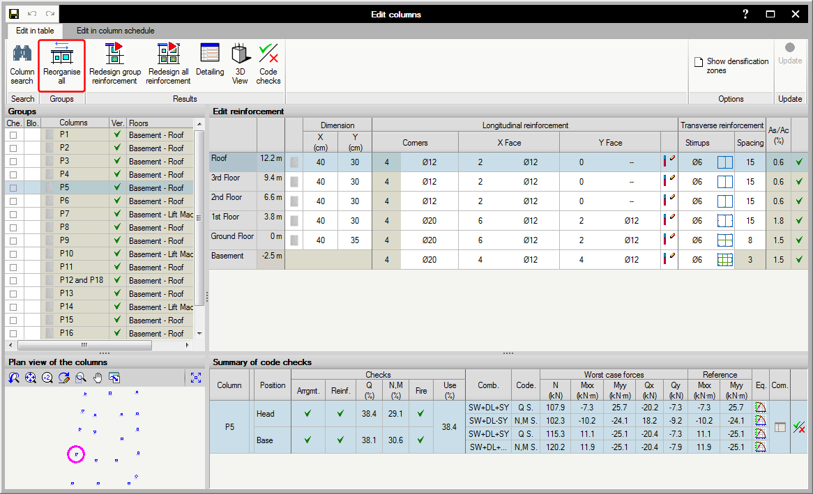
The 2016.k version of the advanced column editor includes a button to reorganise columns in alphanumerical order. This order is that generated by default after analysing the job.
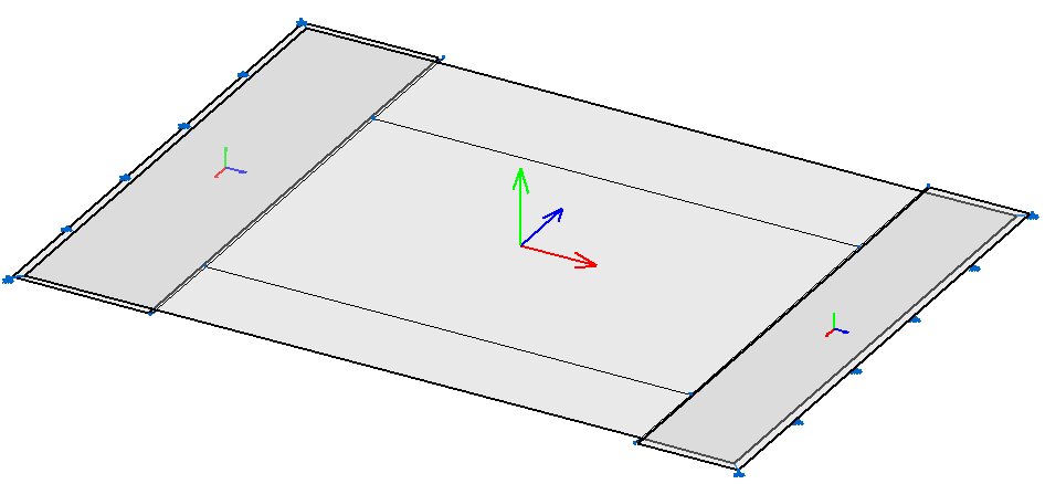
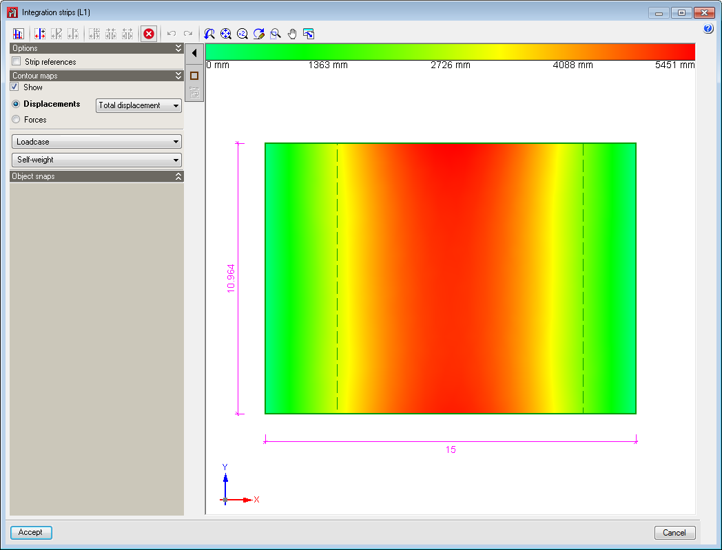
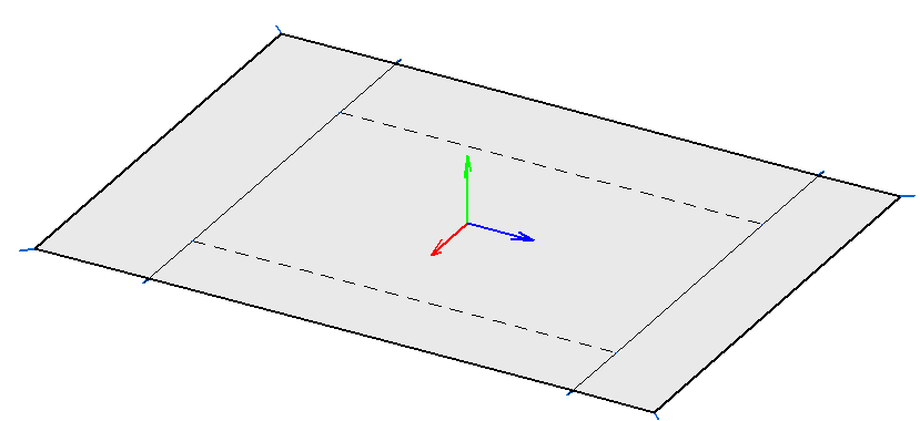
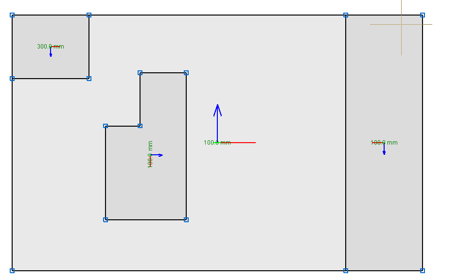
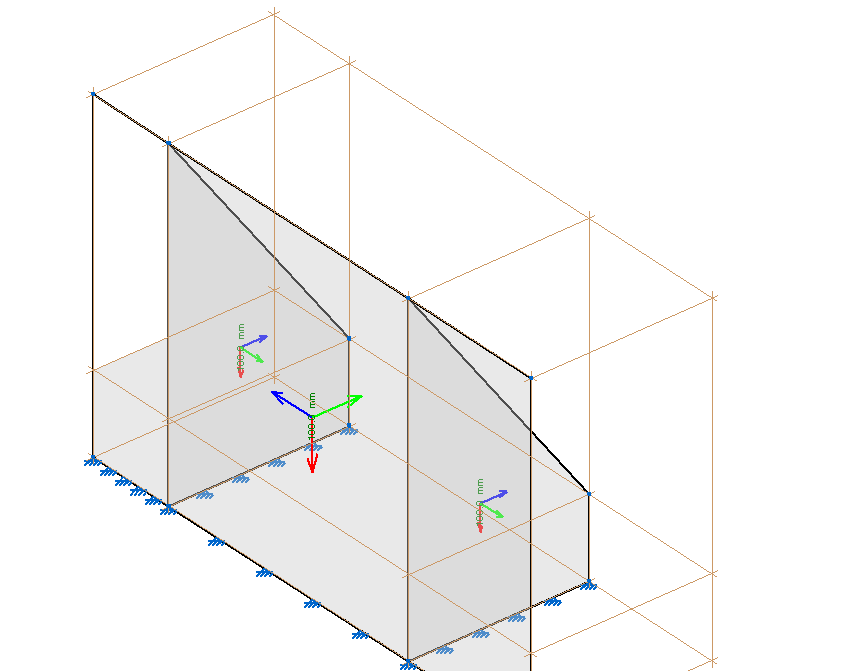
Integration strips can be drawn when shells contain other shells. Their axes do not necessarily have to coincide; the program transforms the forces from the reference system of the contained shells to those of the container shell.
The zone corresponding to the contained shells are marked with a discontinuous rectangle.
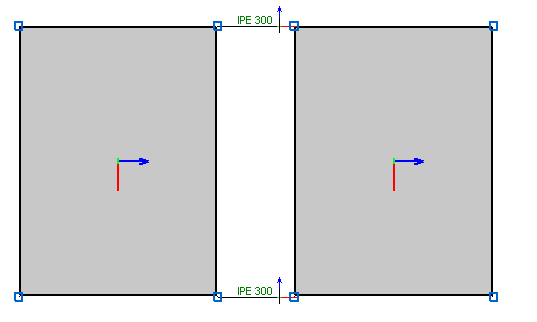
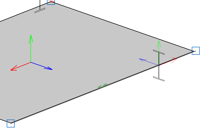
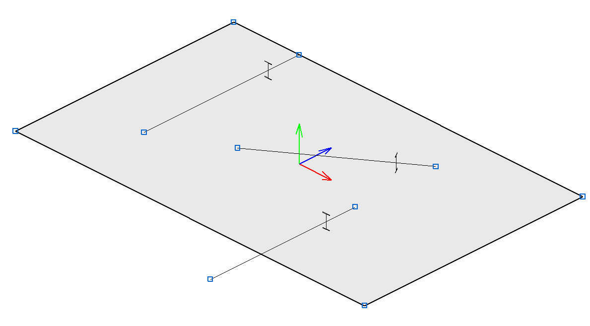
This option is located in the Bar menu. It allows users to indicate whether a bar, if it crosses a shell, is to be connected to it or not. It does not affect the Shell-Bar interaction at an edge. Bars that are not connected to shells are displayed with a discontinuous line.
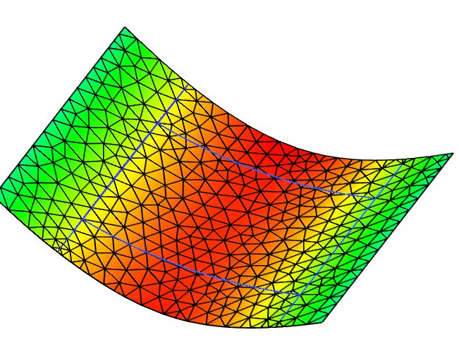
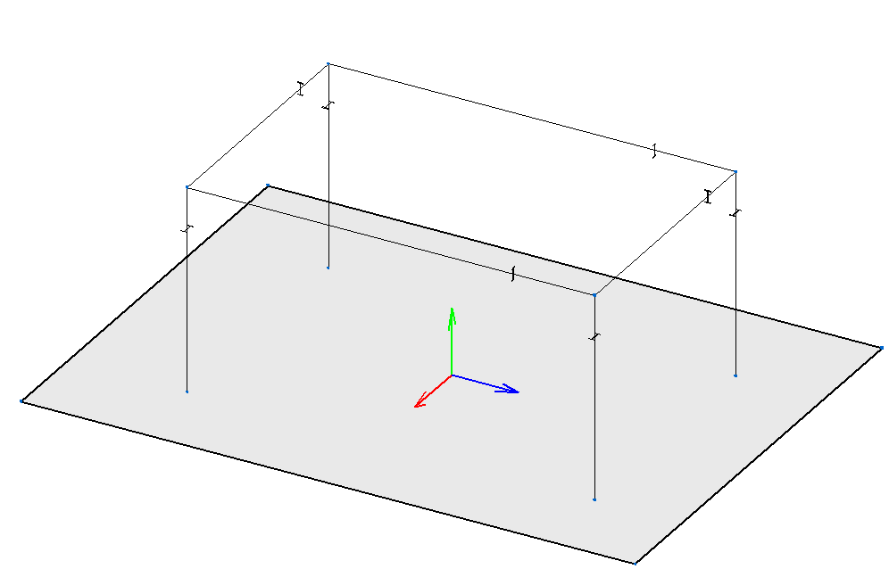
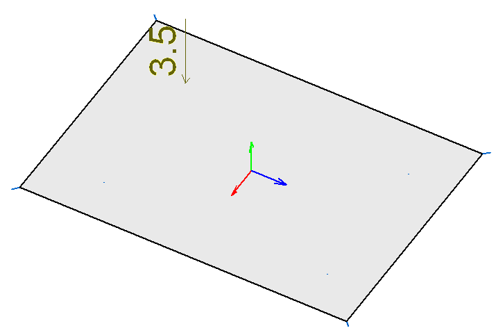
As of the 2015.1.c version, users could define shell elements in CYPE 3D. Shells connect to one another and to the rest of the structure in an explicit manner via their edges, allowing for only the following interactions to occur:
As of the 2016.1.g version, the following additional interactions are permitted:
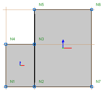
Under no circumstances can one shell be completely overlapped by others.
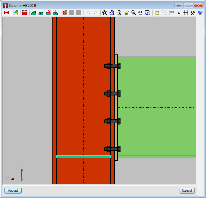
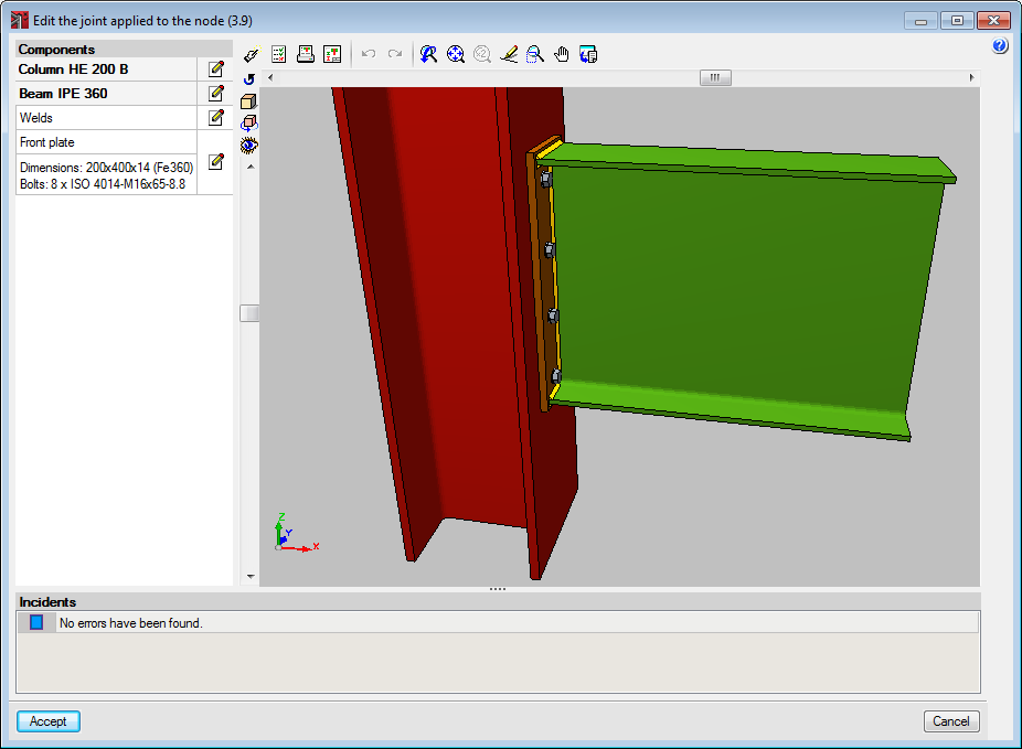
In previous versions, connections fixed to column or beam flanges, welded or bolted, required web stiffeners.
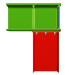
As of the 2016.a version, these connections can be defined without stiffeners. This option is available only to check the connection. If the connection is re-designed, stiffeners will be provided. Users has the option to delete the designed stiffeners and check the connection without the stiffened web. Stiffeners associated with a moment reinforcement in the connection to the web of the main section are required and cannot be eliminated.
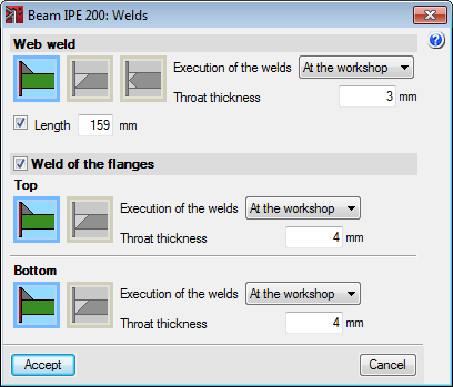
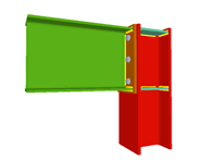
In versions earlier than the 2016.a version, the type of weld applied could not be edited. The welds are generally angle welds (except in connections with circular hollow sections and anchorage bolts).
As of the 2016.a version, the type of weld can be edited. Users can choose amongst:
The welds will be represented on the plans with their corresponding symbols.