
Introduction
CYPECAD carries out the design, analysis, and sizing of structures for building and civil works which are subject to vertical and horizontal forces as well as fire exposure.
More information about seismic analyses carried out by CYPECAD can be found on this webpage.
More general information about this program can be found on the CYPECAD website.
Design load analysis
Before specifying the features of the seismic analysis that CYPECAD can carry out, it is worth noting the analysis of vertical and horizontal design loads that the program performs.
A summary of this information can be found in the “Design load analysis” section of CYPECAD’s main information page.
Detailed information on this topic can be found in the “CYPECAD - Calculations manual”. This manual can be accessed from the main menu of CYPE programs or from the “Help” drop-down menu in CYPECAD.
Seismic analysis
The seismic analysis is carried out by means of a modal spectral analysis that solves each modal as a loadcase and performs modal expansion and modal combination in order to obtain forces.
The “CYPECAD - Calculations manual” can be accessed from the main menu from any CYPE program or from the “Help” drop-down menu in CYPECAD, where extensive information about seismic analysis carried out by CYPECAD can be found.
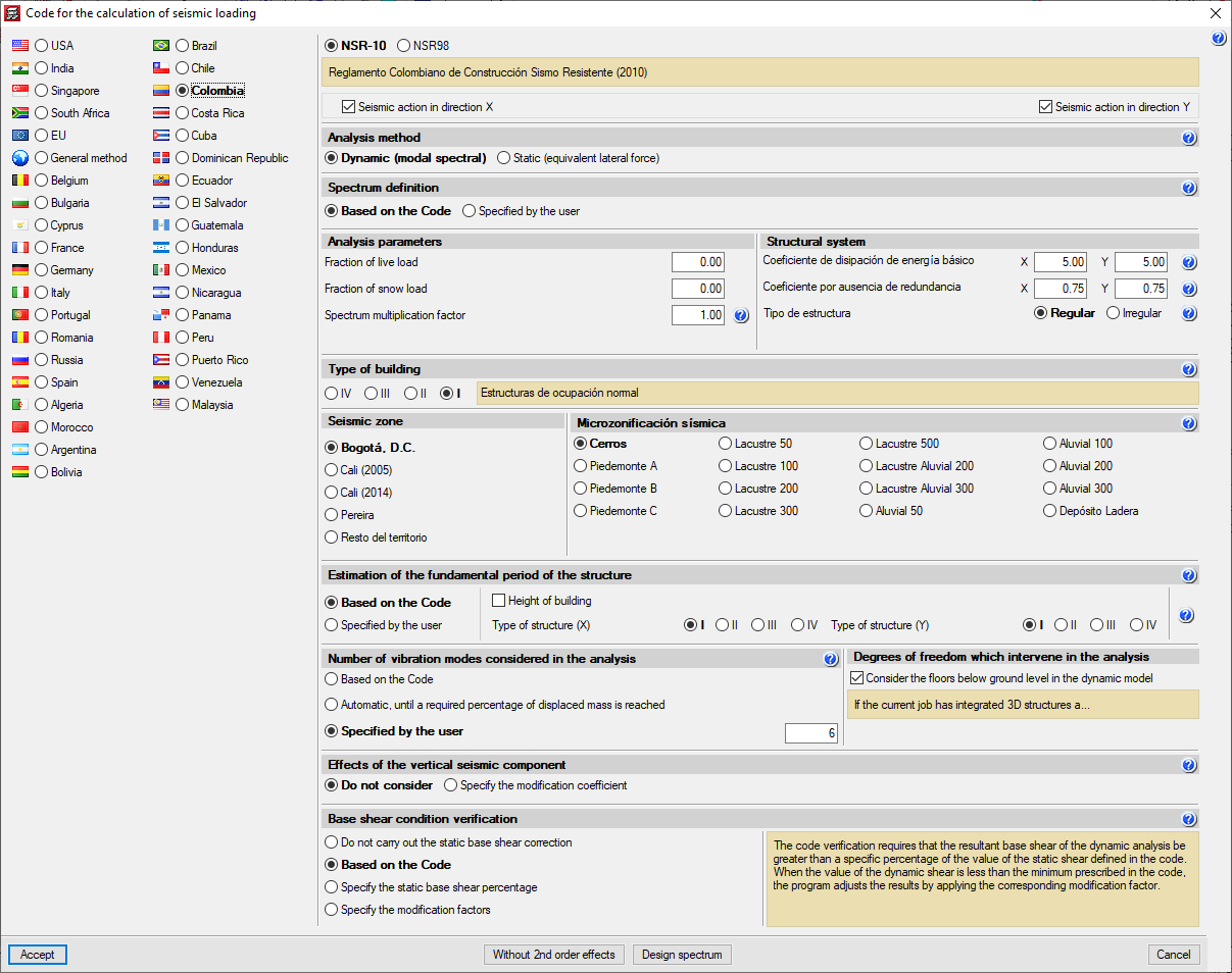
The selection of the code for carrying out seismic analysis in CYPECAD appears in the “General data” window, more precisely, in the “Load selection” section. On the “CYPECAD. General data, and analysis and general options” page there is information on how to access this window.
The codes that can be used can be consulted on the “Codes included in the user license” web page.
Some important aspects of the seismic analysis carried out by CYPECAD are explained in the following sections.
Effect of non-structural construction elements on buildings’ seismic behaviour
Considering the effect of the non-structural construction elements (external walls and partitions) on a building’s behaviour when facing seismic actions is of vital importance, especially when there are open floors or floors with partitions and external walls that are less rigid than the rest of the floors.
CYPECAD allows the effect of non-structural elements during an earthquake to be considered in two ways:
- By means of amplifying forces in open floors or those with less rigid partitions compared to the rest of the floors
Approximate method. - By means of a dynamic analysis of buildings subjected to seismic actions that include the effect of non-structural construction elements
Accurate analysis developed by CYPE with the collaboration of the “International Centre for Numerical Methods in Engineering (CIMNE)” from the “Polytechnic University of Catalonia (UPC),” and included in the “Interaction of the structure with the construction elements” module (in order to be used, the module must be included in the user license).
Seismic analysis with force amplification in open floors or those with less rigid partitions compared to the rest of the floors
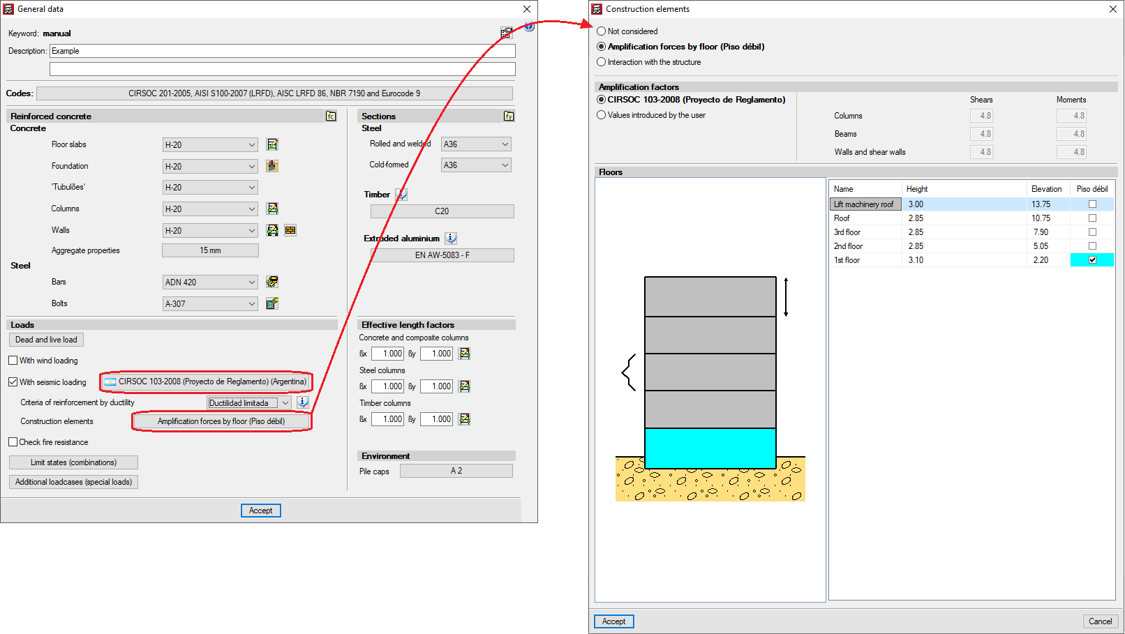
Some codes require the absence or reduction of stiffness of the partitions and external walls on certain floors, by applying moment and shear amplification factors for columns, beams, walls and shear walls, on the floors with less stiffness than others when faced with horizontal displacements caused by seismic action. For example, code IS 13920 (India) -Soft Storey- or the code CIRSOC 103-2008 (Argentina) -Piso débil. Naturally, the tendency of the codes that do not consider these effects should focus on addressing them.
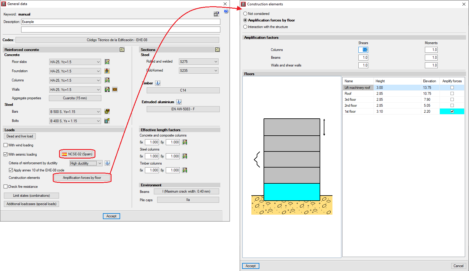
CYPECAD allows users to introduce the moment and shear amplification factors for columns, beams, walls and shear walls, on the desired floors, regardless of the selected code. For this purpose, the Amplification forces by floor option has been added to the General data window (Project menu > General data). By activating this option, a window with the same name will open. If the selected code considers the effect of the reduced stiffness of floors with weaker partitions, the program will display the corresponding moment and shear amplification factors onscreen so that users can select the floors where they wish to apply them. Users also can indicate the factors they desire. If the selected code does not consider these effects, the program will allow users to introduce the desired amplification factors to the floors they select.
This method for considering the effect that the absence of partitions and external walls has on certain floors when faced with seismic action is an approximation to the reality of the behaviour of the building.
CYPECAD has a software tool that takes a more accurate look at the influence that the distribution of partitions and external walls has on the building: the “Interaction of the structure with the construction elements” module which is summarised in the following section.

Interaction of the structure with the construction elements
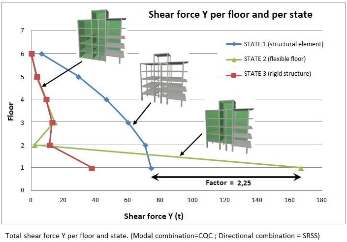
CYPECAD has a software tool that allows dynamic analysis of buildings under seismic actions including the effect of the nonstructural construction elements used in the external walls and partitions of a building and considers various models of building behaviour corresponding to different situations or states of these elements.
The external walls and partitions of the buildings are considered as ‘nonstructural’ elements, however, during an earthquake, they provide the structure with stiffness, modifying the distribution and magnitude of the forces caused by the seismic action. For example, when there is an uneven distribution between the floors of the stiffnesses associated with the external walls, the horizontal forces have a greater impact on the columns of the floors with less stiffness, causing a high magnitude of shear forces in the columns. If the columns are not properly designed, the forces could cause their brittle failure, which would endanger the stability of the building and even lead to its collapse.
This module has been developed by CYPE, with the collaboration of the International Centre for Numerical Methods in Engineering (CIMNE) from the Polytechnic University of Catalonia (UPC), financed by the Centre for the Development of Industrial Technology (CDTI) and co-financed by the European Regional Development Fund (ERDF).
There are currently no software tools on the market for the structural analysis of buildings that include the possibility of considering external walls and partitions in a simple way, despite the fact it has been proved that they have direct consequences on stability, stiffness and building safety in the event of an earthquake. Since this CYPECAD module does include them, keeping computation times at an admissible value, their incorporation in building projects will increase their quality and the safety of occupants, thus avoiding major losses, both material and human, following an earthquake.
More information can be found on the “Interaction of the structure with the construction elements” webpage.
Seismic design criteria by capacity
Seismic design criteria by capacity for supports and concrete beams
When a seismic analysis is carried out in CYPECAD, the program considers design criteria by the capacity of certain codes.
- For concrete supports, the program considers the design criteria for bending and shear capacity of the following codes:
- EHE‑08 - Anejo 10 (Spain)
- NCSE‑02 (Spain)
- IS 13920: 1993 (India)
Only shear capacity design criteria are available.
- ACI 318M‑08 (USA)
- NSR‑10 (Colombia)
- 1997 UBC (USA)
- CIRSOC 103‑2005 (Argentina)
With the combination of concrete regulation CIRSOC 201‑2005, and the seismic regulations CIRSOC 103‑2008 or CIRSOC 103‑1991.
- NTE E.060: 2009 (Peru)
- NEC -11 (Ecuador)
- PS 92 (France)
- PS 92 (version révisée 2010) (France)
- RPA 99/v 2003 (Algeria)
- RPS 2000 (Morocco)
- RPS 2011 (Morocco)
- For concrete beams, the program considers the shear capacity design criteria for the following codes:
- EHE‑08 - Anejo 10 (Spain)
- NCSE‑02 (Spain)
- IS 13920: 1993 (India)
- ACI 318M-08 (USA)
- NSR‑10 (Colombia)
- 1997 UBC (USA)
- CIRSOC 103‑2005 (Argentina)
With the combination of the concrete code CIRSOC 201‑2005, and the seismic codes CIRSOC 103‑2008 or CIRSOC 103‑1991.
- NTE E.060: 2009 (Peru)
- NEC -11 (Ecuador)
- PS 92 (France)
- PS 92 (version révisée 2010) (France)
- RPA 99/v 2003 (Algeria)
- RPS 2000 (Morocco)
- RPS 2011 (Morocco)
The design criteria by capacity are specified in the detailed reports of beam and concrete beam Ultimate Limit States.
In order for CYPECAD to take into account the capacity design criteria of the indicated earthquake codes, each one must be compatible with the concrete code selected in the job and allow the use of advanced beam and column editors. These compatibilities can be consulted in the “Available codes for the advanced beam editor” section on the “Concrete beams” page.
Seismic design criteria by capacity for slabs
The capacity checks carried out by CYPECAD automatically include the geometric and mechanical features of concrete columns and beams and, optionally, those of the slabs supported by beams reaching a column.
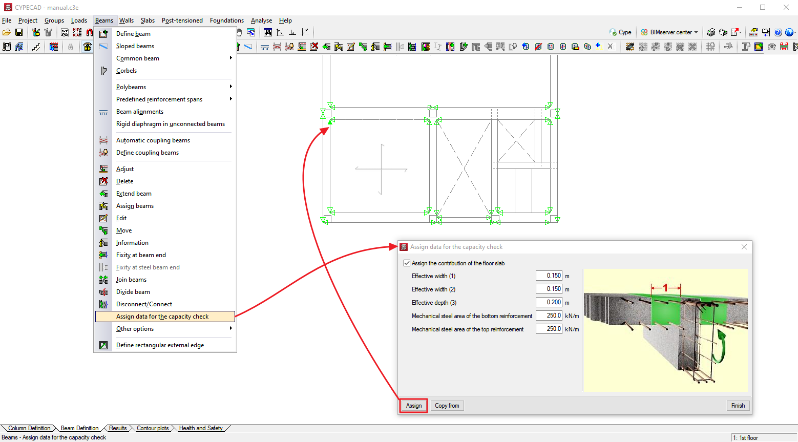
In order to define the geometric and mechanical features of these slabs, for the purpose of the capacity checks for concrete beams and columns, the “Assign data for the capacity check” option has been added (Beam definition tab > Beams/walls menu).
The aforementioned option will only be visible if a seismic analysis is carried out with a code for which the program includes capacity design criteria.
When this option is activated, a window appears where users can define the following data:
- Positive effective width
- Negative effective width
- Effective depth
- Mechanical steel area of the bottom reinforcement
- Mechanical steel area of the top reinforcement
Users can freely assign them to each one of the sides and edges of the beams reaching the columns. This allows the contemplation of cases in which the slabs have different geometric or mechanical features on each side of the beams or those in which there is not a slab on each side of the beam.
To identify each one of the sides and edges of the beams which have been assigned data for the capacity checks, the program draws small magenta triangles in the zones that are displayed when the “Assign data for the capacity check” option has been selected. The triangles will be green in the zones where the slab features have not been assigned, in which case, the dimensions and ratios of the slab will not be included in the capacity checks of concrete columns and beams.
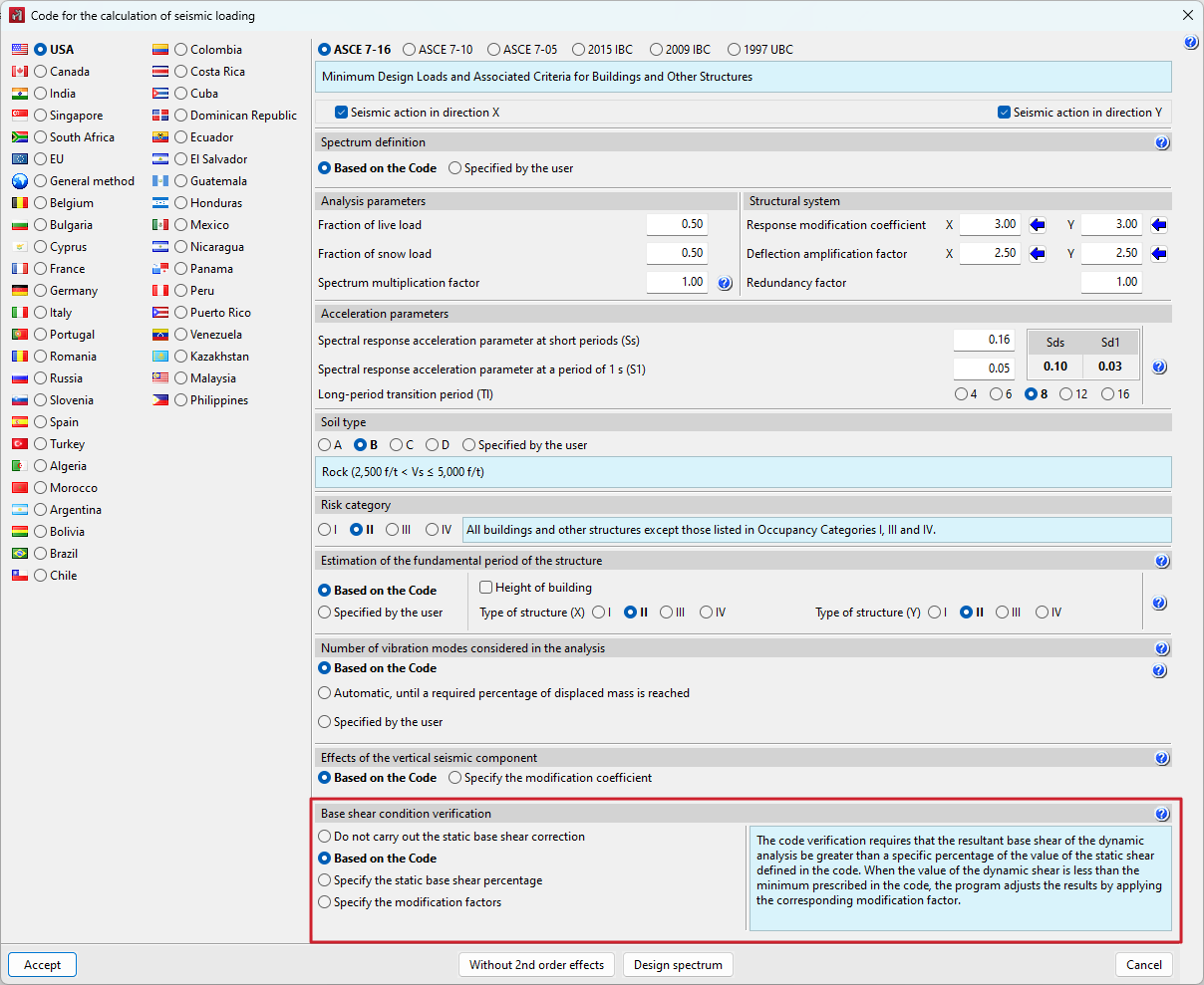
Base shear correction for seismic analysis using the dynamic analysis method
Certain seismic codes require the minimum basal shear condition to be fulfilled when applying the dynamic modal spectral method for seismic action analysis. The base shear check is implemented into CYPECAD and CYPE 3D for the following codes:
- 2009 IBC (USA)
- 2015 IBC (USA)
- 2011 PRBC (Puerto Rico)
- ASCE 7- 05 (USA)
- ASCE 7- 10 (USA)
- ASCE 7- 16 (USA)
- CFE 2008 (México)
- CFE 2015 (México)
- CIRSOC 103 - 2008 (Argentina)
- CIRSOC 103 - 2013 (Argentina)
- CIRSOC 103 - 2018 (Argentina)
- CHOC - 04 (Honduras)
- CHOC - 08 (Honduras)
- COVENIN 17561:2001 (Venezuela)
- CRP - 2003 (Puebla - México)
- GBDS - 2020 (Bolivia)
- IS 1893 (Part 1): 2002 (India)
- IS 1893 (Part 1): 2016 (India)
- NBDS - 2023 (Bolivia)
- NBR 15421:2006 (Brasil)
- NC 46:1999 (Cuba)
- NC 46:2017 (Cuba)
- NCh433.Of1996 Mod.2009 (Dºnº61. de 2011) (Chile)
- NEC - 11 (Ecuador)
- NEC – SE – DS 2014 (Ecuador)
- Norma Técnica E.030 2003 (Perú)
- Norma Técnica E.030 2014 (Perú)
- NSCP 2015 (Filipinas)
- NSE - 10 (Guatemala)
- NSE - 18 (Guatemala)
- NSE - 18 (Actualización 2020) (Guatemala)
- NSR‑10 (Colombia)
- NSRM - 2021 (Managua - Nicaragua)
- NTC-2004 (Ciudad de México - México)
- NTC-2017 (Ciudad de México - México)
- NTC-2020 (Ciudad de México - México)
- NTC-2023 (Ciudad de México - México)
- NTC - 97 (Guadalajara - México)
- NTDS - 1997 (El Salvador)
- R-001 2011 (República Dominicana)
- REP - 04 (Panamá)
- REP - 2014 (Panamá)
- REP - 2021 (Panamá)
- RPA 99/v 2003 (Argelia)
- RNC - 07 (Nicaragua)
- RPS 2011 (Marruecos)
- RPS 2000 (Marruecos)
- SANS 10160-4:2011 (Sudáfrica)
- TBDY 2018 (Turquía)
| More information: |
|---|
| A wide range of codes included in CYPE's programs can be found at this link. |
The value of the total dynamic shear at the base (Vd), obtained after carrying out the modal combination (CQC), for any of the analysis directions, cannot be below a certain limit value. This value is a percentage (α) of the base shear of the structure analysed using the static method (Vs). Thus, the following condition should be met: 
If the condition of the minimum shear base is not met, the results of the dynamic analysis must be adapted according to the following factor: 
The adaption covers all dynamic analysis results, including displacements, distortions, forces in floors, shear floors, base shears and forces in elements.
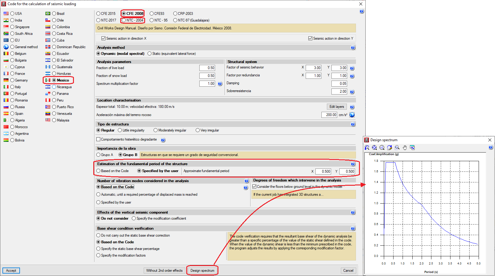
Fundamental period of the structure with user values
Certain seismic codes allow two ways of calculating the value of the Fundamental period of the structure (used to analyse the base shear). The codes implemented into CYPECAD that allow this option are:
- CFE 2008 (Mexico)
Manual de Diseño de Obras Civiles. Diseño por Sismo. - COVENIN 17561:2001 (Venezuela)
Norma Venezolana COVENIN 1756-1:2001. Edificaciones sismorresistentes. - NC 46:1999 (Cuba)
Construcciones sismo resistentes. Requisitos básicos para el diseño y construcción. - NEC 11 (Ecuador)
Norma Ecuatoriana de la Construcción. Capítulo 2.- Peligro sísmico y requisitos de diseño. - Norma Técnica E.030 (Peru)
Norma Técnica E.030 Diseño Sismorresistente. - NSR-10 (Colombia)
Reglamento Colombiano de Construcción Sismo Resistente (2010). - NTC 2004 (México)
Normas Técnicas Complementarias para Diseño por Sismo.
With these codes, the value of the fundamental period of the structure can be indicated in CYPECAD in the following two ways:
- Based on the code
- User-defined
Either of the two options can be selected in the Estimation of the fundamental period of the structure in the Code for the calculation of seismic loading window (Project menu > General data > select the “With seismic loading” option in the “Loads” section > select one of the aforementioned codes).
The value of the fundamental period of a building must be obtained from the properties of its seismic resistance system, in the direction being considered, following the principles of structural dynamics. Alternatively, the majority of seismic codes allow the use of other procedures to estimate the fundamental period:
- In accordance with empirical formulas provided in its articles.
- In accordance with other methods, as long as these are adequately supported, either analytically or experimentally.
The estimated fundamental period is applied in the analysis of the static shear at the base of the building (baseline shear) to adjust the dynamic results to the minimum prescribed design code values in the case of applying the dynamic method and to generate the equivalent static lateral forces if the static method is applied.
The values indicated by the codes are limits that can be used when lacking other more accurate data. If users have fundamental period values that are more suitable for their structure (calculated by standard methods or by software tools such as CYPECAD that analyse the fundamental period of the structure in each direction - its values can be consulted after the analysis in the “Justification of seismic action” report: Files menu > Print Job data report) they can specify them by selecting the User specified factors option located in the Code for the calculation of seismic loading window.
User-specified seismic spectrum
For certain seismic codes included in CYPECAD, the program allows users to specify a personalised seismic spectrum different to the one specified in the code.
A design spectrum must be defined to perform a seismic analysis of the structure. Each earthquake-resistance code provides the criteria to be followed within a certain territory to consider seismic action in the project. Nonetheless, CYPECAD and CYPE 3D allow designers to adopt criteria different to that established in the code at their own risk. For certain earthquake codes, both programs offer two procedures for defining the spectrum that will be used to carry out the seismic analysis of the structure. The design seismic spectrum can be:
- Calculated as specified in the applicable seismic code.
- User-specified based on their own considerations.
The seismic codes that CYPECAD and CYPE 3D currently allow personalised spectrums to be designed for are:
- NCh433.Of1996 Mod.2009 (Dºnº61. de 2011) (Chile)
Norma Chilena Oficial Diseño Sísmico de Edificios (Incluye modificaciones del decreto nº 61 (V. y U.) de 2011). - NEC-SE-DS 2014 (Ecuador)
Norma Ecuatoriana de la Construcción. Peligro sísmico. Diseño sismo resistente. - NEC -11 (Ecuador)
Norma Ecuatoriana de la Construcción. Capítulo 2.- Peligro sísmico y requisitos de diseño. - Norma Técnica E.030 (Peru)
Norma Técnica E.030 Diseño Sismorresistente. - NSR - 10 (Colombia)
Reglamento Colombiano de Construcción Sismo Resistente (2010)
This possibility for more seismic codes will be implemented in upcoming versions.
Codes included in the user license
Depending on the country from which the licensee has acquired the license, each program will only activate the implemented design codes corresponding to that country. More information about this aspect and the possibility of acquiring additional codes is available under Programs and codes included in the user license.
CYPECAD versions
CYPECAD is available in its unlimited version and also in two limited versions called LT30 and LT50, which contain the same tools and module acquisition possibilities, but have the following conditions:
CYPECAD LT50:
- Fifty columns
- Four floor groups (Floor group: floors which are the same and consecutive)
- Total of five floors
- Walls: one hundred linear metres
CYPECAD LT30:
- Thirty columns
- Four floor groups (Floor group: floors which are the same and consecutive)
- Total of five floors
- Walls: one hundred linear metres
Integrated 3D structures of CYPECAD (also LT50 and LT30) is not technically a module. To define these 3D structures in CYPECAD, users must also have the required permits to use CYPE 3D in their user license and, optionally, modules that are exclusive to CYPE 3D.