As of the 2016.a version, CYPE 3D analyses, designs and checks reinforced concrete beams and columns; and checks composite steel and concrete columns. It also provides reinforcement and U.L.S. check reports for columns, reinforcement and U.L.S. and S.L.S. check reports for beams, the column schedule and column details drawings and beam details drawings.
All the options that have been mentioned in relation with reinforced concrete columns and composite columns are available for the design codes implemented in the Advanced column editor and those in relation with reinforced concrete beams are available for the design codes implemented in the Advanced beam editor.
Columns and beams are defined as being structural element types in the CYPE 3D model when they are introduced. As of the 2016.a version, CYPE 3D allows users to define 4 types of structural elements: Generic, Tie, Column and Beam.

For the program to process an element as a column or beam, it must be introduced as a column or beam or have been assigned the corresponding structural type beforehand.
Reinforced concrete columns and beams are used mainly in building structures. Building structures are fundamentally vertical, divided into floors and composed of frames. As of this version, CYPE 3D incorporates levels and grids. Levels allow for space to be divided by horizontal planes at different heights, which allows for work zones, equivalent to floors, to be defined, and so allowing work with beam-type elements to be carried out more easily. Grids allow for numbered elevations to be defined in the x and y directions, allowing for columns to be defined more easily.
To help users when working with these structures, CYPE 3D allows users to define level and elevations views, in which users can move between the levels and elevations they have defined. Users are not obliged to define the grid (although it is very useful when moving between elevations, users must however, define at least two levels to be able to introduce column-type elements.
Due to the introduction of these elements, the program interface has been reorganised and some operations have been redefined.
Job menu. General data
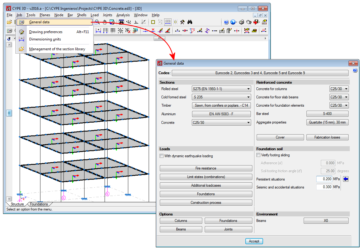
Two new options have been implemented in the Job menu: “General data” and “Dimensioning units”. Details of the “General data” dialogue box are provided in this section.
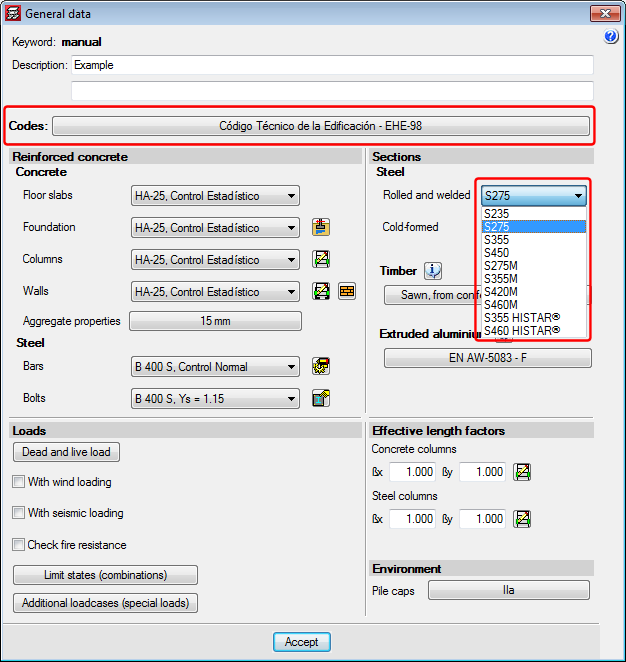
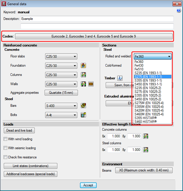
The “General data” option provides users with a central management dialogue box of all the options affecting the design and check parameters of the program (for both Structure and Foundations tabs).
Added to the existing options, which were previously located in other menus, are the following options:
- In the reinforced concrete section
- Cover
By clicking on this option, users can edit the cover of the reinforcement bars of beams and columns. - Aggregate properties
The nature and maximum size of the aggregates for columns, floor slab beams and foundation beams can be defined here. - Steel fabrication loss
Allows users to define the steel fabrication loss of columns and beams, as well as the fabrication loss for foundation elements.
- Cover
- Loads section
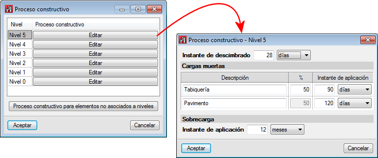
- Construction process
By using this option, users can edit the construction process for deflection checks of reinforced concrete beams. The editing process is carried out per level, and so only the beams located in each level are affected. The construction process of beams not located on a level can be defined by selecting the “Construction process for elements not associated to levels” button.
The editing process consists in defining the instant when the beam is unpropped, the instant when the dead loads are applied and the instant when the live loads are applied.
- Construction process
- Options section
- Columns
Options regarding the design and check of columns are found in this section. Reinforcement tables can be configured, as well as design and check options, reinforcement arrangement options and stiffness coefficients. - Beams
Options regarding the design and check of beams are included in this section:- Reinforcement and layout tables
- Error valuation
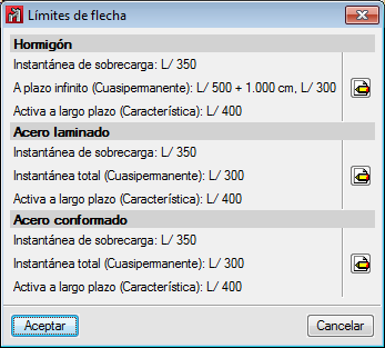
- Deflection limits
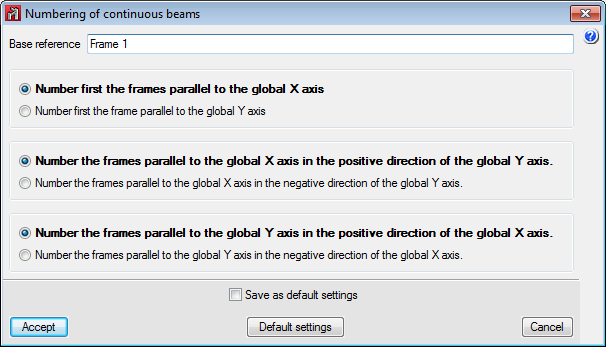
Users can configure the deflection limits depending on their material (concrete beams, rolled steel beams and cold-formed steel beams). - Numbering of continuous beams
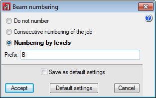
The program numbers frames based on a base reference provided by users and the established configuration. - Numbering of beams
The program offers users the option whether or not to number beams. Beams are numbered based on a base reference provided by users and the established configuration.
- Columns
- Environment section
The exposure class and specific exposure class for beams are defined here. The configuration defined in this section affects all beams, although users can, however, configure a specific environment for each beam in the Bar menu.
Job menu. Dimensioning units
Allows users to establish the units in which the element dimensions are displayed in drawings.
New job assistant
The new job assistant present in previous versions has been substituted by the General data dialogue box, as it in this box where all the parameters affecting the analysis and design parameters of the program are located.
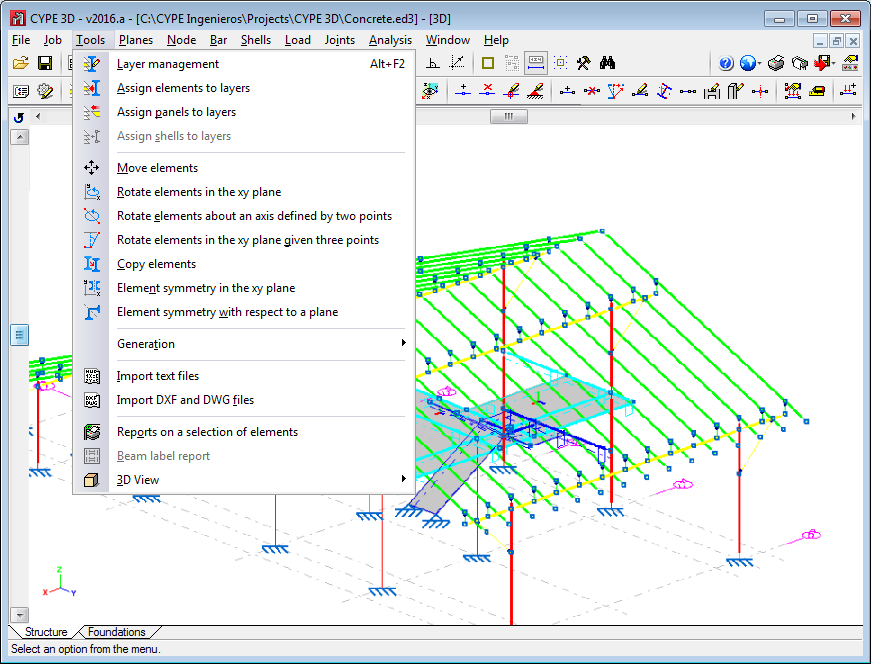
Tools menu (new)
Options related with layer management, generating, geometry management, 3D views and specific operations carried out on elements (which in previous versions were located in the “Job” menu), have been incorporated in this menu to improve the options structure of the program.
The option to print beam labels has also been implemented.
Planes menu
Two new options: Levels and Grids, have been incorporated in the “Planes” menu. These options are essential when introducing, revising and viewing jobs with “Column” and “Beam” type structural elements.
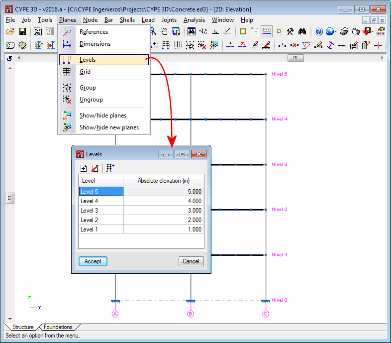
- Levels
Levels are horizontal planes parallel to the XY global plane, situated at a given global elevation where users can introduce a spatial sub-division as is the case in structural buildings. Assignment of the elements to the different levels is automatic. Elements situated between two levels are assigned to the closest lower level.
Levels are defined to support the introduction of structural elements as well as to define views of a level (which help when working on the elements of the structure). If columns are introduced, levels must be defined. Columns must begin and end at two different levels (although they may do so with there being an elevation change with respect to the two levels).
With this option, users can edit or delete levels. If the elevation of a level is modified, any elements contained in that level will be automatically displaced to the new position.
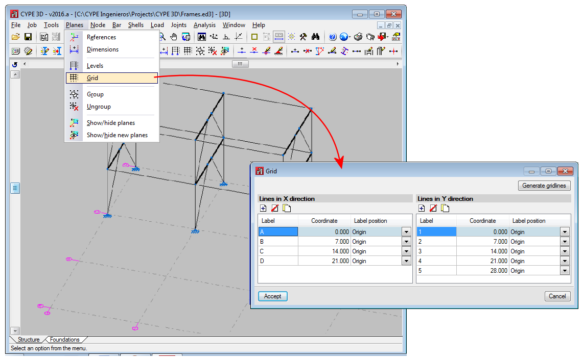
- Grids
A grid is a mesh composed of lines parallel to the global x and y axes. These lines define a spatial division of the structure in its elevation. Users can assign a name to each gridline and control the position of the name. Gridlines are defined as support for the introduction of structural elements as well as for when defining elevation views (which help when working on the elements of the structure).
This option allows users to introduce, delete or edit Gridlines. A rectangular grid generator has been implemented. If the position of a gridline is modified, all the elements contained on the line will be automatically displaced to the new position.
By default, the grid will always be visible on-screen, unless it is deactivated using the option: “Planes > References”. The grid can also be displayed on drawings.
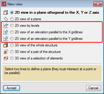
Window menu. Plan views and elevation views
If levels and grids have been defined, the program will allow users to create views for levels and elevations. Once the views have been defined, it is possible to move from one level to the next, or from one elevation to the next, using the 

 buttons (up, down, and select levels or elevations) of the scroll bar on the left of the main screen.
Both level views and elevation views are 2D views. Therefore, any element introduced in a view will be contained in that plane. In the case of level views, the program displays elements belonging to the level and those reaching or beginning from it. The program allows for the views to be rotated, so users can better adjust their view of the elements.
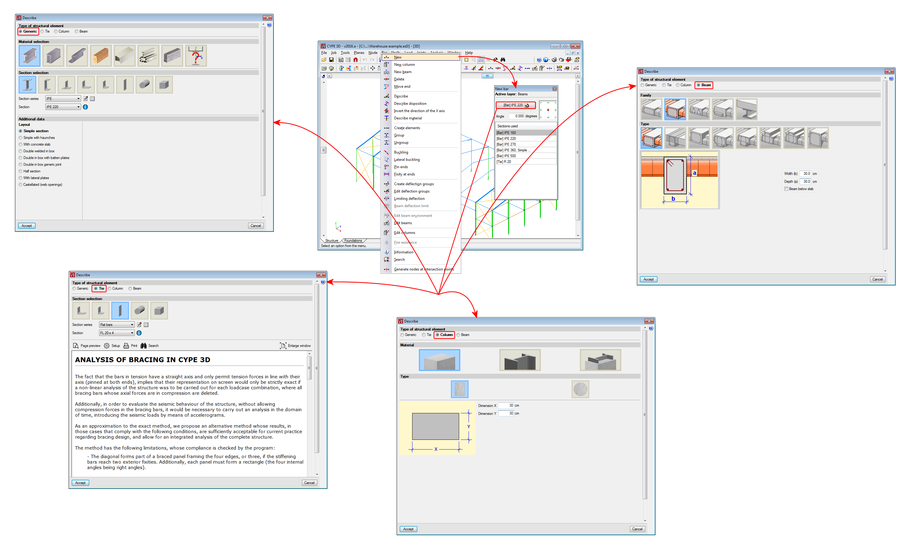
Bar menu. Introduction of bars as structural elements
As of the 2016.a version, users are required to define in CYPE 3D the structural function an element carries out. There are 4 different structural types available:
- Generic
The element does not have a structural role known by the program. It will be designed, edited and checked as were elements in previous program versions. - Tie
The element forms part of a bracing system and only works in tension. This type was already available in previous versions. - Column
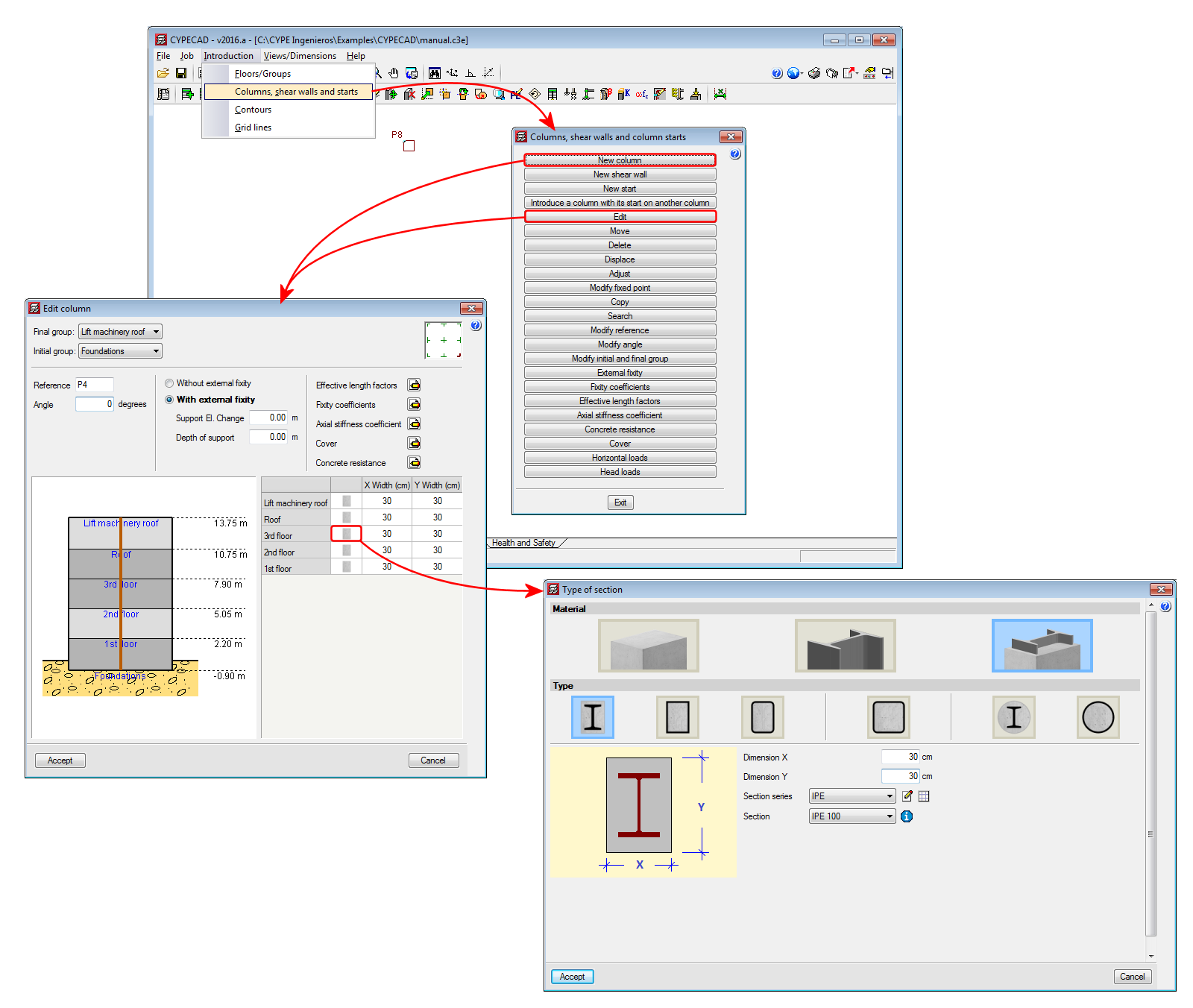
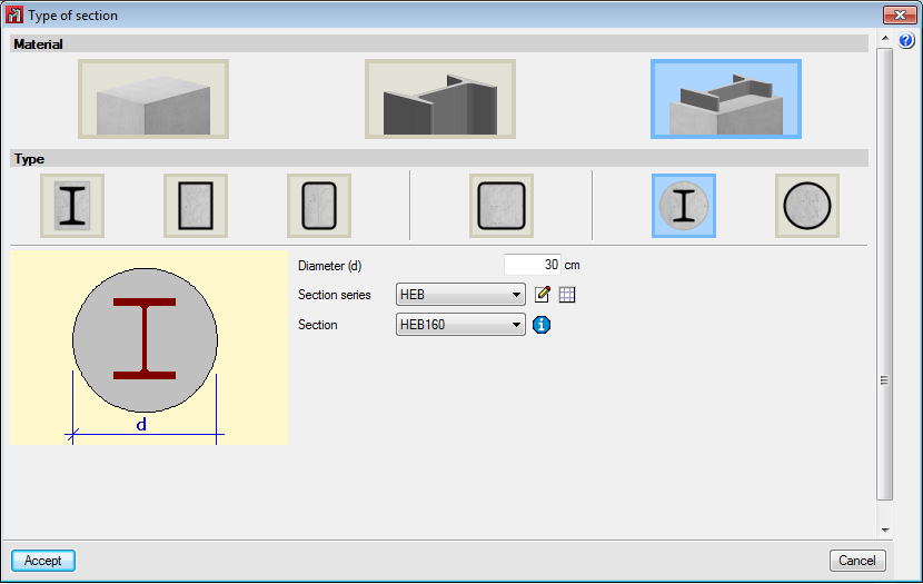
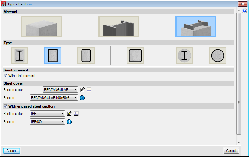
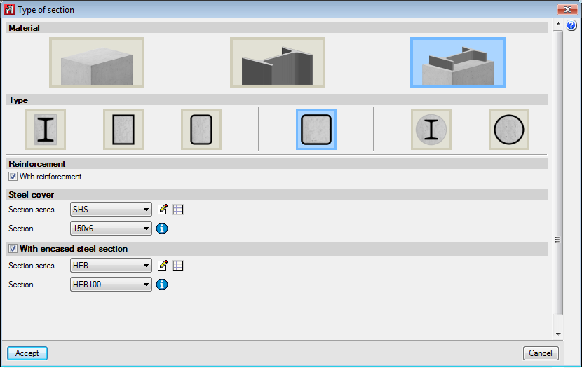
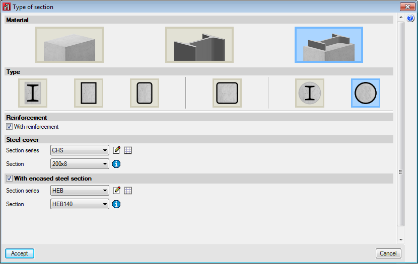
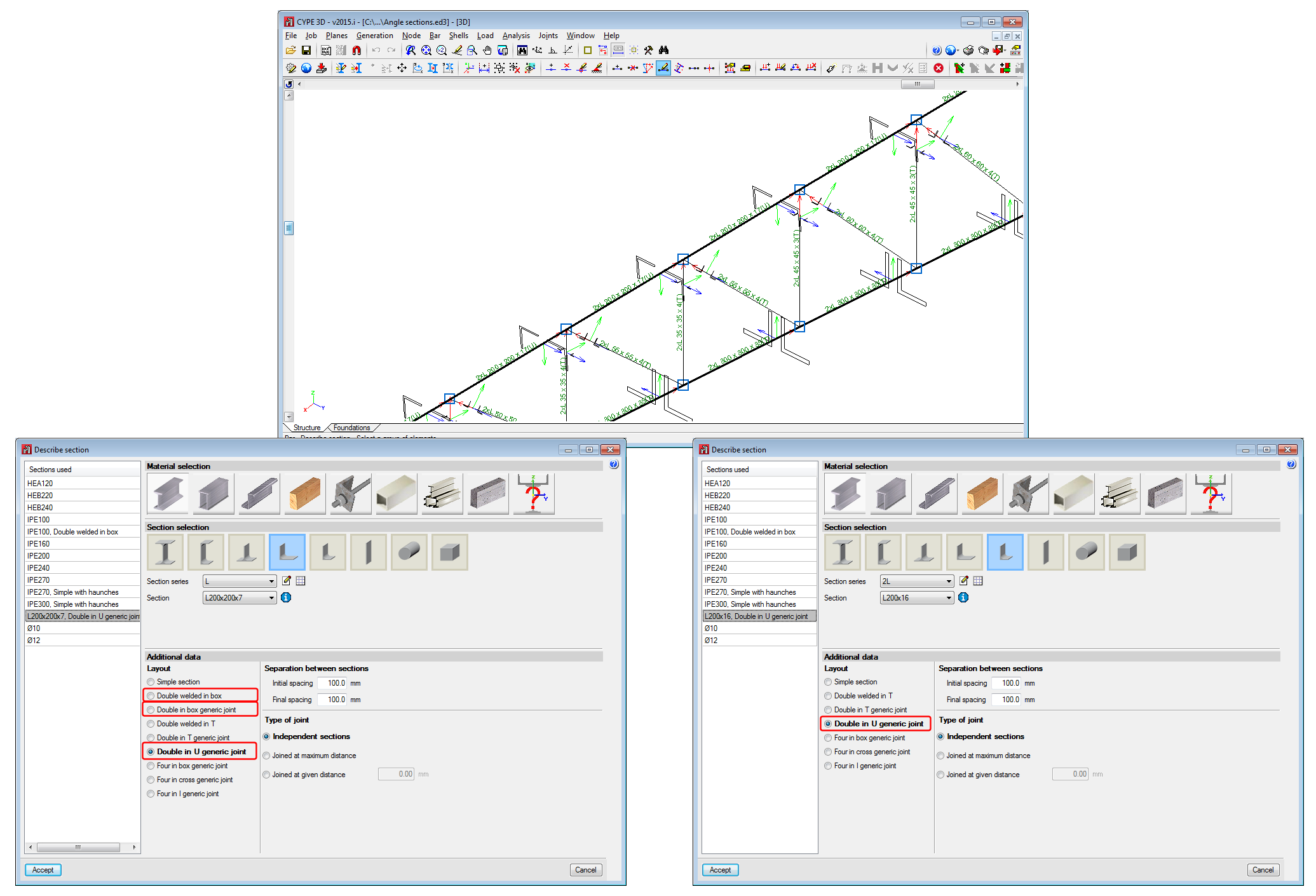
The element is a column. It is designed, edited and checked using the Advanced column editor, and hence, it can only be designed in accordance with the codes that are available with the editor. Design codes which are no longer in force or in use are not usually available with the editor. The sections that can be assigned are:- Rectangular or square reinforced concrete sections
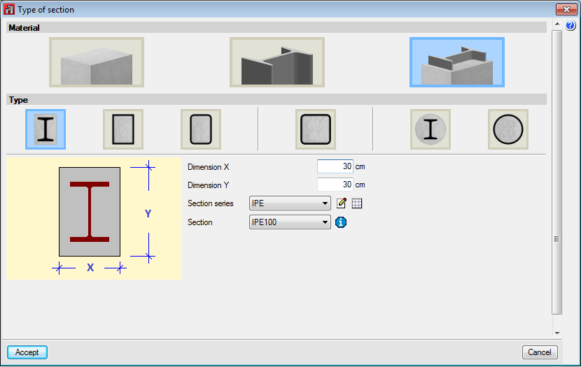
More information on this module, used by both CYPE 3D and CYPECAD and used to design these structural elements, can be found on the Concrete columns webpage.Steel sections
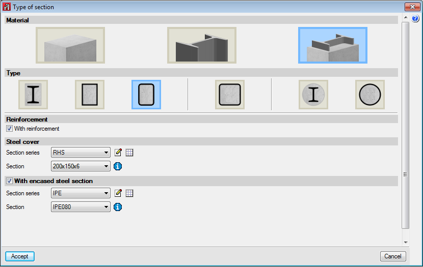
Can be rolled steel, cold-formed steel or welded steel.Composite steel and concrete sections
More information on this module, used by both CYPE 3D and CYPECAD and used to design these structural elements, can be found on the Composite steel and concrete columns webpage.
- Rectangular or square reinforced concrete sections
- Beam
The element is a beam. It is designed, edited and checked using the Advanced beam editor, and so it can only be designed in accordance with the design codes in the editor. The sections that can be assigned are:- Rectangular, L-section, T-section..., lattice or prestressed concrete beams
More information on this module, available for use with CYPE 3D and CYPECAD, can be found on the Concrete beams webpage.Steel sections
Can be rolled steel, cold-formed steel or welded steel.
More information on these structural elements can be found in the section on Properties of Beam-type structural elements of this webpage. - Rectangular, L-section, T-section..., lattice or prestressed concrete beams
Properties of Column-type structural elements
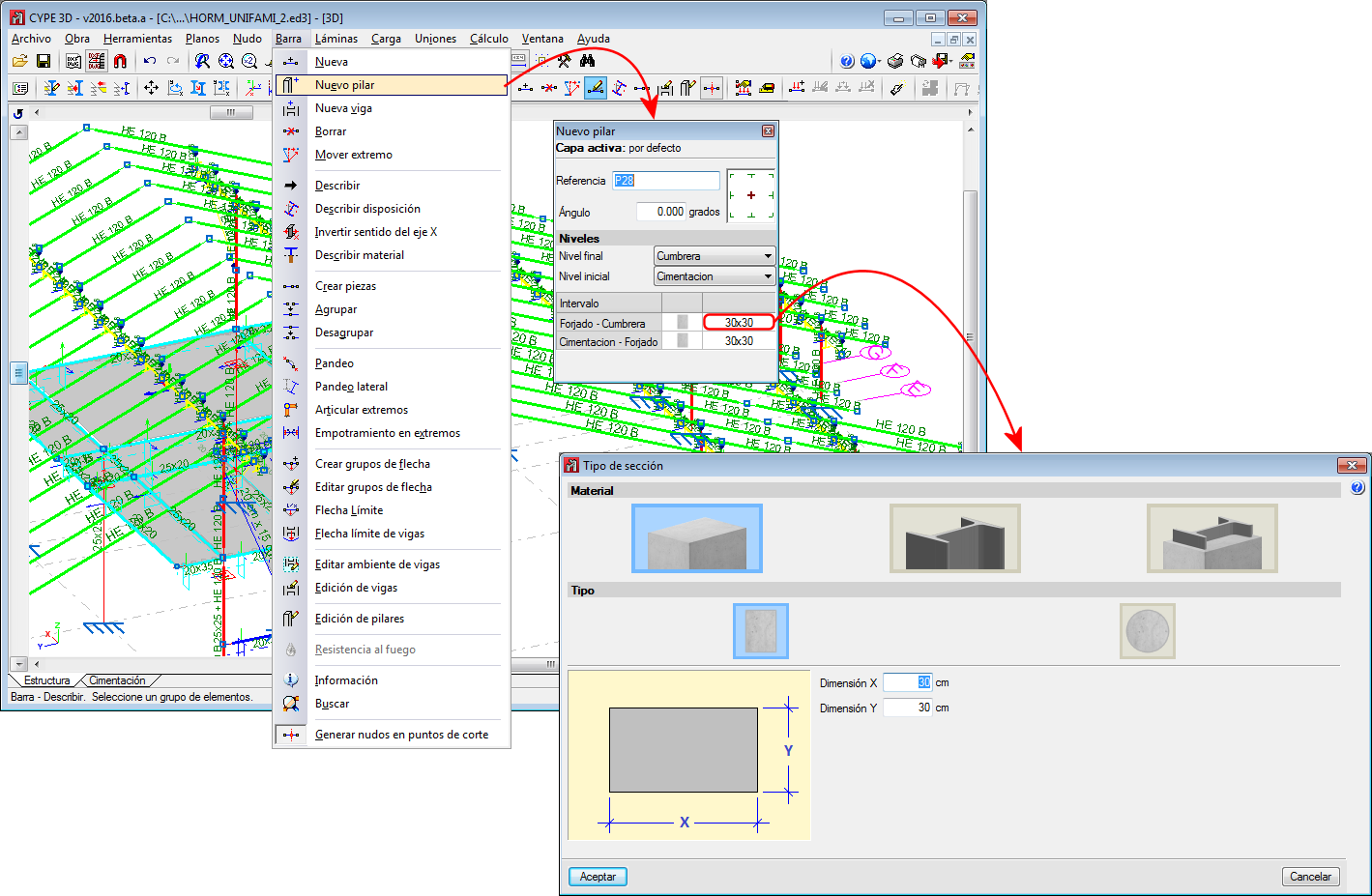
Columns are composed of elements whose structural type has been defined as being a column. A column can be composed of one or more elements. The column elements making up the column are vertical and have the same level parameters. Columns can be created in 3 ways:
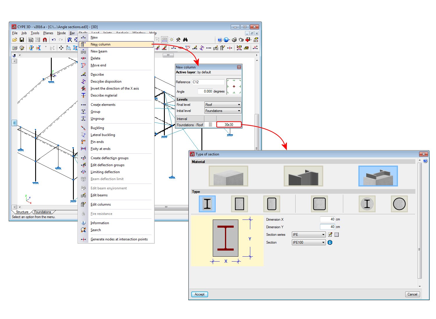
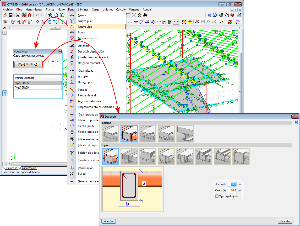
- By introducing a bar using the “New bar” option and selecting a column-type structural element description (Bar > New – see previous image).
- By assigning a column-type structural element to a previously introduced element (Bar > Describe).
- Using the “New column” option of the Bar menu.
Regardless of how they are created, the program will manage the composition/decomposition of the previously introduced columns. It is recommended columns be created using option 3. The “New column option” allows users to create a column between a range of indicated levels with the reference and sections defined by users by clicking with the mouse button at the position where the column is to be introduced.
The element must be vertical and be defined as being between two different levels. The element must be divided into bars, however, in the case of concrete columns, the reinforcement will be continuous along its complete length.
Once a group of elements has been defined as being a single column, CYPE 3D ensures the level parameters are the same for all of them. The level parameters of the column are defined using the “Describe disposition” option in the “Bar” menu.
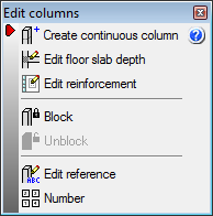
The remaining specific editing option for columns are located in the “Edit columns” option in the “Bar” menu. This option displays a toolbar containing the possible edit options. These options are:
- Create continuous column
Creates a single column from a group of aligned elements - Edit floor slab depth
Allows users to edit the depth of the floor slab at a column node if they wish to assign a different value to that assigned automatically. The depth of the floor slab determines the free height of the column between levels. - Edit reinforcement
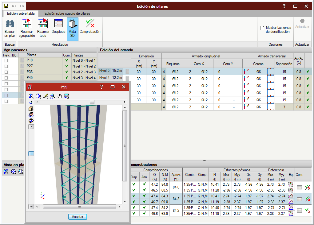
Allows users to edit column reinforcement by opening the column schedule. - Block
Blocks the reinforcement of a column so it is not modified during the design process. - Unblock
Unblocks any blocked reinforcement. - Edit reference
Edits the column references. - Number
Allows users to number consecutively all the columns of the job as of an initial reference.
The program generates a solid model of the column taking into account floor slab depths at the nodes of the elements it is composed of. CYPE 3D automatically analyses these floor slab depths based on the elements reaching the nodes to established the real size of the column as well as the free height of the spans it is composed of.
Properties of Beam-type structural elements
A beam is an element which has been assigned as being a beam-type structural element. A beam cannot be vertical, and the angle between its XZ plane and the vertical plane containing it must be zero (i.e. it must not rotate about the longitudinal axis of the beam). Beams can be grouped and so form continuous beams (beam alignments), with the following conditions:
- The end node of one is the starting node of the next.
- All are of the same type of material (concrete, rolled steel or cold-formed steel).
- If all are made of concrete, they must be of the same type of concrete.
Beams (and continuous beams) can be created in 3 ways:
- By introducing a bar using the “New bar” option then applying a beam-type structural element.
- By assigning beam-type structural element to a previously introduced element.
- Using the “New beam” option in the Bar menu.
In all these cases, the program will manage the composition/decomposition of beams that were introduced previously. The recommended option is option 3. The “New beam” option allows users to easily create a continuous beam by introducing the bars it consists of. To finish off the introduction, click on the right mouse button and at that moment, CYPE 3D will create a continuous beam with all the elements that have been introduced, if possible.
The element cannot be vertical, it does not have to belong to a level, however when they have been defined, they will be assigned to the closest level below the beam. The element can be divided into bars, but if it is a concrete beam, the reinforcement will be continuous along its complete length.
If the continuous beam is composed of more than one element, the deflection groups of the elements must be completely contained within the continuous beam. CYPE 3D will carry out the deflection analysis indicated by the design code for the beams of the continuous beam. No additional deflection limits have to be defined using the “Limiting deflection” option, even though in this case, the program will additionally carry out the check.
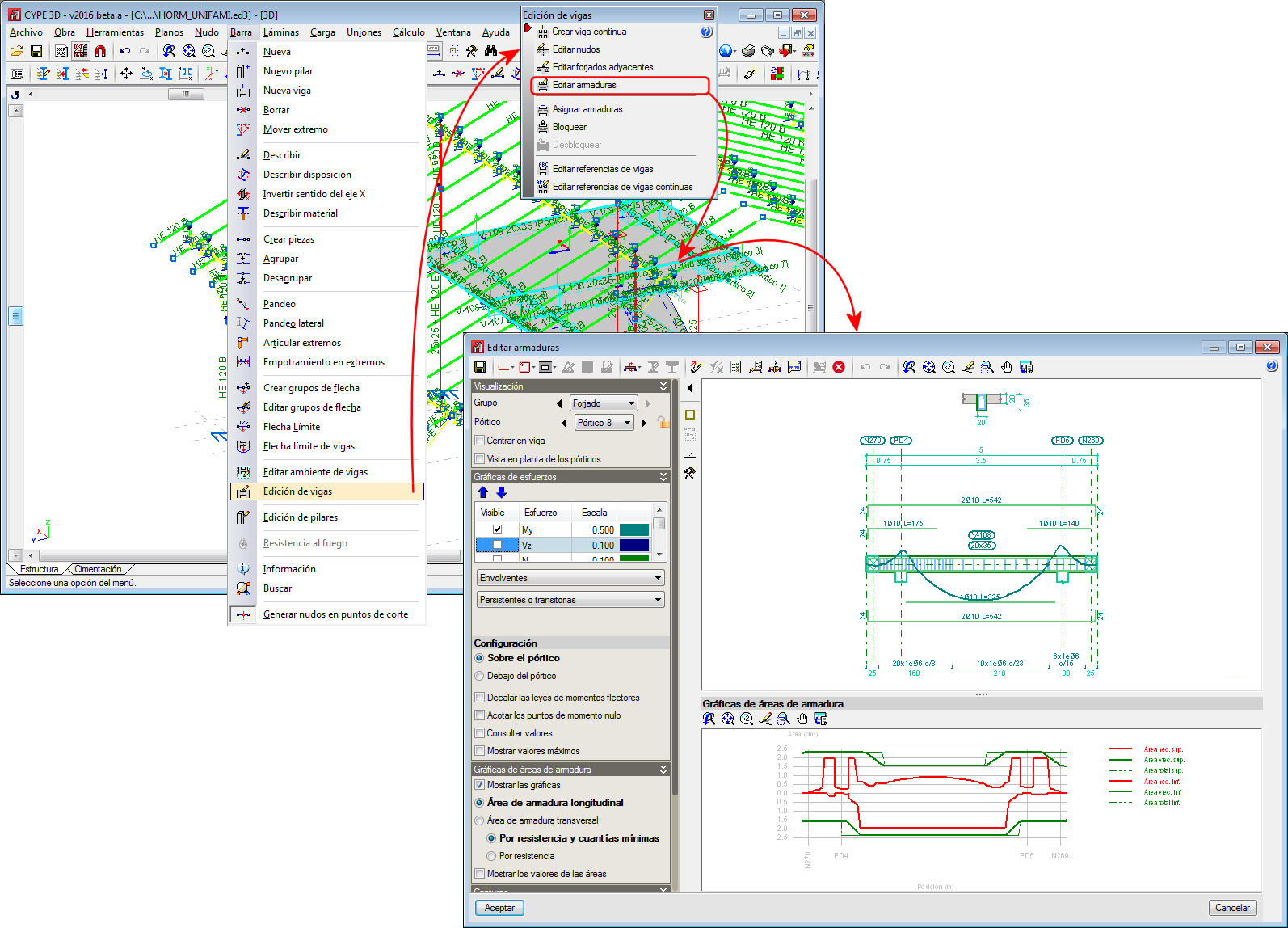
The remaining specific options for editing beams are found in the “Edit beams” option of the “Bar” menu. This option displays a toolbar containing options to edit beams. These are:
- Create continuous beam
Creates a new continuous beam by selecting the beams which wil become part of the new continuous beam. - Edit nodes
Edits the geometry of a continuous beam node if it is to be different to that which was established automatically. The geometry of the node affects the free span of the beams which is represented in the beam reinforcement editor, and therefore, the length of the reinforcement that is provided. - Edit adjacent floor slabs
Allows users to describe the floor slabs next to the bars making up the beams. With this option, the depth of flat beams can be defined and whether or not floor slabs are to be shown in the beam details drawing. Floor slabs are taken into account when checking the fire resistance of steel beams. - Edit reinforcement
Edits the beam reinforcement and opens the Advanced beam editor. - Assign reinforcement
Allows users to copy reinforcement from one beam to another. - Block reinforcement
Blocks the reinforcement of a beam to avoid if from being modified during the design process. - Unblock
Unblocks blocked reinforcement. - Edit beam or continuous beam references
Allows users to edit the beam references.
The beam reinforcement editing process implies that a solid model of the beam has been generated bearing in mind the size of the nodes of the elements making it up. CYPE 3D automatically obtains the geometry of these nodes based on the geometry and position of the elements not belonging to the beam. In any case if the analysis were not to be satisfactory, users can define their own node geometry.
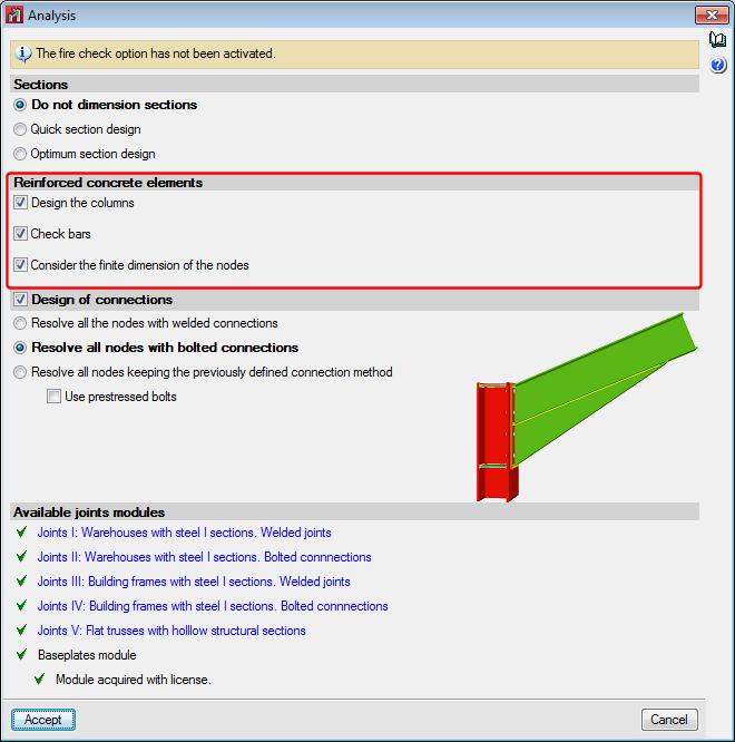
Analysis menu
In the “Analysis” dialogue box (Analysis > Analyse), users can indicate whether reinforced concrete elements are to be designed. The section options affect steel columns and beams, even though in that case, the design process differs to that applied to bars defined as generic-type structural elements.
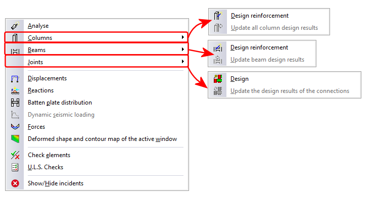
3 new options have been implemented in the “Analysis” menu (Columns, Beams and Joints), which open a series of design and analysis result update options:
- Design
Redesigns elements that have not been blocked. - Update design results
Once the elements have been edited, the results from the previous check may not be up to date (the program emits a warning if this is the case). Using this option, the results can be updated so the information displayed on-screen corresponds with the current definition status of the element.
The options corresponding to connections already existed in previous versions, but have been moved to this menu due to a better coherence of the options.
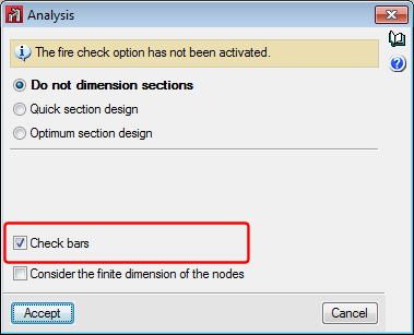
The “Check elements” and “U.L.S.” checks also include changes.
- Check elements
This option substitutes the old “Check bars” option. Now, users can use this option to check bars bearing in mind their structural-type.
For beams and columns, the corresponding editor is displayed to carry out the required changes. For any other type, a dialogue box appears displaying a list of all the sections of the series corresponding to the selected bar, indicating which sections meet all the checks and which do not. When the option is closed, if any changes have occurred, the structure will have to be re-analysed. Bars are displayed in different colours depending on whether or not they pass the checks. - ULS checks
Allows users to consult bar checks bearing in mind their structural type. When a bar defined as being a generic or tie-type structural element, the check panel is displayed bearing in mind their structural type. Bars are displayed in different colours depending on whether or not they pass the checks.
Drawing selection
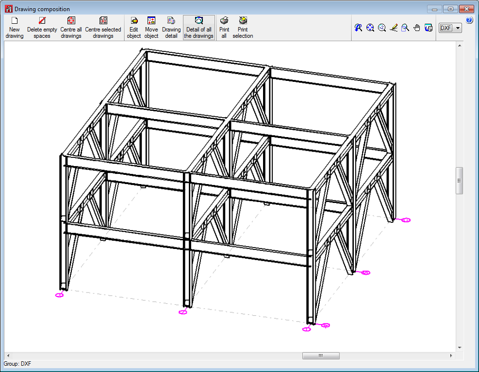
With the new structural elements that have been introduced, CYPE 3D now generates the following drawings (File > Drawings):
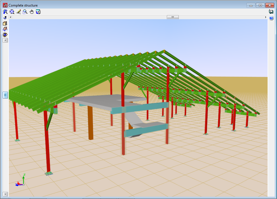
- 3D structures
- Foundation floor plan drawing
- Foundation layout drawing
- 2D plane drawing
Drawing of a 2D view with steel connections. Users can include the references of the connections that have been applied and attach their details. - Joints
- Frames drawing (New)
- Detailing of columns (New)
- Column schedule (New)
User license
For CYPE 3D to design new structural elements (Columns and beams), the user license must include the following modules (as well as the required permits to use CYPE 3D):
- To design reinforced concrete columns
The user license must include the Concrete columns module. - To design composite steel and concrete columns
The user license must include the Composite steel and concrete columns module. - To design reinforced concrete beams
The user license must include the Concrete beams module. - To design steel columns or beams
If the column-type or beam-type structural elements are made of steel (rolled, cold-formed or welded steel), the program does not require any additional module to analyse them.