Update history​​
CYPE 3D
Option for highlighting or not highlighting objects when selecting using a rectangle
- Published on
- 2025.b
Selecting by bar or by rectangle when displaying the forces of a selection of bars
- Published on
- 2025.b
Prestressing stress for bars with only tensile behaviour
- Published on
- 2025.b
Ibarra-Medina-Krawinkler plastic hinge
As of version 2025.b, it is now possible to enter "Ibarra-Medina-Krawinkler" type plastic hinges in CYPE 3D. This hinge allows users to model a behaviour of strength and stiffness reduction after yielding by means of a Backbone type curve.
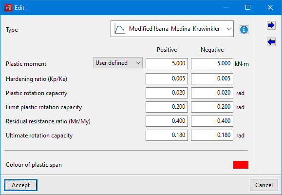
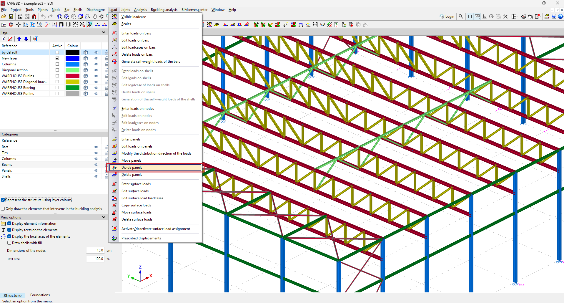
The "Plastic hinges" option in the "Bar" menu defines the plastic hinges' relative position and their properties, as well as the degrees of freedom of rotation on which they act. Up to version 2025.b, "Elastic-linear Hardening" plastic hinges could be defined. From now on, the new "Modified Ibarra-Medina-Krawinkler" type can also be selected.
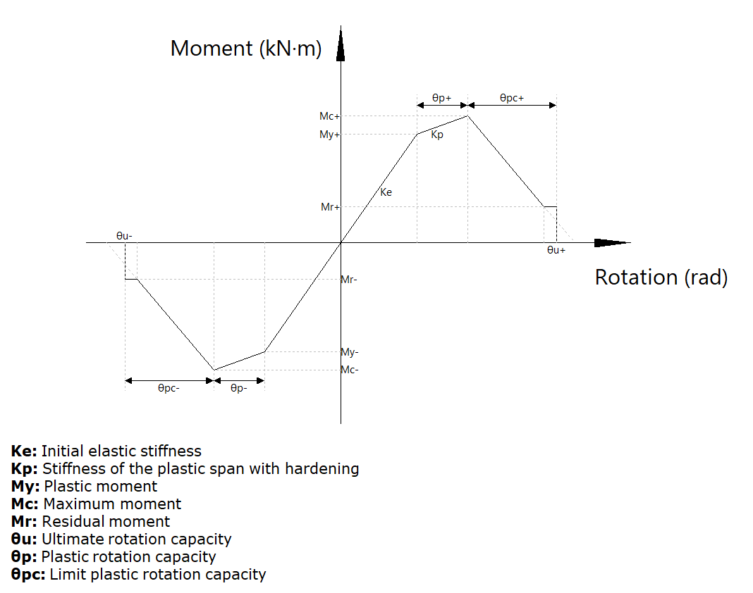
The data required to define the behaviour of a plastic hinge for a given degree of freedom of rotation are shown in the following image.
In the entry panel for the "Ibarra-Medina-Krawinkler" plastic hinge, there is an aid for visualising the behaviour curve and a legend of the symbols used in the curve.
In the stress display, plastic hinges that have reached the yielding point in the selected combination will be highlighted with an increase in size and a colour change.
- Published on
- 2025.b
Drawing ground stresses in shells with subgrade modulus
- Published on
- 2025.b
Fireproof coating report
- Published on
- 2025.b
Automatically deleting the surface charges associated with panels
In previous versions, when deleting a panel in CYPE 3D, the associated surface loads remained in the model, forcing users to delete the surface loads as well.
As of version 2025.b, deleting a panel will automatically delete all associated surface charges.
- Published on
- 2025.b
Automatically moving surface loads associated with panels
In previous versions, when panels were moved, rotated or copied, the associated surface loads remained in the original position, forcing users to carry out these actions on the surface loads as well.
As of CYPE 3D version 2025.b, the surface loads will be automatically adjusted to the panel's new position.
- Published on
- 2025.b
Adjusting surface loads when modifying panel geometry
Until version 2025.b of CYPE 3D, when moving the vertices of a panel with the "Loads > Move panels" tool, the surface loads associated with the panel remained in their original position, forcing the user to move the surface loads as well.
As of version 2025.b, the surface loads will be automatically adjusted to the new position or geometry of the panel.
- Published on
- 2025.b
Tool for dividing panels
In CYPE 3D version 2025.b, the "Divide panels" tool has been implemented. This tool allows a panel to be divided in two by a straight line.
As well as dividing the panel, all surface loads associated with the panel are also divided. To split a panel, select the two points on the panel outline that define the splitting segment.
- Published on
- 2025.b
Using hardware acceleration for model drawing
As of version 2025.b, CYPE 3D will use hardware acceleration for drawing the model. This implementation provides a smoother movement of the model, among other advantages.
- Published on
- 2025.b
Drawing filled force diagrams
- Published on
- 2025.b


