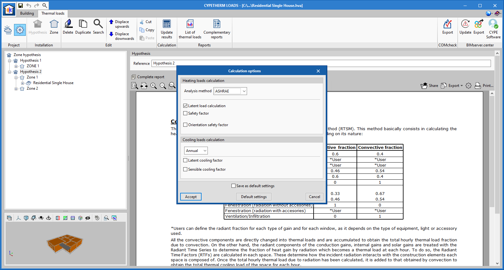
As of version 2022.b of CYPETHERM LOADS, users can activate or deactivate the latent loads calculation from the “Calculation options” menu for calculating thermal heating loads.

As of version 2022.b of CYPETHERM LOADS, users can activate or deactivate the latent loads calculation from the “Calculation options” menu for calculating thermal heating loads.
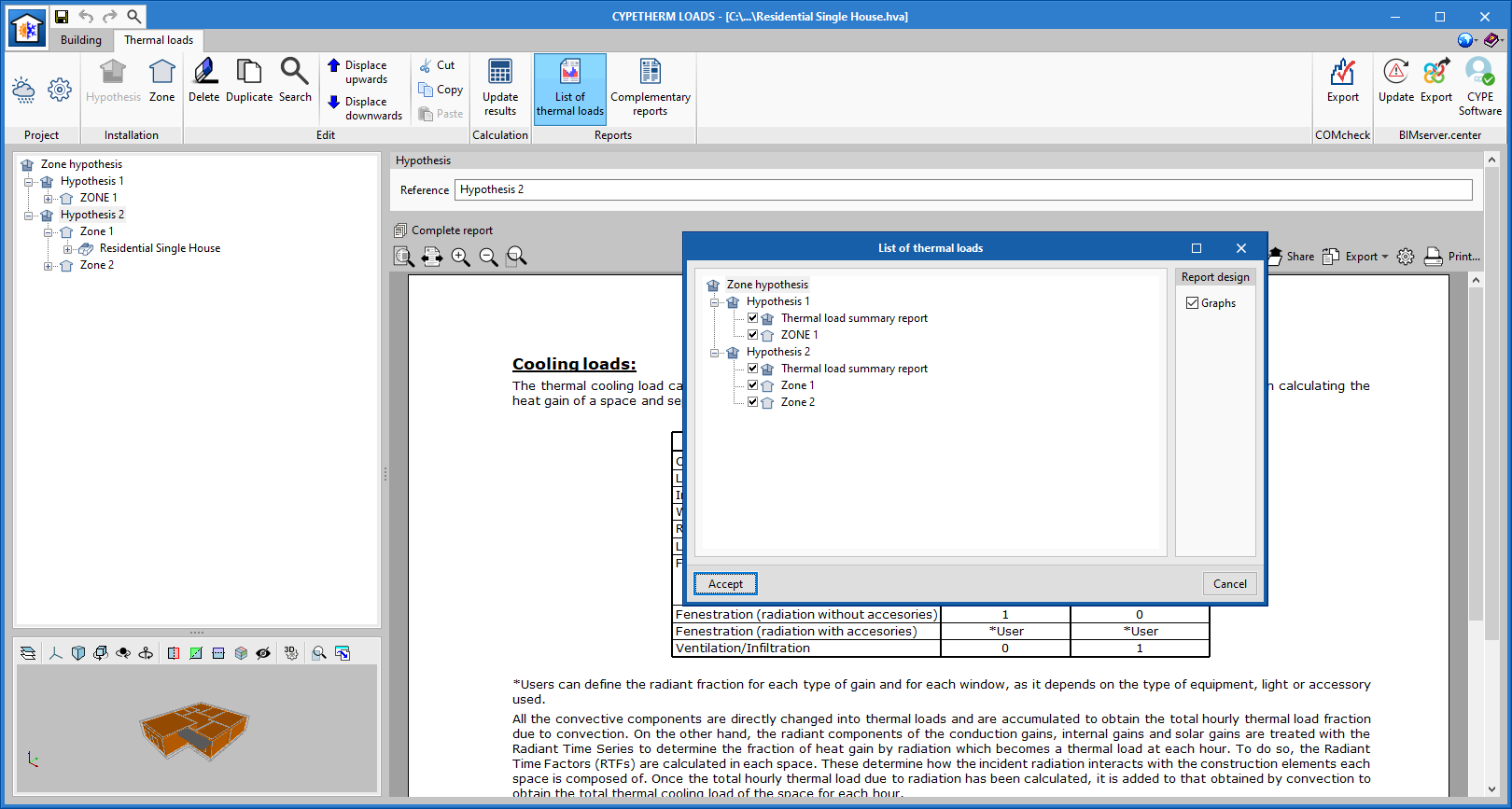
In version 2022.b of CYPETHERM LOADS, new report options have been added in the thermal loads tab, thus providing easier access to the thermal load results report for each loadcase and their areas (graphs can also be included in each one) as well as their additional reports.
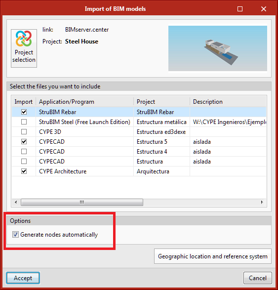
An option has been implemented for automatically generating nodes based on the bars from the selected IFC files.
Up until version 2022.b, the program generated them automatically. As of now, users can decide whether they wish to generate them or not. The program generates nodes from the nearby bar ends.
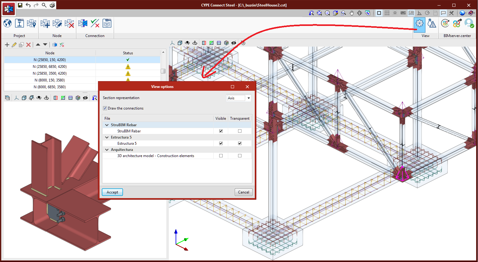
The management for viewing different BIM model files has been added to "View options".
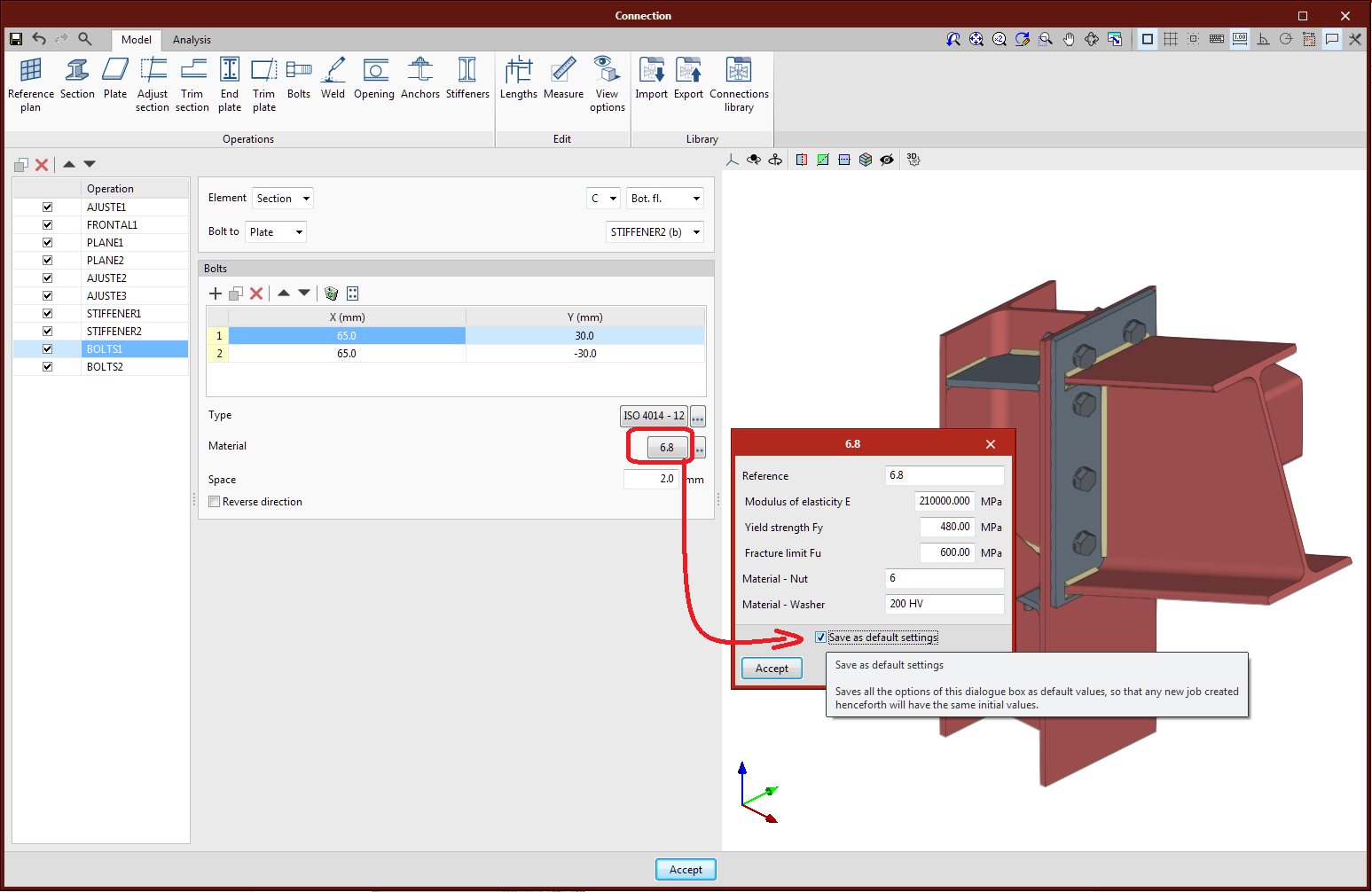
The dialogue boxes for editing the data of plate, bolt and electrode materials include the "Save as default options" option. As soon as they are saved, each new operation will be created with this default data. This option allows users to automatically fill in data that is often common to a connection or a project, with no need to define them each time.
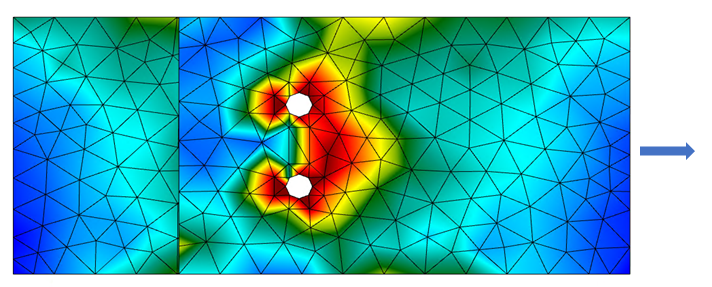
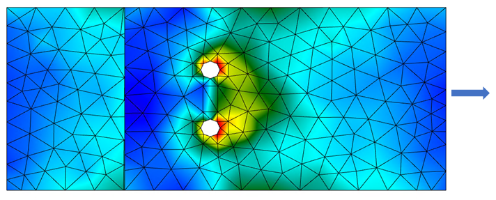
The analysis of bolted connections with prestressed bolts has been added. Up until version 2022.b, the design model for prestressed bolts and ordinary bolts did not change, although the sliding resistance check was carried out for prestressed bolts, in accordance with the selected code.
The prestressed bolts will no longer transmit shear forces through the support of the bolts on the plate and will be transmitted by means of the friction between them along with the transmission through the perimeter of the hole. The simplified model used allows the deformation in the support areas of the connected elements to be minimised.
Assigning the placement of bolts as prestressed or ordinary is data attached to the bolt series, it can additionally be edited directly in the data panel of the bolt series in each operation. In the libraries added by default to the program, there are prestressed bolt series.
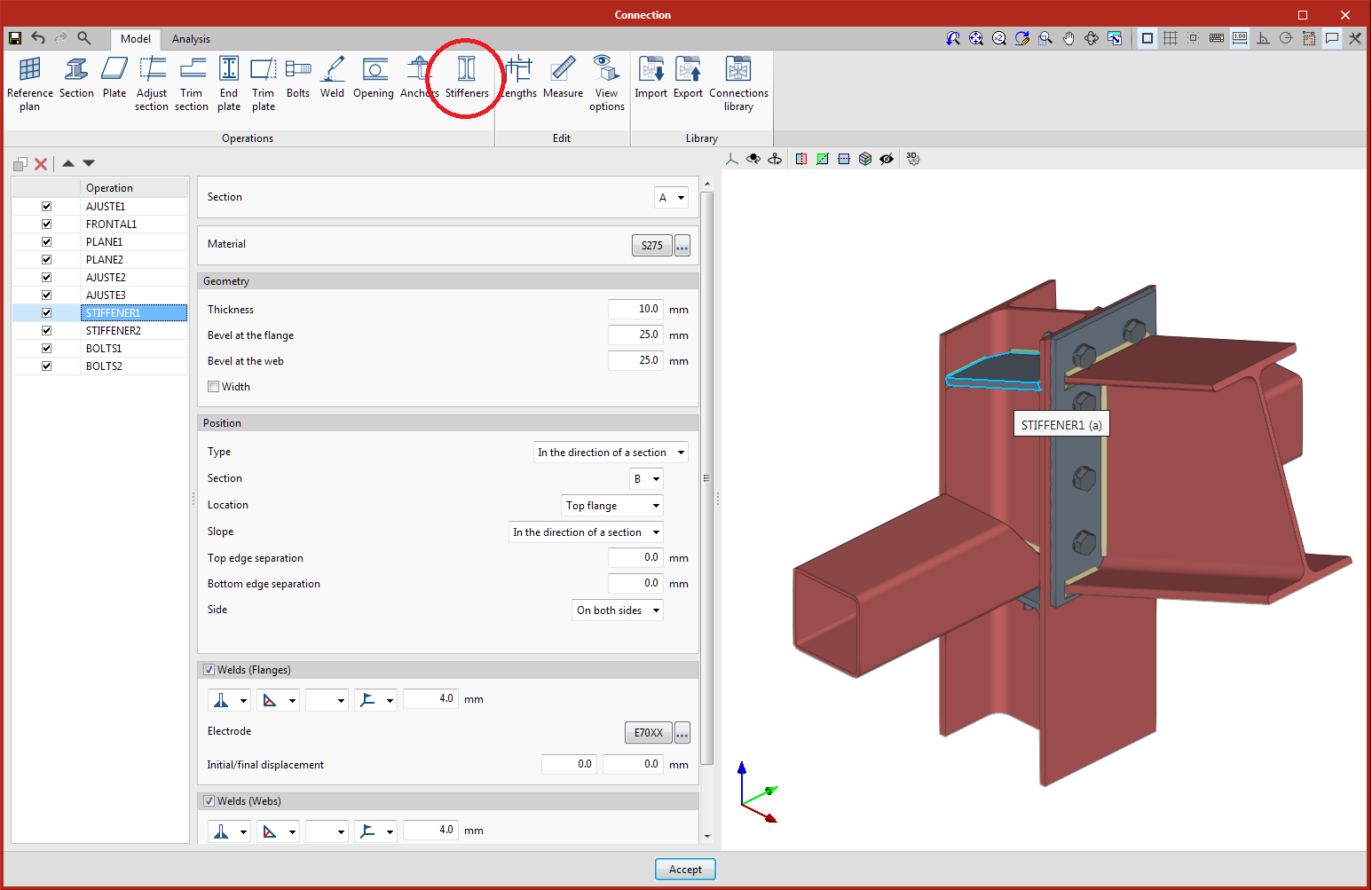
A specific operation has been added for adding stiffeners to I-shaped and U-shaped cross sections. This operation adds the stiffeners and their welds to a section in a position that is relative to the flanges from another section and relative to the section’s local reference system. Options are included for selecting the side, slope, dimensions, etc.
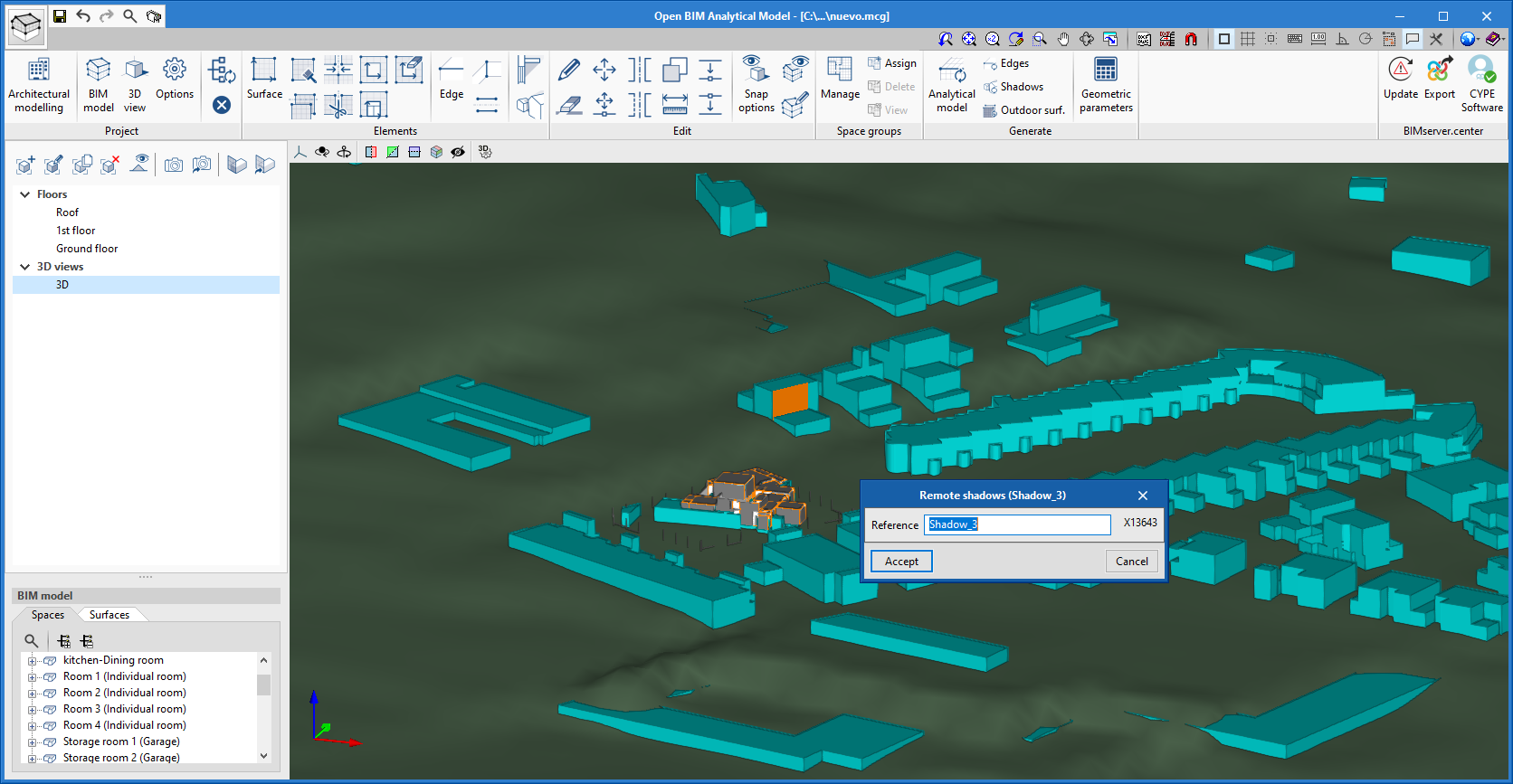
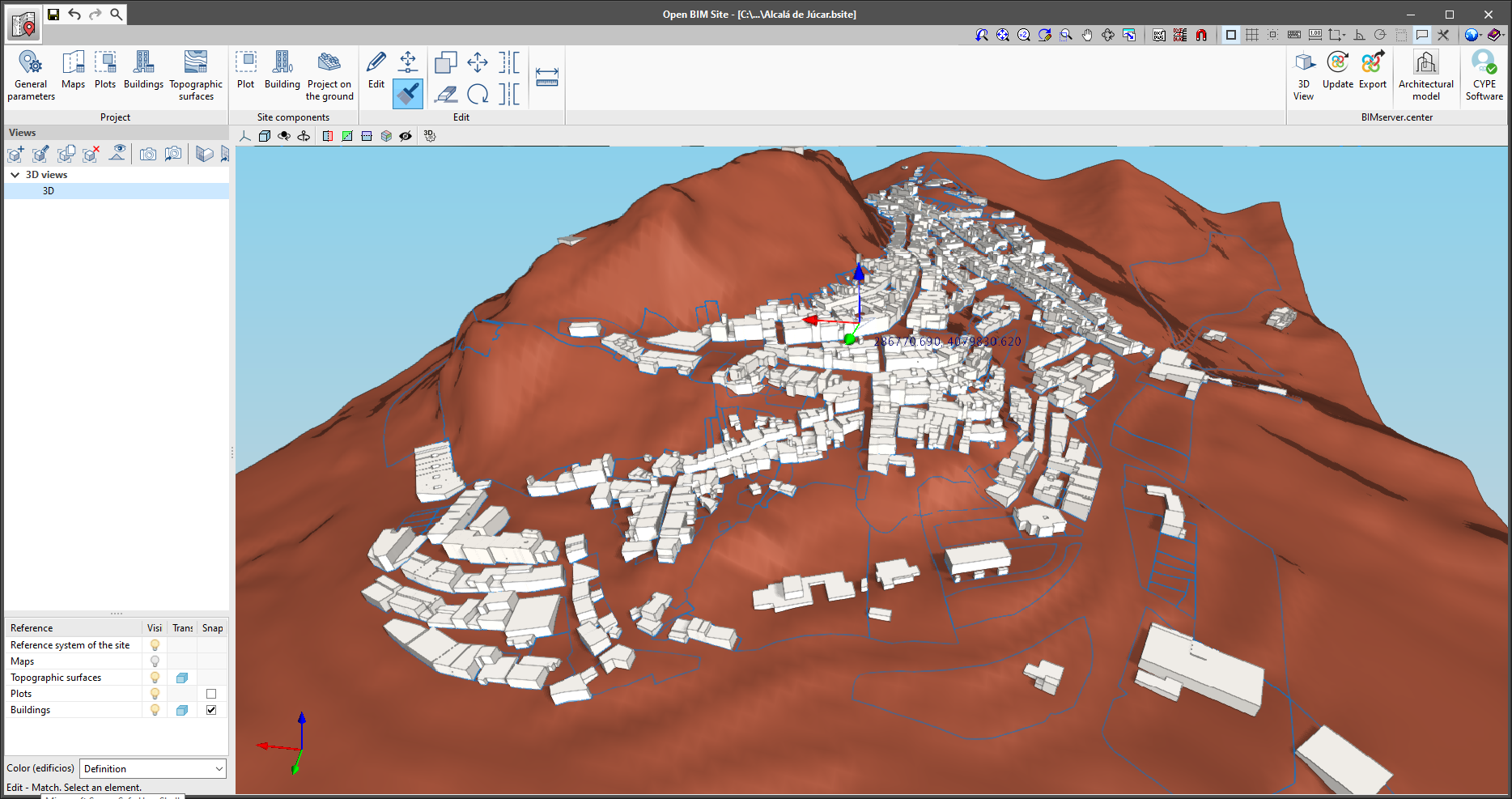
As of version 2022.b, Open BIM Analytical Model can read the buildings entered into the site model that has been defined for the project linked to the BIMserver.center platform. Project location information can be entered via the free Open BIM Site application, available from the BIMserver.center Store.
To read the buildings from the Open BIM Analytical Model environment, the corresponding collaboration must be marked during the linking or updating process of the BIMserver.center project. Once in the application, the buildings will be interpreted as the physical model’s "Own shadows". These elements can be used as a reference to design the analytical model manually or to automatically generate the analytical model. In the latter case, when using the "Analytical model" option in the "Generate" group in the toolbar, shadow surfaces will be created for the analytical model based on the shading elements of the physical model.
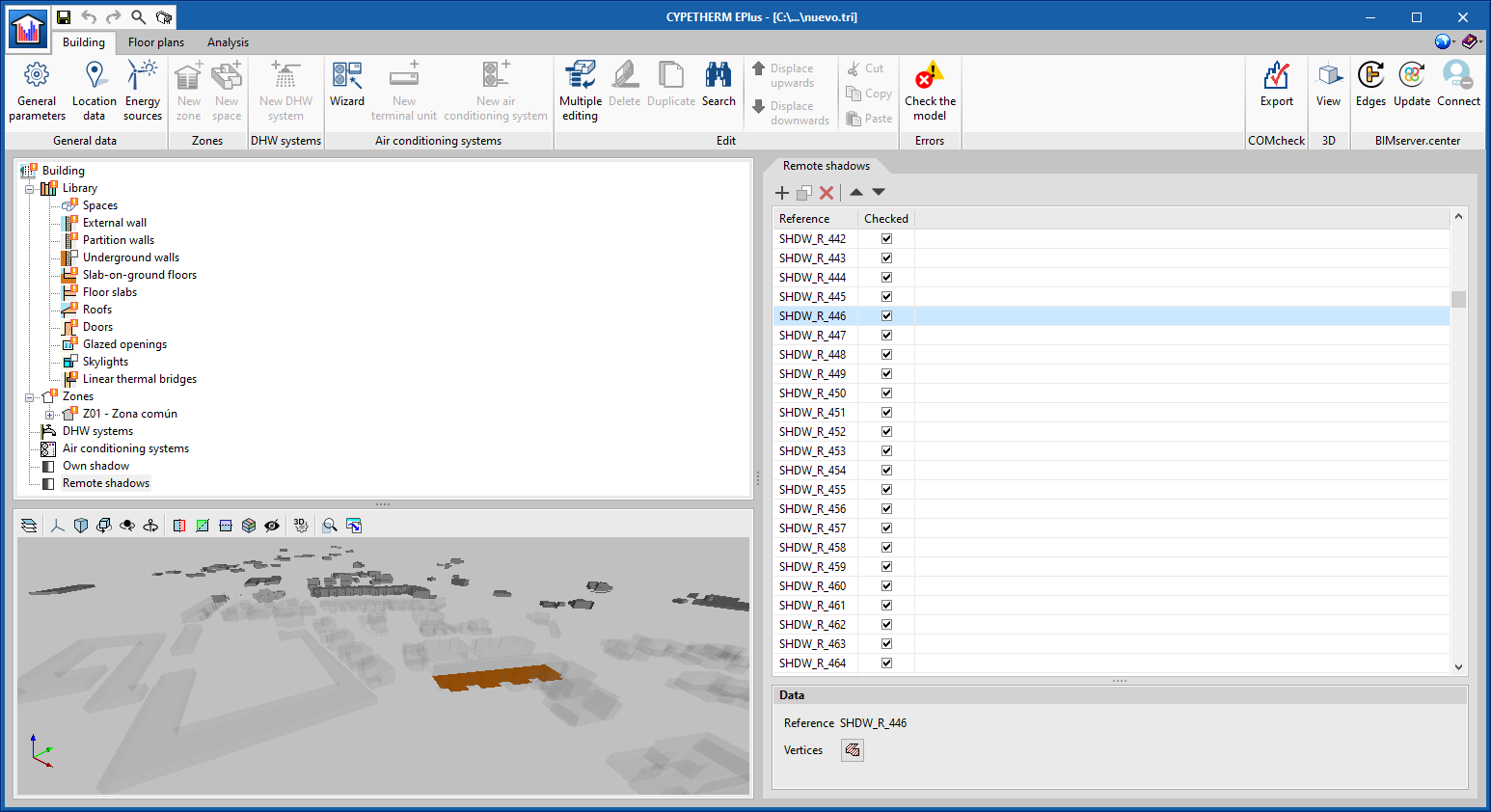
The BIM thermal simulation applications developed by CYPE can use the analytical model from Open BIM Analytical Model and, thus, consider the shading elements generated based on the buildings.
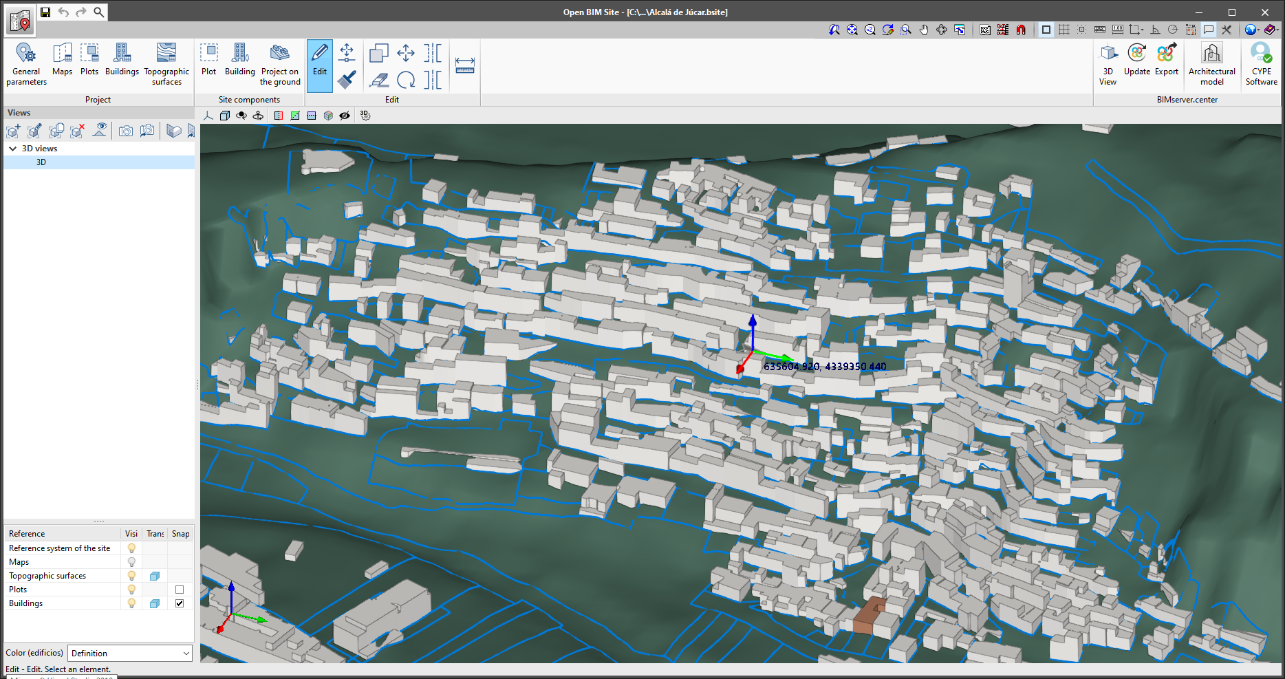
It is now possible to control the visibility of the axes representing the site coordinate origin. This element has been added to the viewing options that appear on the side menu of options on the left-hand side of the drawing area.

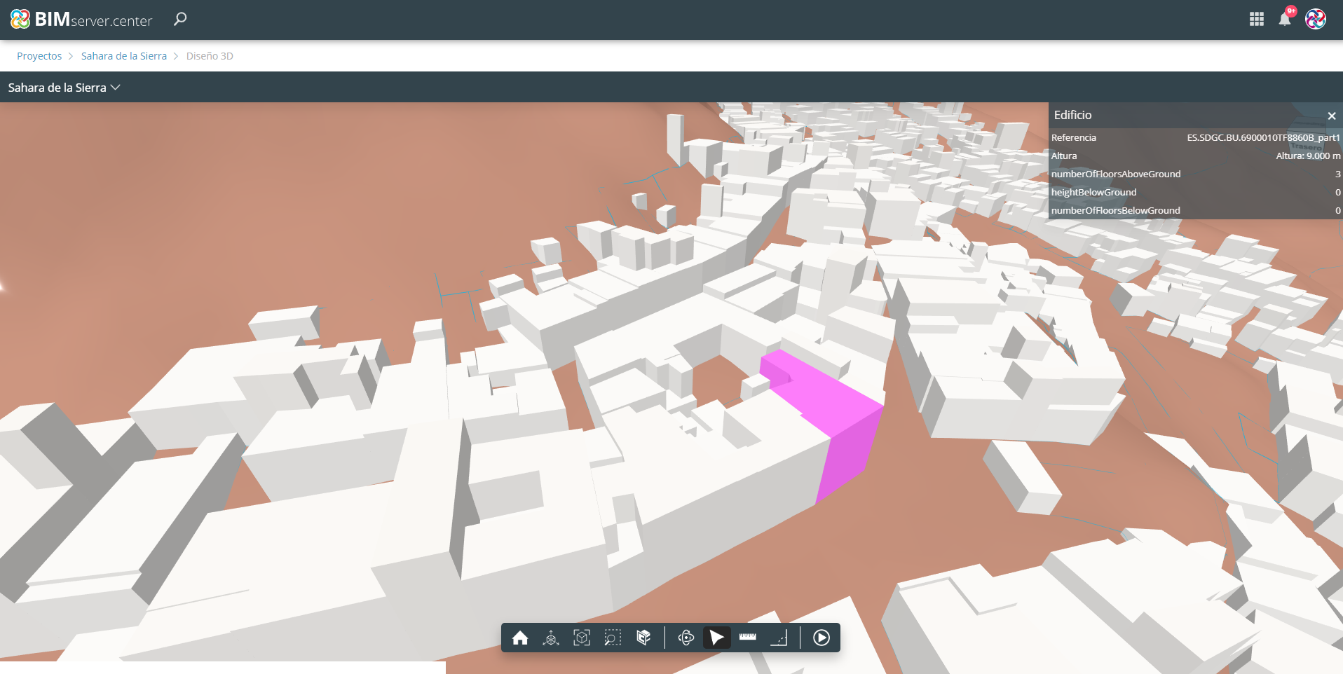
As of version 2022.b, the characteristics of buildings and plots will be exported to the 3D viewing file in gLTF format, used for displaying the model both in the web viewer of the BIMserver.center platform and in the rest of desktop and mobile applications. This way, information can be consulted by the members of the Open BIM project work team.
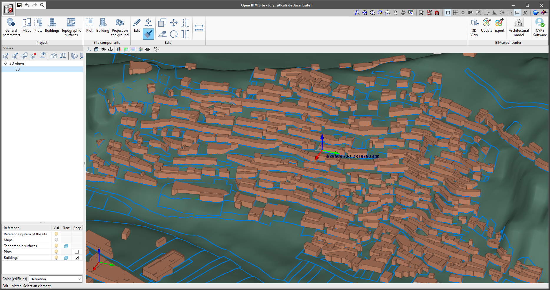
The "Match" tool has been added to the "Edit" group of the application toolbar. With this option, the characteristics of a building can be assigned to others on the same building site. Pressing the button displays a selection panel that allows the user to indicate which of the following data they wish to copy:
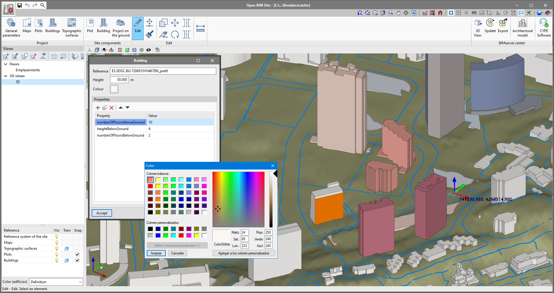
As of version 2022.b, colours can be assigned to buildings in the site model. To do this, the "Colour" parameter has been added to the building configuration panel. Additionally, the "Colour (buildings)" dropdown menu has been added to the side menu on the left-hand side of the drawing space that allows users to control the way in which the colour of the buildings is displayed. This menu contains the following options:
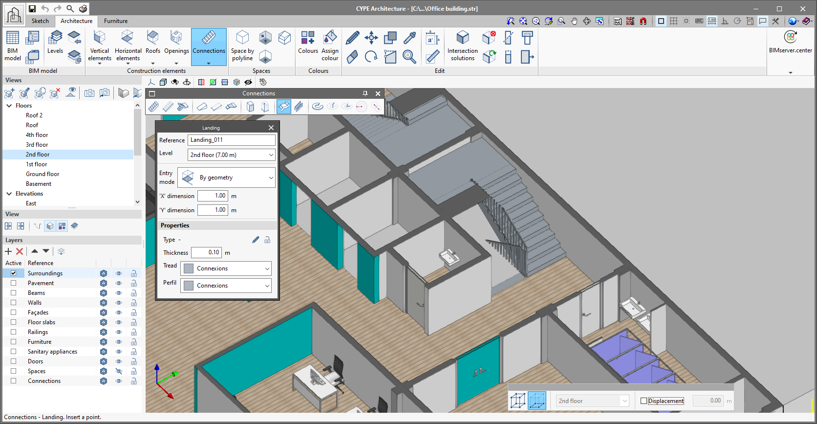
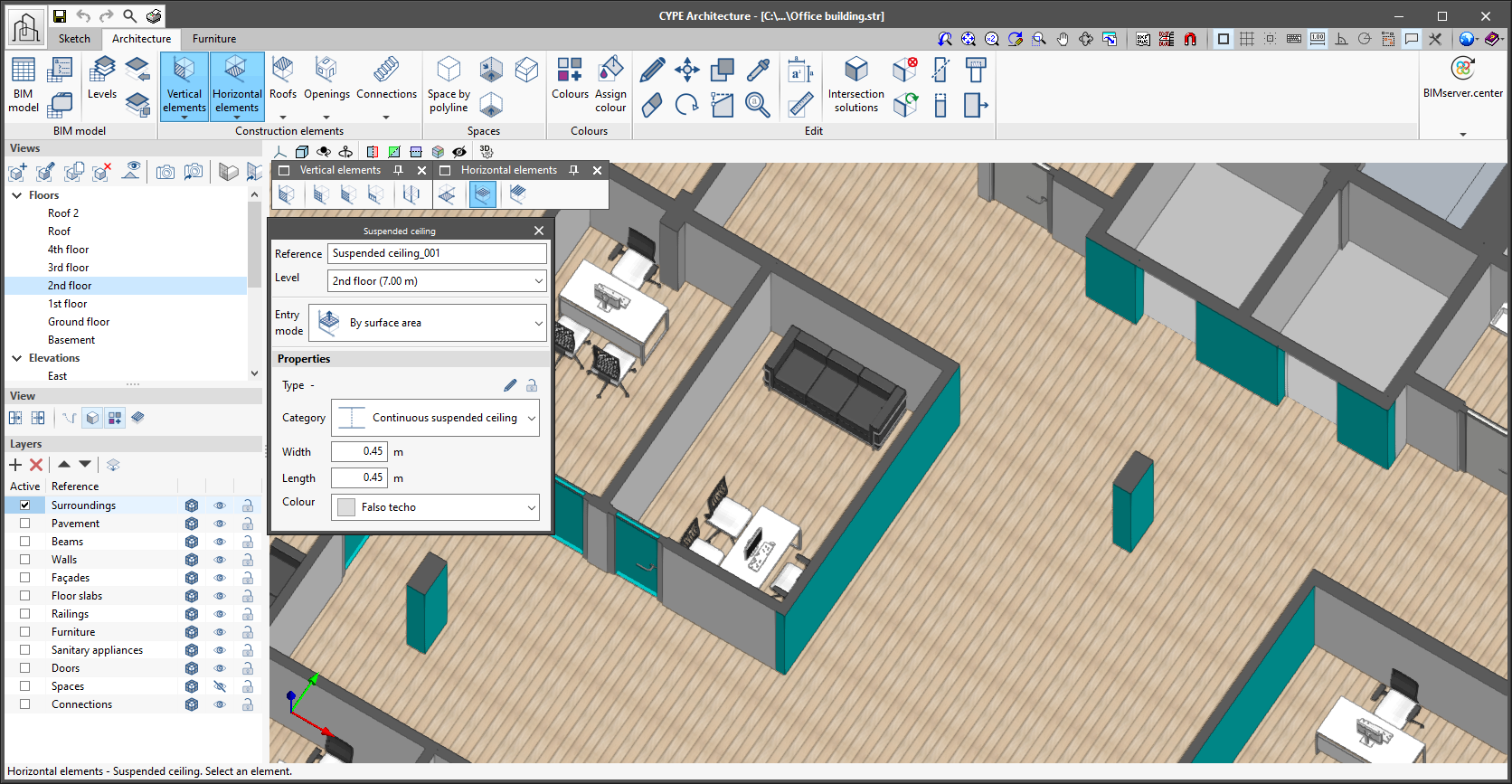
In the "Connections" section, there are two new ways of entering landings for both stairs and ramps: by points and by sketch area.
The following improvements have been made for entering and drawing suspended ceilings.
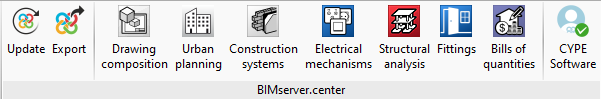
In version 2022.b of CYPE Architecture, new direct links to CYPECAD (structure analysis and design) and Open BIM Carpentry (structure analysis and design of door and window carpentry) have been added. These connections can be viewed from each of the tabs in CYPE Architecture, in the BIMserver.center section in the top menu in the program.
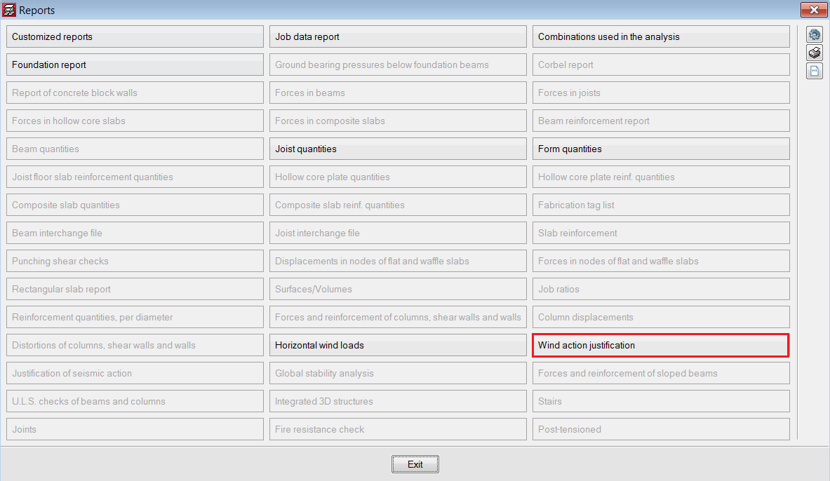
This wind load code was already implemented in previous versions. Now, version 2022.b includes wind action justification.

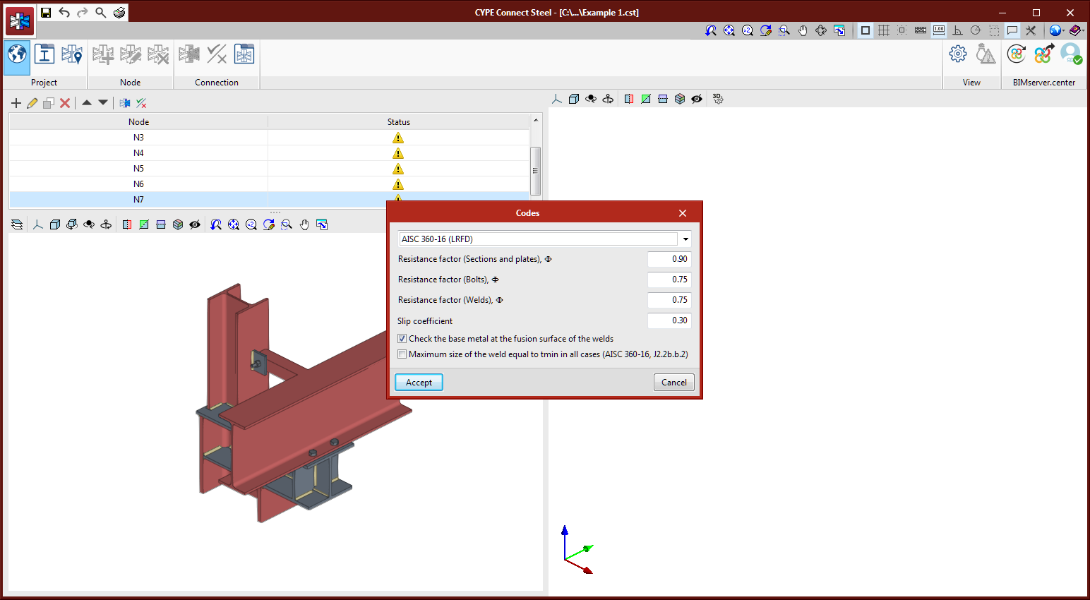
The AISC 360-16 (LRFD code has been implemented for analysing connections in accordance Eurocode 3 and Spanish code EAE.
Specific resistance checks and the layout of prestressed bolts, ordinary bolts and welds have been implemented. For plates, the program will verify that the equivalent Von Mises deformation value does not exceed 5% (EN1993-1-5, Annex C, Section C.8, Note 1).
The detailed checks will show the code’s reference article.
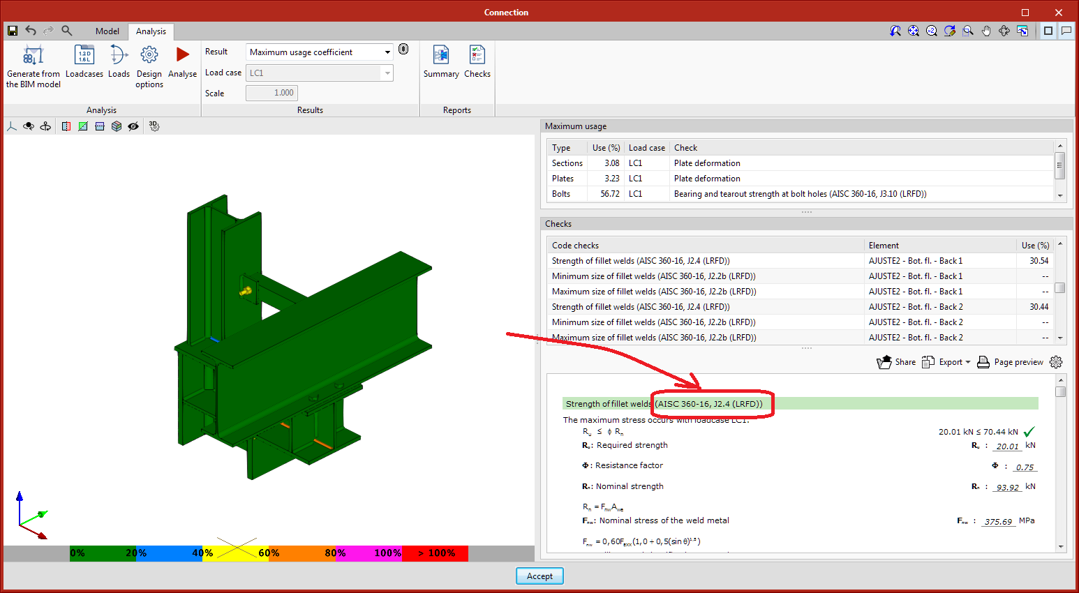
As of version 2022.b, welds will include an electrode material selection. This is carried out because the resistance check for fillet welds compares the required strength of the chord with the filler metal resistance. For codes where the filler metal is assumed to have a higher resistance than the plates to be joined (Eurocode 3 and EAE 2011), this selection will only be for documentation purposes and the selection may be left empty.
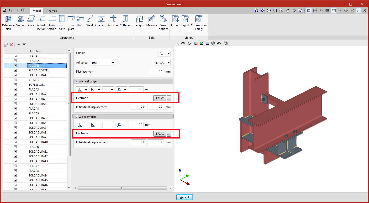
The USA element library has also been added with inch-pound units, USA (IP) and with metric units USA (M). These libraries include materials for sections and plates, the sections included in the AISC Shapes Database v.15, bolts, anchors and electrodes.

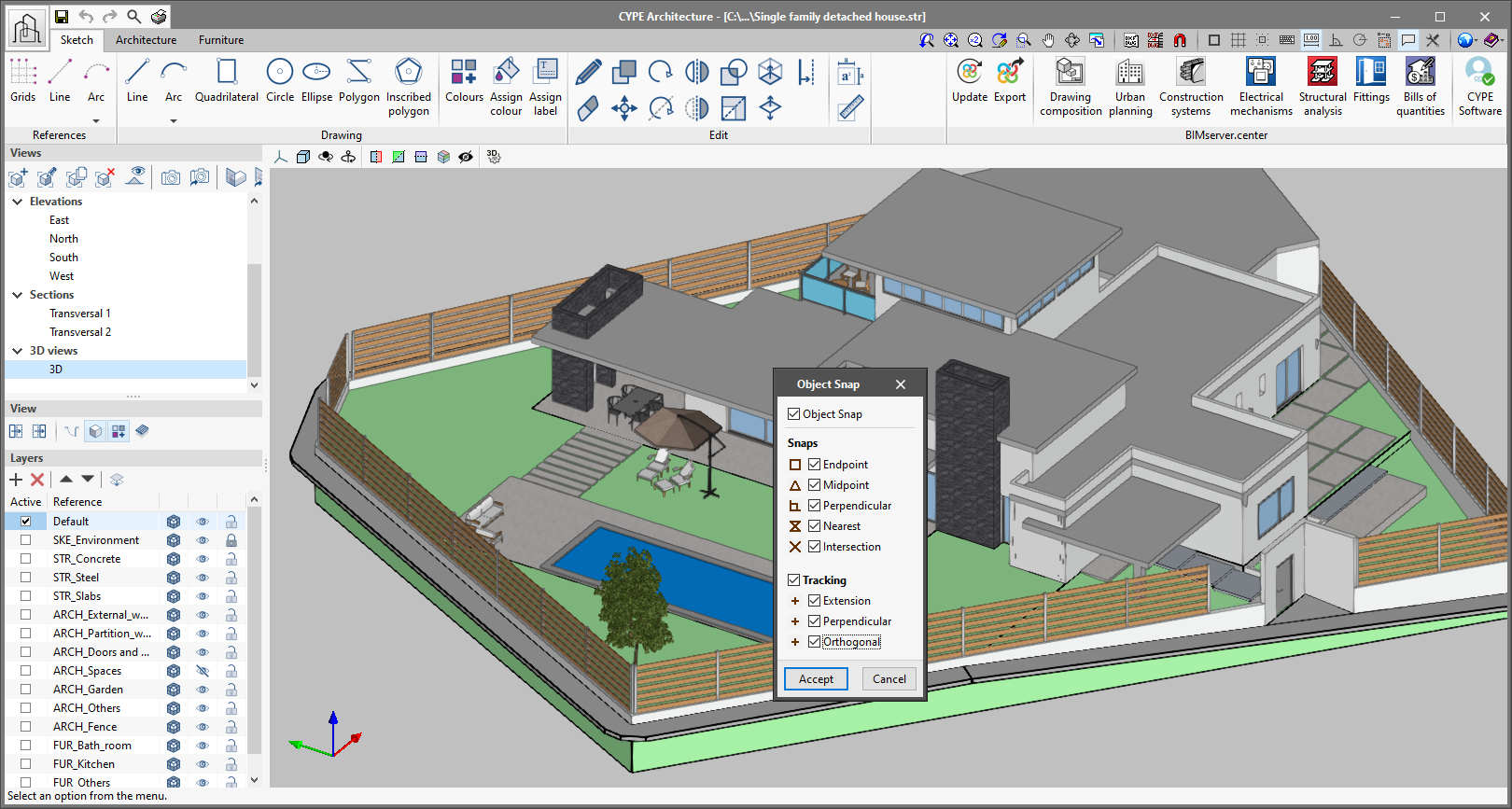
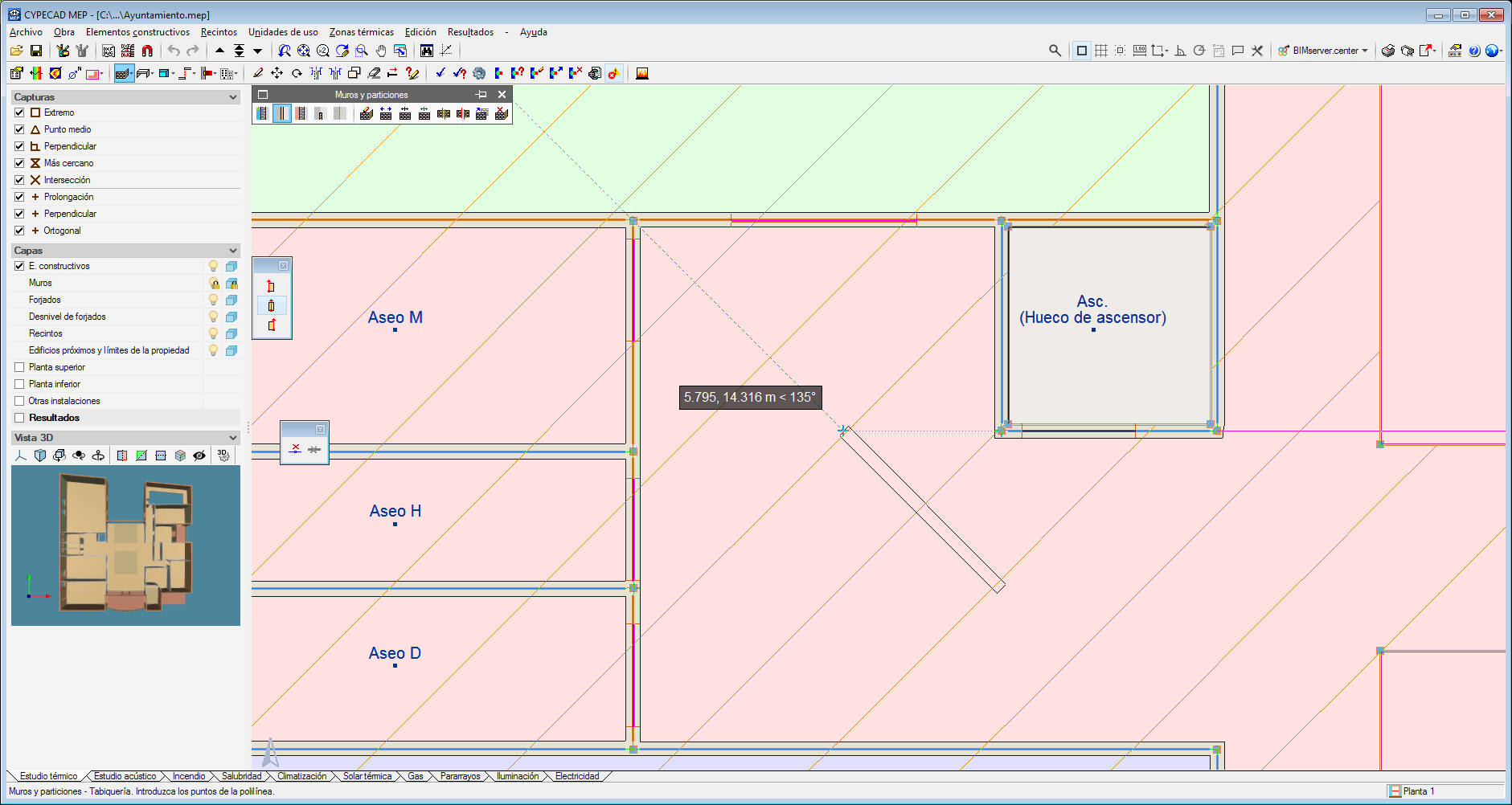
As of version 2022.b, object snap tracking behaviour has been modified in applications that have a drawing space and include this tool.
In previous versions, the alignment routes generated by all object snap points (extreme, midpoint, intersection, etc.) were visible in the drawing space. Now, users must specify in advance which points they wish to use to carry out the tracking. This way, they will avoid generating references they do not require which will slow down editing.
To add a trackable point, position the cursor over it. The added points will be shown with a cross (+) and there are a maximum of 10 selectable points; if this number is exceeded, they will be discarded based on the order in which they were added. It is also possible to remove a point from the selection by passing the cursor over its location again. Finally, when users have finished editing in the workspace, the tracking points will disappear.
The tracking points can be activated or deactivated using the F11 function key.
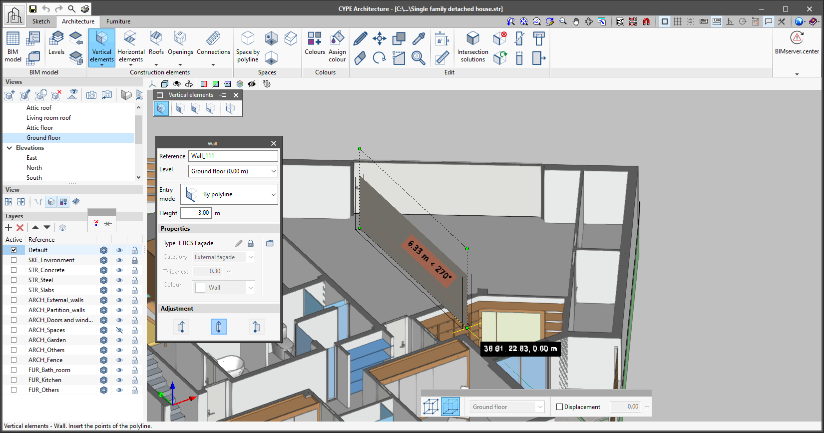
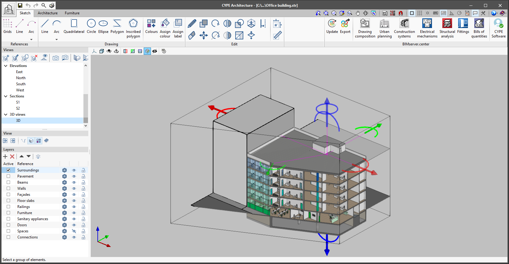
As of version 2022.b, applications with 3D drawing surroundings allow a viewing volume to be defined from the geometric envelope of the scene content. The arrows allow the viewing volume to be adjusted by moving their faces and the arches allow the viewing volume to be adjusted by means of 6 clips planes.