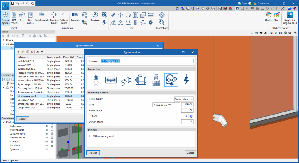
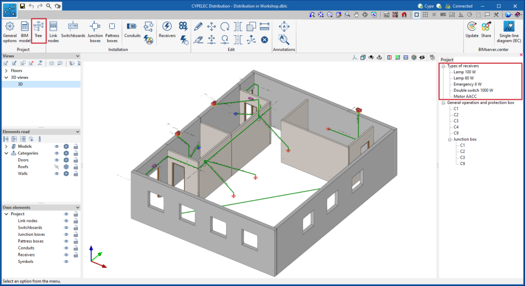
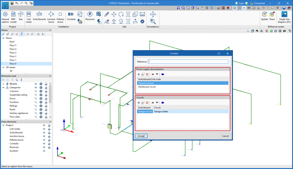
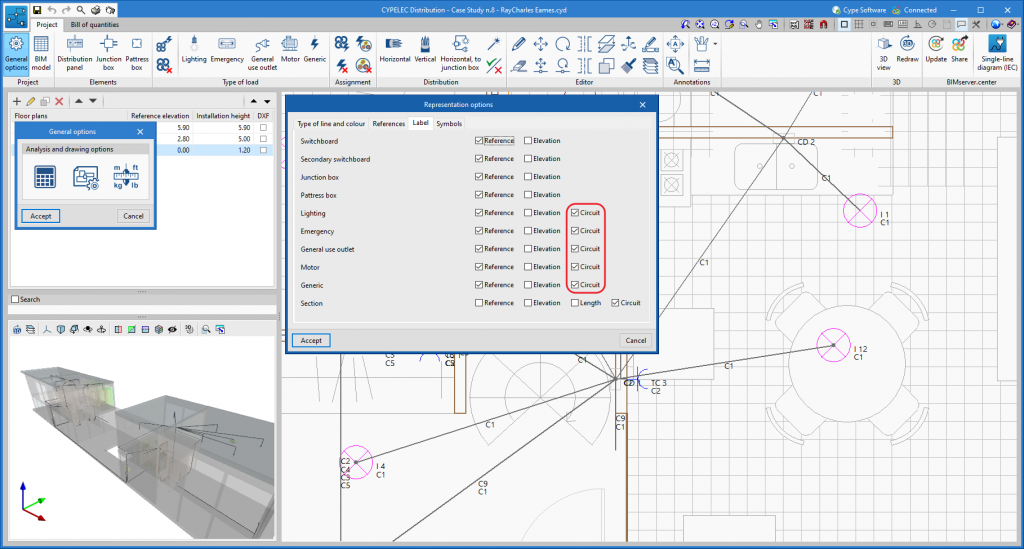
Now users can indicate the reference of the circuit that supplies power to the different receivers (lighting, emergency, general use outlets, motor and generic load).
Update history
- Solutions
- CYPELEC Distribution
- Update history
CYPELEC Distribution
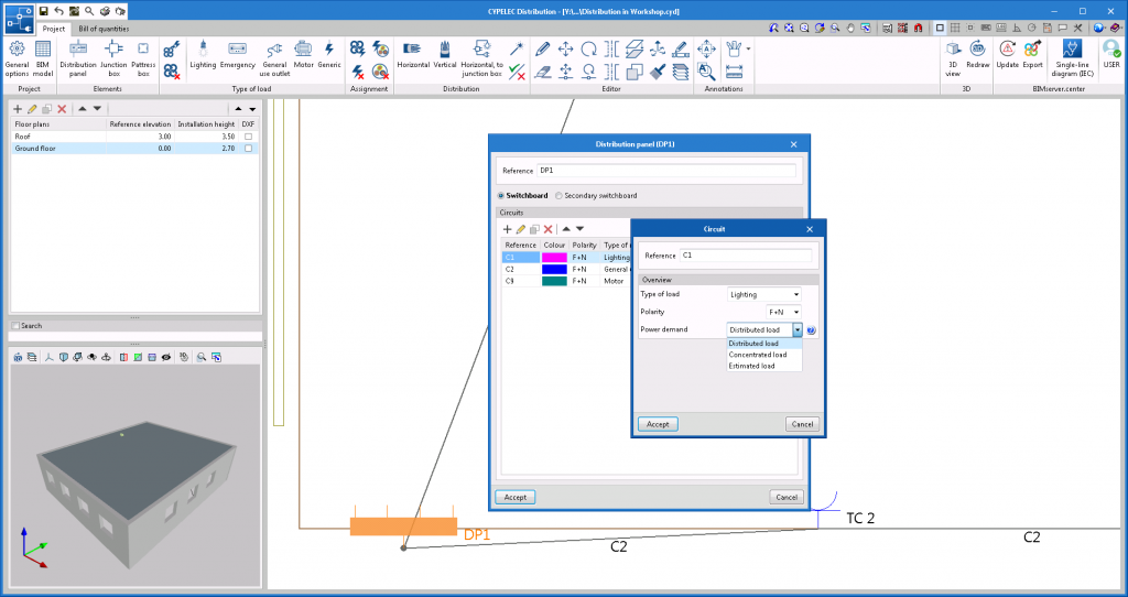
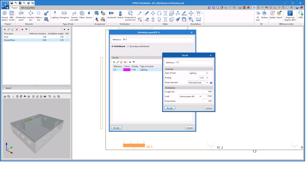
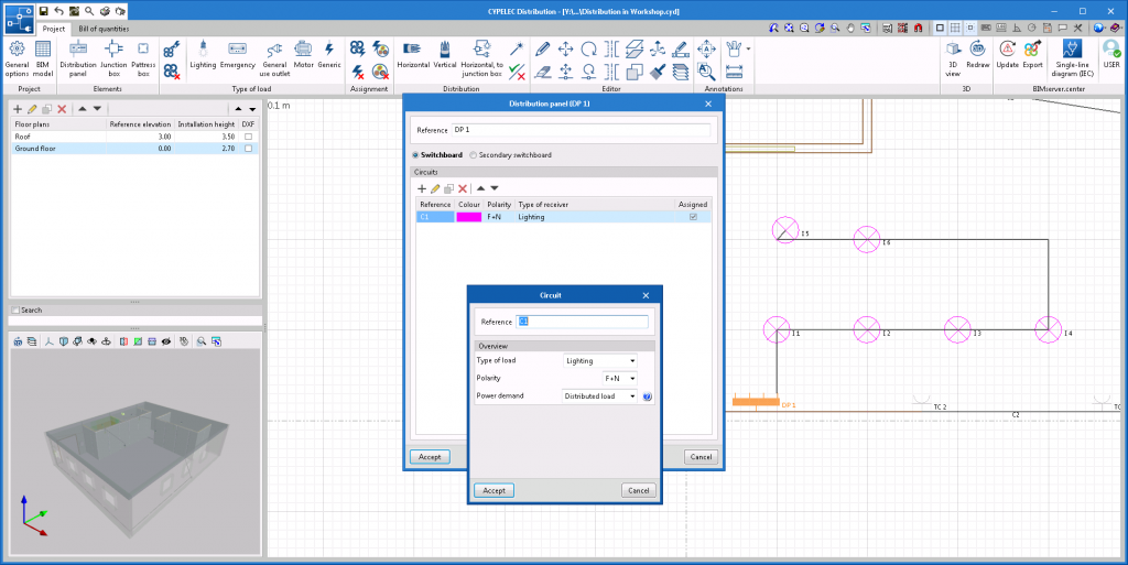
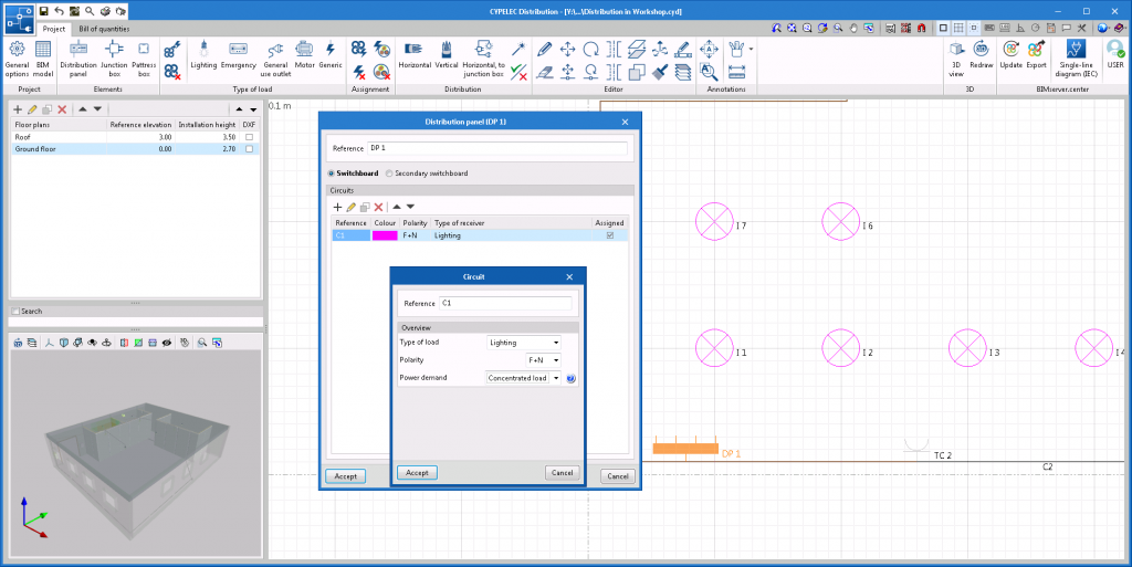
A new option for calculating the power demand and length of the circuit called "Concentrated load" has been added. Thus, the options available for the calculation of electrical circuits are as follows:
- Foreseen load. The total power and the length of the circuit are entered manually. The circuit will act as a circuit with its entire load concentrated at the end of the circuit.
- Distributed load. The power of the circuit will be given by the assignment of the loads and the length of the supply path. The circuit will act as a circuit with the loads distributed in its position.
- Concentrated load (new option). The power of the circuit will be given by the assignment of the loads and the length of the distance to the furthest load so, in this case, the supply path is not required. The circuit will act as a circuit with its entire load concentrated at the end of the circuit.
Version 2021.g of CYPE’s programs is a closing version of the 2021 version.
As well as the new features and improvements expressly indicated in each version of CYPE software, process optimisation involving internal updates for all our programs is normally included. In each revision, all programs are systematically checked and changes are made to improve their performance, therefore, we recommend that our users (in this case those of v.2021) always update their version to the latest one, regardless of the country for which they are using CYPE software or the language in which it is installed.
Similarly to the 2021.c version of CYPE Architecture, in this version (2021.e) shortcuts have been implemented in the programs CYPELEC Electrical Mechanisms, CYPELEC Distribution and CYPELEC CORE, allowing other applications to be opened in order to continue with the development of the project.
Selecting these shortcuts first exports the results obtained in the user’s current program to the BIM project and then opens the selected application, which makes it quicker to continue with the development of the project.
In this way, the user will have guided assistance which will allow them to move from program to program to complete the electrical installation. A design can be carried out starting from the architectural model right through to the analysis of the low, medium and high voltage installation without having to search for the application that continues with the development of the project.
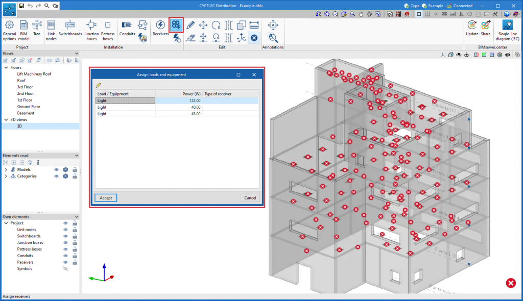
As of the 2021.e version, CYPELEC Distribution allows equipment with an electrical load that is contained in the BIM model to be read.
In this version, the import of HVAC equipment from the following programs has been enabled:
- Open BIM DAIKIN
- Open BIM BOSCH
- Open BIM PANASONIC
There are two options for importing and incorporating this equipment into the electrical installation:
- Associate the BIM model element to a new load
To carry out this option, click on the icon in the toolbar highlighted in the attached image and select the element of the BIM model to be associated.
- Associate the equipment of the BIM model to a previously defined and expected load in the electrical installation
To carry out this option, click on the icon in the toolbar highlighted in the attached image, indicate the equipment of the BIM model and finally select the load to which it will be associated.
In this case, the program checks that the sum of the power of the associated equipment is less than the expected power in the selected load.
CYPELEC Distribution allows for users to define the distribution of a three-phase circuit with single-phase loads. To define this distribution, the polarity of the circuit must be 3F+N and the supply of the loads single-phase.
This circuit is represented in CYPELEC Core, CYPELEC REBT, CYPELEC NF and CYPELEC RETIE as a three-phase distributed circuit with single-phase loads connected along its path.
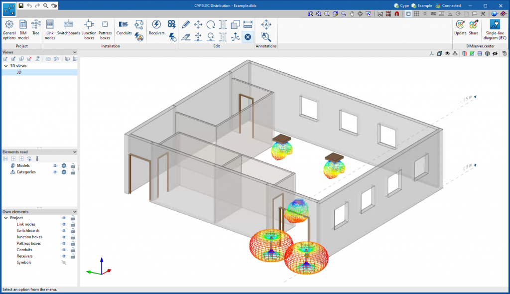
Emergency lights could already be entered in CYPELEC Distribution. As of the 2021.c version, it is possible to read emergency lights that are contained in the BIM model, for example those from CYPELEC Electrical Mechanisms (which can also be entered in this version ). This improves the Open BIM workflow.
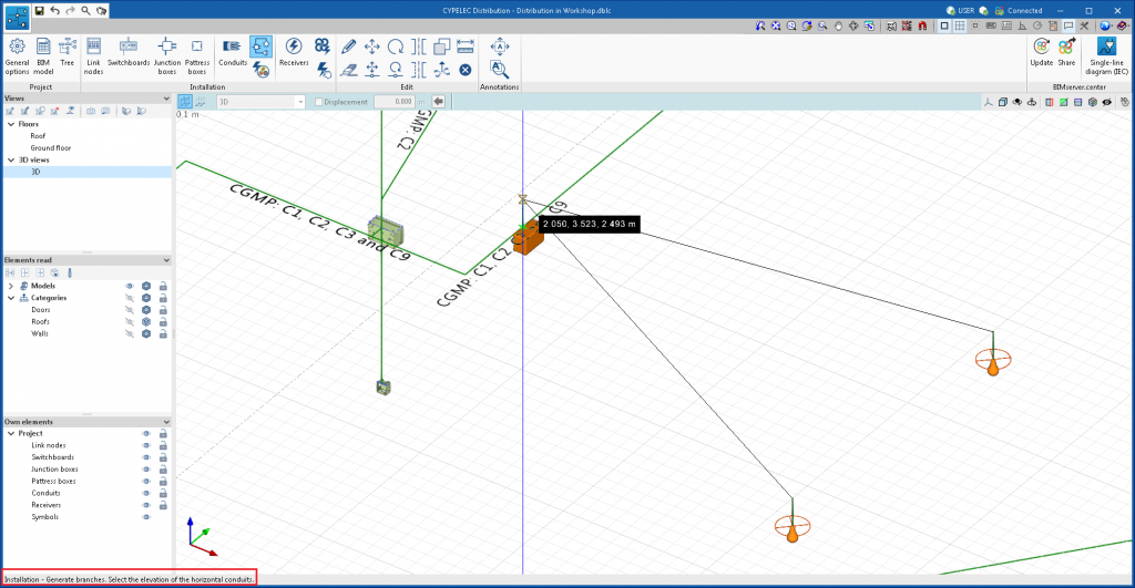
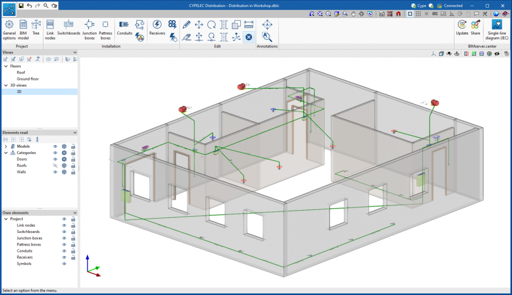
The quick connection tool between the lighting points and the junction box (located in the toolbar and labelled "Horizontal, to junction box") is extended to the selection of the pattress box. This way, time is saved in the connection, since, as well as being able to select lighting and emergency points, it is also possible to select the pattress boxes in which the switches are located.
New functionalities have been added to represent the types of lines and tags in spans and elements.
The "Representation options" icon has been added in "General options", which includes four tabs:
- Type of line and colour (new functionality). Allows users to select the colour and type of line to represent the supply lines to the subpanel and indoor circuits.
- References. Allows users to assign the default reference for the different elements.
- Tag (new functionality). Allows users to select, for each element, the properties that are to be represented on-screen and later on the floor plans.
- Symbols. Allows users to edit customised symbols, which can then be assigned to different elements.
The mechanism box can be entered in CYPELEC Distribution. In the 2021.a version, the program can read mechanisms such as switches, commutators, crossings, etc., contained in the BIM project, in such a way that the program places its mechanism box. This way, clients do not have to enter it manually and can complete the path of the electrical distribution.
Programs like CYPELEC Electrical Mechanisms allow users to enter electrical mechanisms and export this information to the BIM project.
The “Bill of quantities” tab has been included in the four programs (CYPELEC REBT, CYPELEC RETIE, CYPELEC NF and CYPELEC Distribution). Now, users have tools to generate and manage the bill of quantities of the elements that have been entered.
More information in “Bill of quantities” tab in project phase Open BIM applications.
A new project example has been included: "Electrical distribution in training center". This project represents the electrical distribution in a training center that contains a single switchboard, and several secondary panels.