Update history​​

CYPELEC Networks

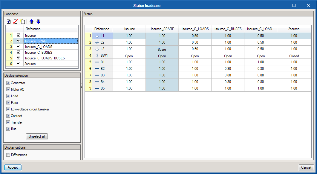
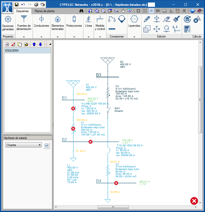
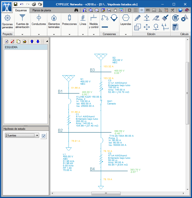
The definitions of status loadcases were included in the 2018.c version of CYPELEC Networks.

Now, in the 2018.e version, a powerful tool has been introduced to analyse all the loadcases that have been defined, which allows users to view the results of all the loadcases quickly and clearly. This tool allows users to obtain a global view of the results provided by the load flow analysis for all loadcases and aids them to adopt solutions to comply with the corresponding loadcases.

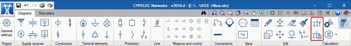
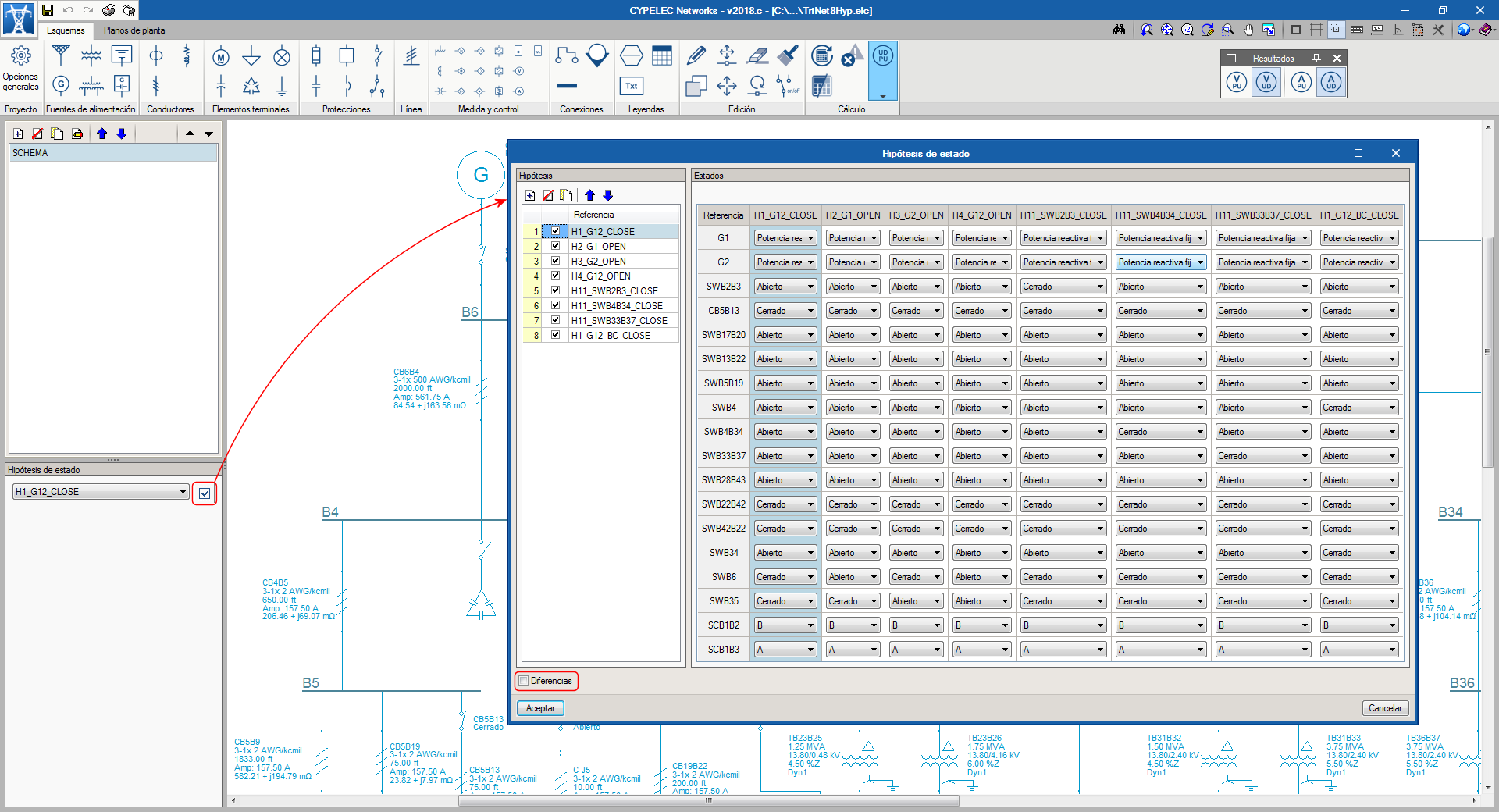
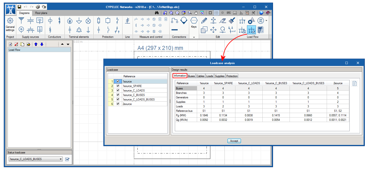
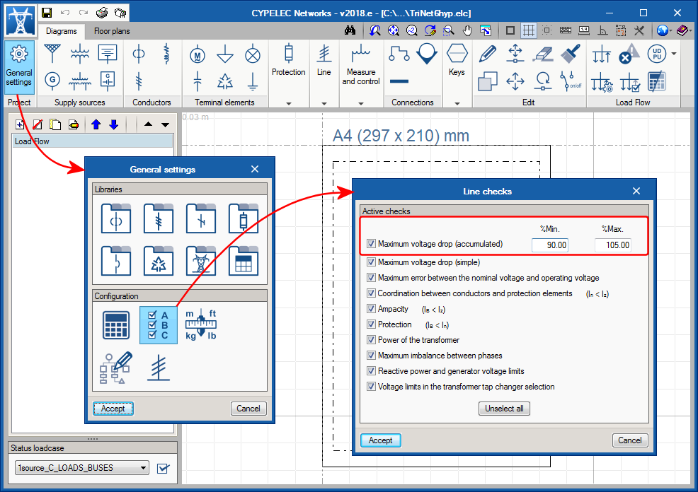
This tool is selected by pressing the “Loadcase analysis” button  located in the “Load flow” section of the toolbar, which opens a panel containing the loadcases that have been defined and their corresponding analysis results, all of which is organised in several tabs:

  • Information tab
    Shown in this tab are the design properties of the loadcases selected on the left, such as the number of buses, branches, generators, supplies and loads each loadcase consists of. The initial reference bus for the analysis of the load flow calculation is also specified as well as the resultant generation power.
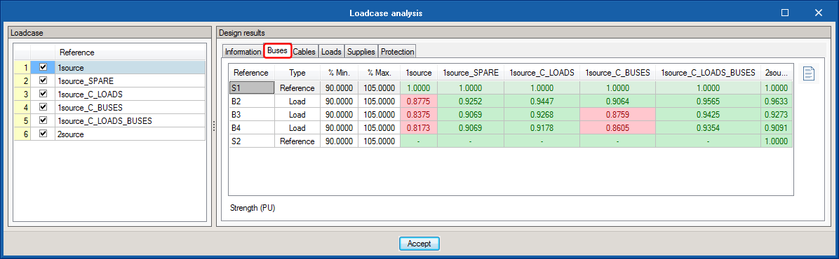
  • Buses tab
    The resultant voltage values in PU in each bus for each loadcase are transferred here and are compared with the allowable accumulated voltage drop values that have been defined in General settings.
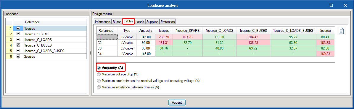
  • Cables tab
    The “Cables” tab is sub-divided into 4 sections:

    Ampacity
    Shows the resultant design current that flows through each cable or transmission line, and is compared with its ampacity.

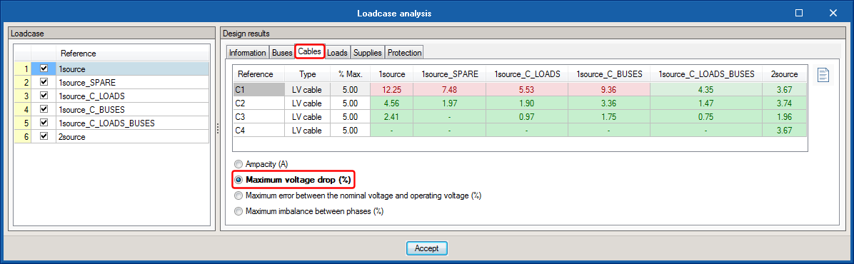
Maximum voltage drop
Shows the resultant voltage drop due to the impedance and admittance of the cable or transmission line, and is compared with the maximum voltage drop that has been introduced in the Edit panel.

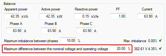
Maximum error between the nominal voltage and operating voltage (%)
Shows the percentage resultant error between the nominal voltage and operating voltage, and it is compared with the value that is introduced in the Edit panel of the cable or transmission line.

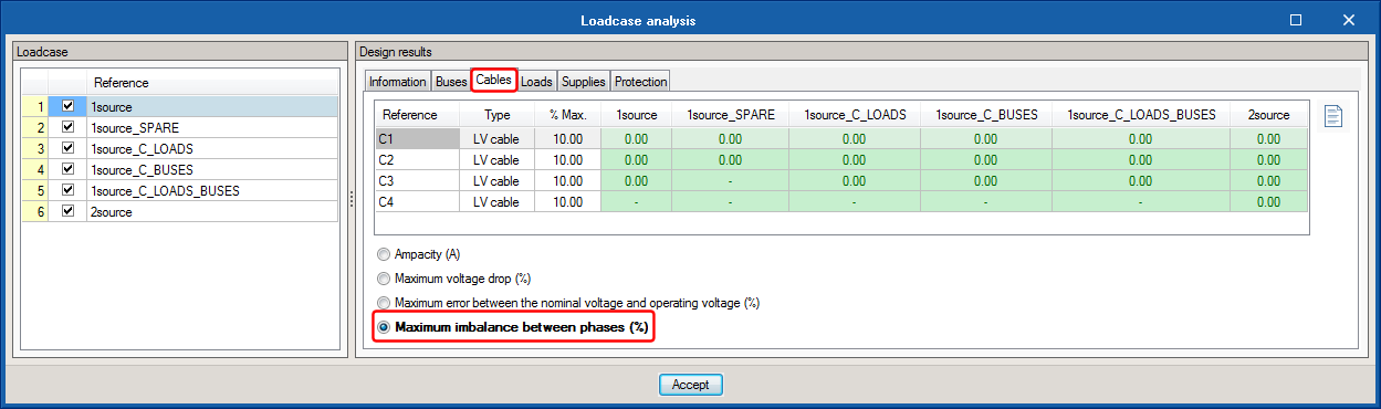
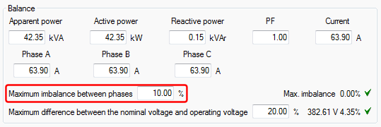
Maximum imbalance between phases (%)
Shows the percentage resultant imbalance between the most loaded phase and the least loaded, and is compared with the maximum imbalance value between phases that has been introduced in the Edit panel of the cable or transmission line.
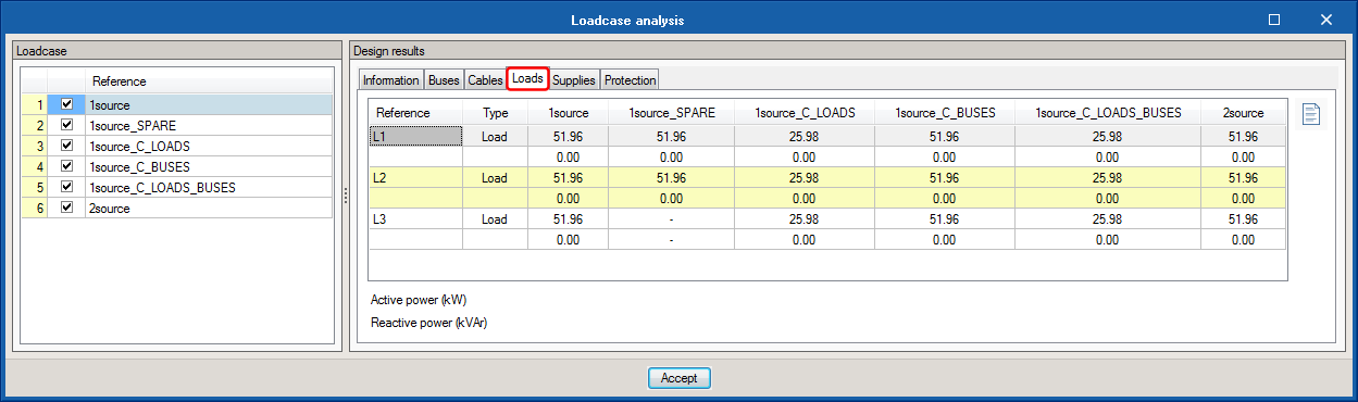
  • Loads tab
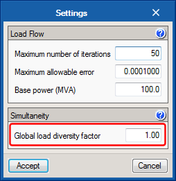
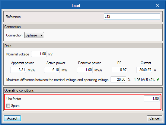
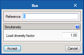
    Here, represented for each loadcase, are the values of the active and reactive power of the loads, which are affected by the use and simultaneity criteria specified for each loadcase.
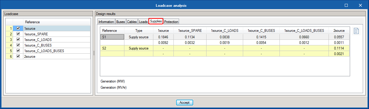
  • Supplies tab
    The resultant values of the active and reactive power generated by each supply are displayed for each loadcase, in accordance with the load flow calculation.
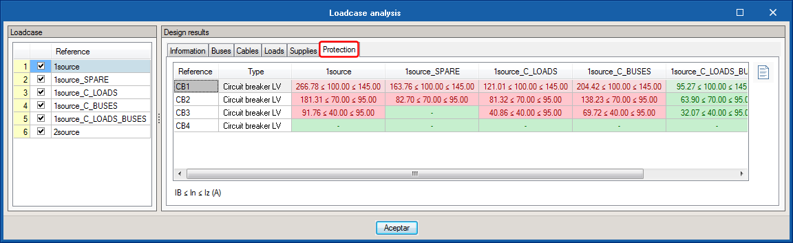
  • Protection tab
    Also for each loadcase, represented in this tab is the check that relates the nominal or protection regulating current, with the design current of the line and ampacity of the cable it protects.

Allowable current tables of the IEC 60364-5-52 have been added to the list of tables described in the NEC to be used in the ampacity calculation of ANSI cables.

This way, depending on the chosen reference installation method and the properties of the selected cable, the program will provide the allowable current of IEC conductors. This improvement allows users to use the program for European installation and for countries that use square millimetre sections.

The program includes Prysmian cables in its library, so users have cable families of both standards (ANSI and IEC) available.

The example “TriNet6Hyp” has been included as an example, which includes six design loadcases in an electrical installation.

The 2018.d version of CYPELEC Networks includes substantial improvements in the window that displays the status loadcases:

  • The information is displayed as a table
  • Its speed has been increased
  • As well as being able to view the state conditions of fuses, switches, contacts and operating regimes of generators and motors, the diversity conditions of buses and use of loads are included.
  • To manage the important amount of information due to a large number of loadcases and elements, a filter tool has been added to the window to select the equipment or element category to be viewed.

After the load flow calculation process, arrows are displayed in the single-line diagram, which display the direction of the current as well as its results.

The load flow calculation icon is substituted for a more representative icon, and includes quick access icon to its design options, amongst which is the possibility to define the global diversity factor.

Users can now define a global diversity factor for all the installation. The global diversity factor is applied to all buses and affects the calculation of the flow of loads of the installation.

The 2018.d version includes the option to define use factors for loads.

Use factors for loads are applied to each load independently and affect the calculation of the flow of the loads of the installation.

Loads can also be defined as a “spare load”, which are not considered in the calculation of the load flow.

The 2018.d version includes diversity factors in buses. This factor is applied to loads that are directly connected and affect the calculation of the flow of the loads of the installation.

From the first version of CYPELEC Networks, when a two winding transformer and a three winding transformer are edited, users can configure and the select the tap changer with the aim to regulate the voltage in the buses connected by the transformer.

After the analysis process, it may occur that the selection of the tap changer may cause the voltage of the controlled bus to lie outside the maximum values specified in the panel. As of the 2018.c version, when this case arises, the program can emit a warning to tell users to carry out a check. This warning is emitted if the new check “Voltage limits in the selection of the transformer tap changer” is activated, which is done in “General settings” > “Line checks”.

To manage the operation status of the installation elements, the 2018.c version includes the definition of the status loadcase. These loadcases define the status conditions of:

  • Simple contacts and commutation contacts
  • Fuses and switches
  • Operation regimes in motors
  • Operation regimes in generators

From the start, the circuit diagram is assigned to one loadcase (which can be unique) and is referenced on the left of the user interface.

Using the icon next to the reference of the visible loadcase, the loadcases can be generated in a panel created for this purpose and in which the status of all the previously mentioned elements are listed. Furthermore, the status can be changed directly in this panel.

The panel allows users to select the loadcase which is to be listed, as well as an option to only view the status differences of the elements of the selected loadcases.

CYPELEC Networks is now available to be downloaded at the BIMserver.center platform.