An option has been introduced to display the results obtained at each design point of the zones defined in CYPELUX. This way, as well as being able to visualise the representation of the contour lines and contour maps on plan, it is also possible to inspect the value of each sensor used by the program.
Update history
CYPELUX
Display numerical results on the floor plan
- Published on
- 2017.h
Rendering of the natural light scene
- Published on
- 2017.g
Calculation of the daylight factor
Thanks to the daylight analysis that has been included in CYPELUX, it is now possible to determine the daylight factor values for each project space. The daylight factor expresses the ratio between the illuminance at a point indoors due to natural daylight and the illuminance it would have if there were no obstructions. This coefficient is indicative of the usage level of natural light.
- Published on
- 2017.g
Calculation of the illuminance produced by daylight
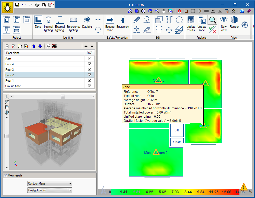
As of the 2017.g version, CYPELUX incorporates the calculation of the illuminance produced by natural light. To obtain these values, the CYPELUX project must be associated with a BIM model containing, at least, the geometric definition of the building.
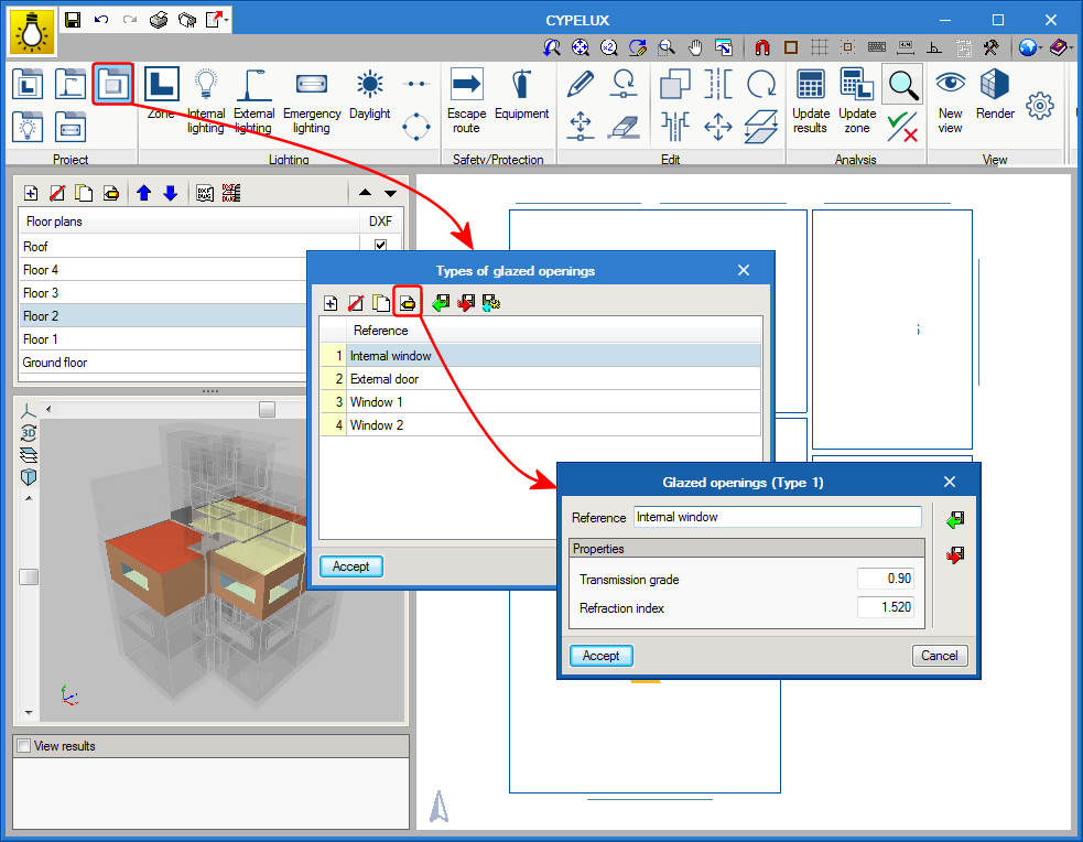
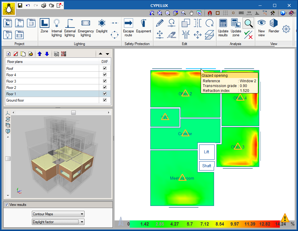
A library is also included in the program, which can be accessed from the toolbar, and contains the types of windows and skylights that are present n the project. Users can indicate the “Transmission grade” and “Refraction index” of the glass.
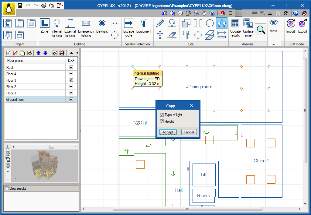
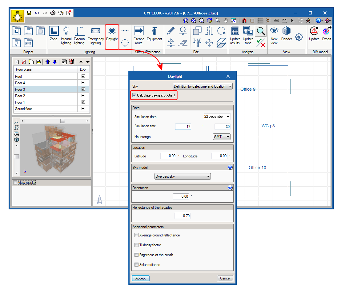
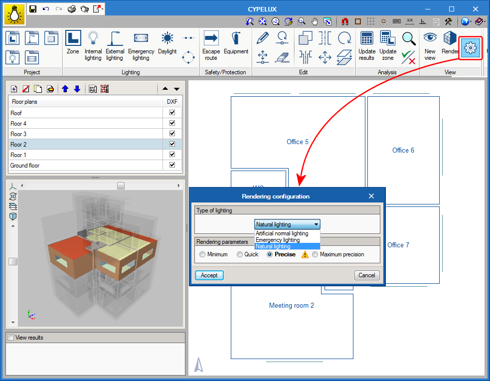
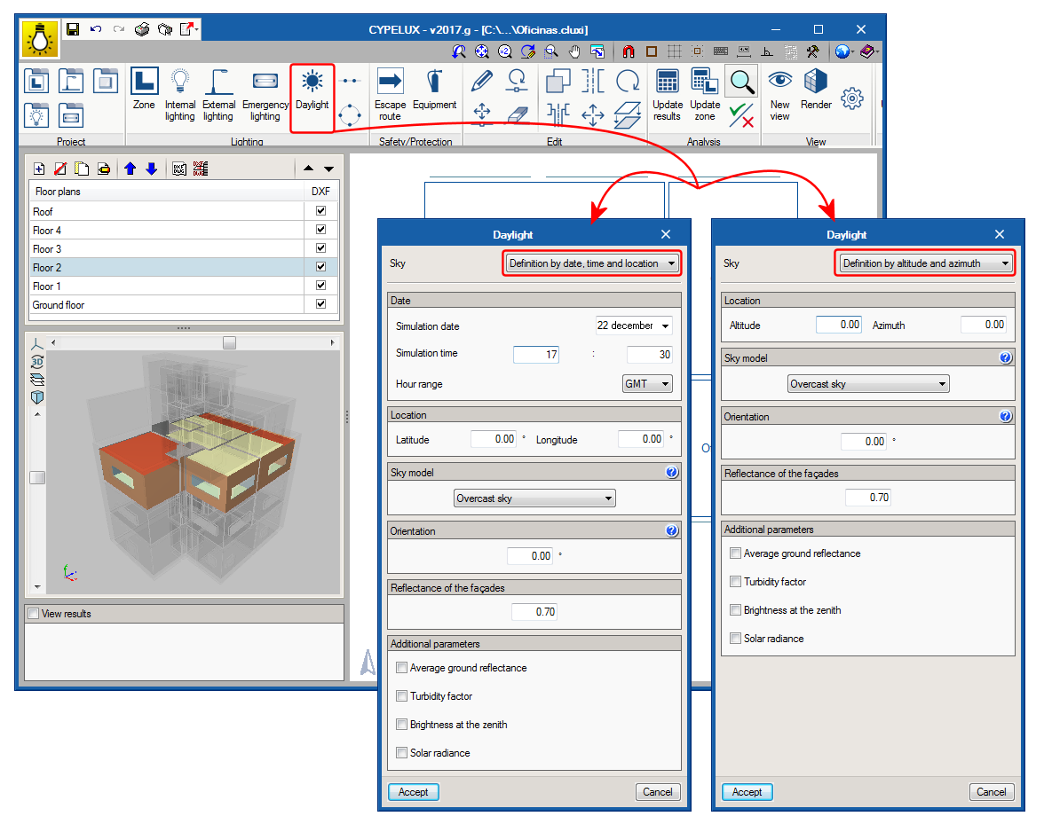
To be able to launch the analysis, as well as having to specify the properties of the glazed openings, the light conditions must be described using the “Daylight” option in the toolbar of the program. Specified in this panel are the daylight parameters such as the type of sky based on the CIE standard, the location of the building and its orientation, which can be obtained from the BIM model, if it has been defined in it.
- Published on
- 2017.g
Autosave
The autosave option has been implemented in the 2017.e version of CYPELUX. The autosave can be carried out in two ways:
- Automatically save every... minutes
Save the project automatically in the indicated time interval. - Save after analysing or designing
Save the project automatically upon analysing the lighting installation.
Neither option is activated by default. Hence, users must activate the option they wish to apply.
- Published on
- 2017.e
Scene rendering
Thanks to the inclusion of the Radiance analysis motor in CYPELUX, users can represent the lighting effects produced by the installation of normal or emergency lighting on a precinct.
To do so, the View option has been added to the program. This option contains three new buttons:
- New view
It is possible to introduce different points of view on the floor plan and configure its properties. - Render
Using this option, users can indicate which view is to be rendered.
- Rendering configuration
When rendering takes place, users can choose whether the lighting to be viewed is normal (internal and external) or emergency lighting, as well as the degree of precision of the scene.
- Published on
- 2017.e
New analysis motor (Radiance)
As of the 2017.e version, CYPELUX uses the Radiance analysis motor (developed by the Lawrence Berkeley National Laboratory) to carry out the lighting analyses for normal and emergency lighting. This new analysis methodology provides more precise results for indirect lighting, carry out the discretisation of non-point light sources and view realistic light scenes.
- Published on
- 2017.e
Copy elements from one floor to another
With the 2017.c version, users can copy elements from one floor plan to another using a new button located in the Edit menu of the toolbar. Users must choose which CYPELUX entities are to be duplicated (amongst the options available are the lights which make up the lighting installation and safety/protection elements, such as evacuation routes and equipment) to then choose on which floor they must be duplicated.
This tool, which has already been implemented in other programs, such as CYPETHERM HVAC, is of great importance when trying to reproduce the same distribution on different floors of a BIM model, where floor plans are defined by the geometry of the IFC.
- Published on
- 2017.c
Import lights
As of the 2016.l version, users can add lights from files with “IES” format (standard format in North America for photometric data) or “LDT” format (standard format in Europe for photometric data) by dragging these files into the CYPELUX window. This way, light catalogues from manufacturers are more easily introduced in CYPELUX.

- Published on
- 2016.l
Automatic distribution of lights
The program can now automatically distribute the lights to follow linear or circular distribution paths:
- Linear distribution
For the linear distribution, users can choose the number of lights to be placed, their height and orientation. Three alignment types with respect to the reference line have also been included. - Circular distribution
As occurs with the linear distribution, users can choose the number of lights to be placed, their height and orientation The initial angle of the distribution can also be edited.
- Published on
- 2016.l
Illuminance units (fc)
“Foot-candle” photometric measurement units, widely used in countries such as the USA, have been included in the program as an optional way of measuring the illuminance levels obtained after the analysis.
- Published on
- 2016.l
New types of lamps and lights
- Published on
- 2016.l


