Update history​

CYPETHERM HVAC

Duct dimensions

In previous versions, the sizing tables for rectangular and circular ducts which the program used to design these elements, were defined in the “Design options for ducts” menu (General settings > Options > General options). As of the 2018.i version, these tables are defined in the material libraries of the ducts (General options > Libraries > Material types for ducts > edit or add a material).

This way, the sizing tables can differ depending on the material that is used.

Improvements in panels and tools

Units panel

Grouping of measurement units in the units configuration panel is organised in the “Primary measurement units”, “General measurement units”, “Thermal measurement units” and “Drawings” tabs. This grouping already existed in previous version but all the units were displayed in the same table, which generated a very long panel.

Separate blocking of the width and height of ducts

As of the 2018.g version, users can separately block the height and width of rectangular ducts. Now, one of the two dimensions is fixed so it is not modified during the analysis. In previous versions, when the duct was blocked, both dimensions were blocked at the same time.

Introduction of elements by lengths

The tool that marks the distance to nearby objects when an element is introduced has been improved.

For example, when a grille is moved along duct while it is being placed, a dimensions line appears that indicates the distance to the end of the duct. In previous versions, only the numerical value of the distance appeared.

DAIKIN VRV systems

As of the 2018.e version, DAIKIN VRV systems can be introduced in the “Circuit diagram” tab. CYPETHERM HVAC generates a justification report of the designed system.

Copy format in circuit diagram

The “Assign” tool  has been added in the Flow diagrams tab of CYPETHERM HVAC. This way, users can quickly copy the length of one pipe to others. Once this tool is activated, the pipe whose length is to be copied is selected using the left mouse button and then, the pipes to which the length is to be assigned are selected with the same mouse button (one by one or using a capture window).

Warnings of flow in the wrong direction

Both horizontal and vertical ducts are introduced with an air flow direction which depends on the initial and final point when the horizontal ducts are drawn or the initial and final elevation in the case of each vertical duct. Using the “Invert the air flow direction in ducts” tool , users can change the direction of flow.

As of the 2018.e version, if the direction of flow indicated by users is incorrect, the program detects this and emits a warning message at the end of the analysis process.

Floor heights and installation height

As of the 2018.e version, the height between floors and the elevation of each floor (which is obtained from the BIM model) are represented in the list of floor plans which is located in the top left of the program screen.

Furthermore, using the edit button of this list , users can define the installation height of the ducts.

Vertical ducts

The introduction and design of vertical ducts has been implemented. From the properties panel, users can indicate up to what level they are to reach.

On plan, the direction of the flow in the vertical ducts is represented by a cross when it in a downward direction and a circle when the flow is in the upward direction.

Program downloads on the BIMserver.center platform

The following CYPE programs are available to be downloaded from the BIMserver.center platform:

  • CYPELUX CTE
  • CYPELUX EN
  • CYPELUX HQE
  • CYPELUX LEED
  • CYPELUX RECS
  • CYPETHERM EPlus
  • CYPETHERM RT2012
  • CYPETHERM COMETH
  • CYPETHERM REH
  • CYPETHERM RTExistant
  • CYPETHERM RECS Plus
  • CYPETHERM C.E.
  • CYPETHERM LOADS
  • CYPETHERM HVAC
  • CYPELEC REBT
  • CYPELEC NF
  • CYPELEC CT

These programs are also available on the main CYPE program menu, which is installed with the file that can be downloaded from the Download Area of the CYPE website.

TOSHIBA 1x1 Split systems

The 2018.a version allowed users to define TOSHIBA Multi-split systems. These systems could consist of an outdoor unit and between 2 and 5 indoor units (cassette, duct, wall or floor).

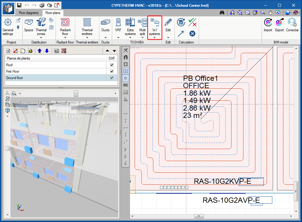
Now, with the 2018.b version, the program incorporates TOSHIBA 1x1 Split systems, which consist of an outdoor unit and an indoor unit (wall or floor).

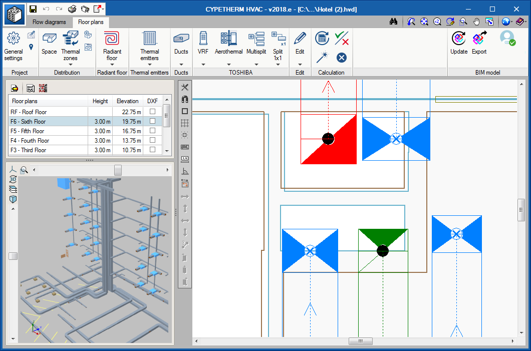
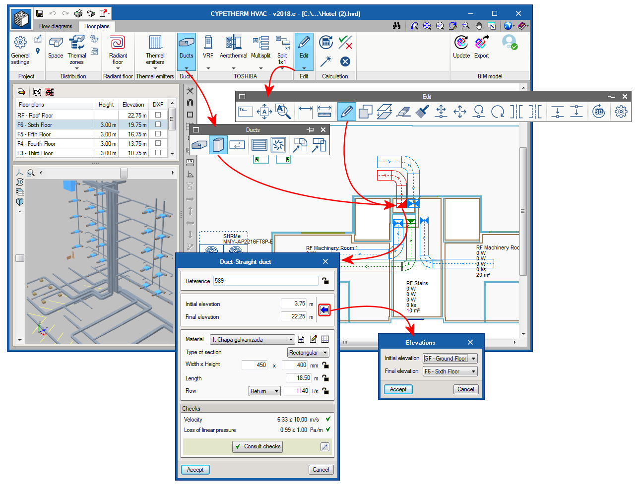
The design procedure is similar to that used for the Multi-systems included in the previous version. For 1x1 Split systems, in the “Floor plans” tab, users place the indoor unit (wall or floor unit) in a space and the outdoor unit on the façade or roof of the building. Unlike Multi-split systems, the two units of the 1x1 Split systems are placed together in the “Diagrams” tab, since they appear joined using cooling fluid pipes.

Upon designing, the program automatically checks the indoor and outdoor equipment that has been placed, as well as the pipe diameters.

Regarding the results, the program generates, as well as the drawings, a report of the design of the system and its quantities.

Please note that for CYPETHERM HVAC to be able to design a Multi-split system or TOSHIBA 1x1 split system, users must have acquired the permits for “Direct expansion systems” in their user license.

Quantities of radiant floor pipe rolls

In the 2018.a version, CYPETHERM HVAC incorporates a new tool to generate and manage the quantities of the radiant floor pipe rolls and their sub-division in circuits.

Users can accept that proposed by the program, modify it or create their own distribution from the beginning. To do so, the tool incorporates an automatic generation assistant and the tools required to create or modify the distribution of the rolls. It also manages the circuits so that no quantities are duplicated due to manual modification. It displays the length of each circuit at all times and the length remaining in each roll.

The quantities generated by this tool are included in the results report as well as in the quantities report.

Text sizes in diagrams and drawings

The icon “Drawing options” has been implemented in the “General settings” dialogue box, using which a panel can be accessed in which the height of the texts of the Circuit diagram and Floor plans can be defined. These values will affect the texts of the diagram and drawing on-screen and when they are printed or exported to files of the available formats. The standard sizes in accordance with ISO 3098-0:1997 Technical Product Documentation are the following: 1.8 mm, 2.5 mm, 3.5 mm, 5.0 mm, 7.0 mm, 10.0 mm, 14.0 mm, 20.0 mm.

For Floor plans, the height of the text and scale of the drawing is defined. The scale of the drawing will not affect the height of the text that has been defined.

Grilles library

A library of discharge, return and extraction grilles with generic values has been added.