Update history​

CYPETHERM HVAC

Radiant floor

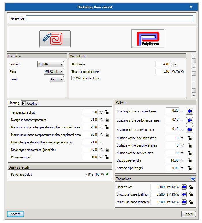
Polytherm radiant floor

As of the 2017.f version, Polytherm radiant floor systems are incorporated in the program. Users can now select any of the systems offered by Polytherm in their current catalogue.

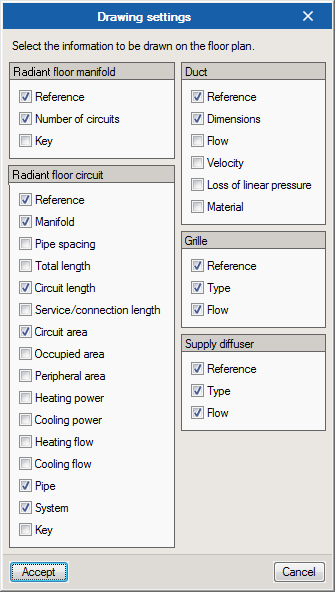
Circuit and manifold tags

Users can now configure the tags of the radiant floor circuits and manifolds. This way, users can decide what data is to be included in the tags generated by the program (they are displayed on screen and on the installation plans) for these elements of the installation.
Ducts

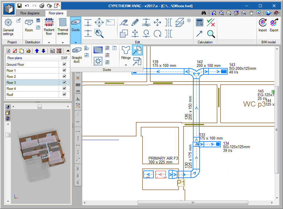
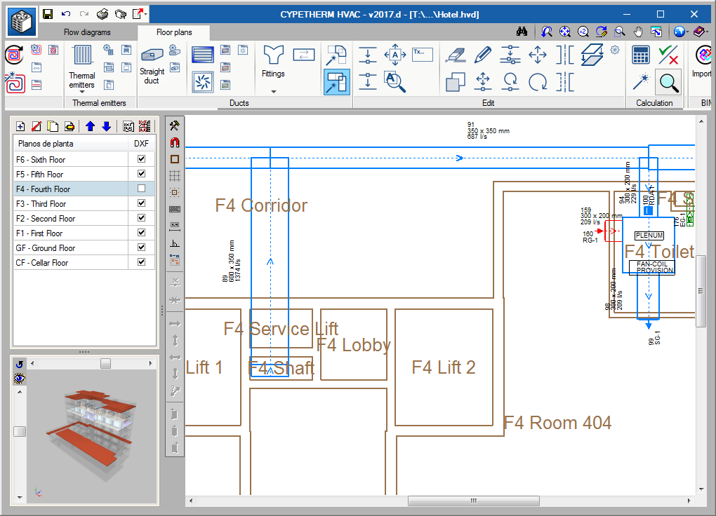
Configuration of the generation of duct fittings

When users select the “Generate fittings” button, a new dialogue appears where the generation process of the duct ties can be configured:

  • Delete existing fittings
    By selecting this option, any fittings that were placed before the generating process are deleted. The new fittings are generated in accordance with the dimensions of the spans they have to connect.
  • Generate in all the floor plans

Intersections between ducts and columns

If there are any intersections between the columns of the BIM model and the ducts of the installation, the program will warn users with an error message.

Thermal emitters

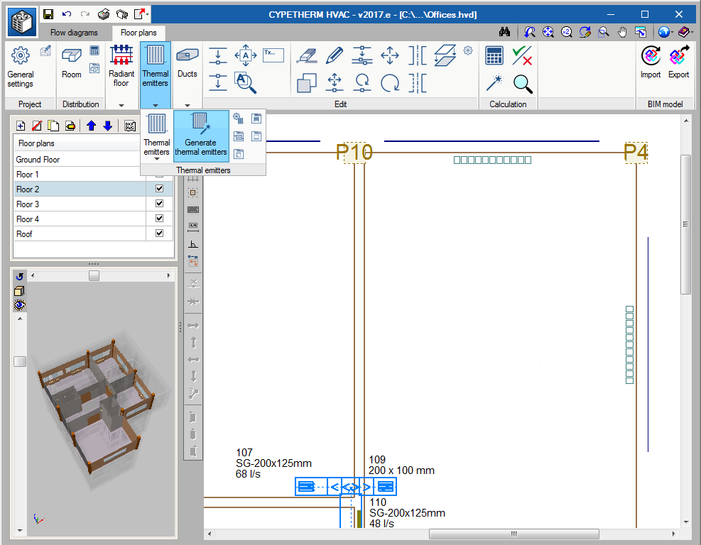
Detection of windows of the BIM model during the automatic generation of radiators

In the 2017.e version, the “Generate thermal emitters” option has been implemented. If this button is selected, the program provides a radiator below each window, by default, thanks to the interpretation of the BIM model.

The radiators that are placed are not designed. It is not until users press the design button that the program will select the number of elements each radiator requires to cover the heating thermal load.

Description of the thermal parameters of the emitters

The definition of the thermal emitters has been simplified by substituting the “average temperature”, which was indicated up to now, with the entry and outlet temperatures.

Internal design temperature in the emitters

The thermal emitters adopt the internal design temperature of the precinct in which they are located. Users can block this temperature in the emitters.

Radiant floor

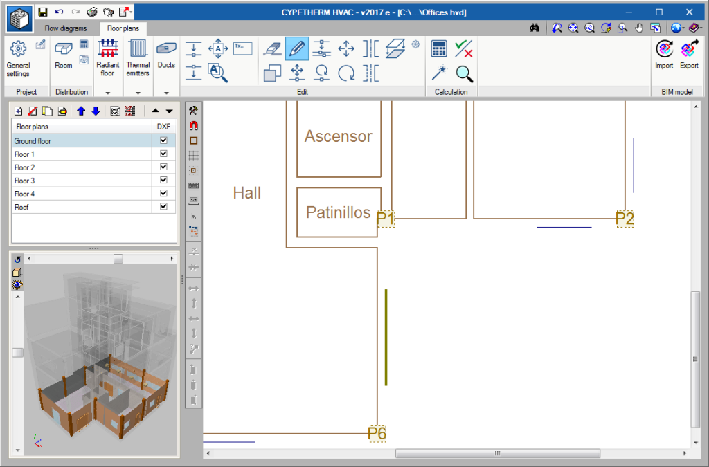
Detection of doors and columns of the BIM model during the automatic generation of the radiant floor

As of previous versions, using the “Generate circuits” button, the program detects all the spaces for which a design heating temperature has been defined, and automatically generates the radiant floor circuit. As of this version (2017.e), the generating process interprets that the columns in the BIM model are obstacles and the doors are an entry point for the pipes of the radiant floor.

Remember, once the radiant floor has been generated, the installation must be designed so the program can calculate the area and power generated by each circuit.

Manifold flow meters

Users can use flow meters in the hydraulic balancing of the manifolds of the radiant floor; only balancing valves were available up to now.

Circuit-manifold connection pipes

The behaviour of the connection pipes of the radiant floor (from the circuit to the manifold) has been improved. Now, the thermal contribution in the precinct through which these pipes go through is accounted for and graphical representation problems have been solved.

BIM model

Import columns, doors and windows

Columns, doors and windows defined in the IFC model are now imported to CYPETHERM HVAC. This feature not only aids in understanding the architectonic model on which the installations are being designed, but they are also taken into account when inserting air conditioning equipment.

Delete duct fittings

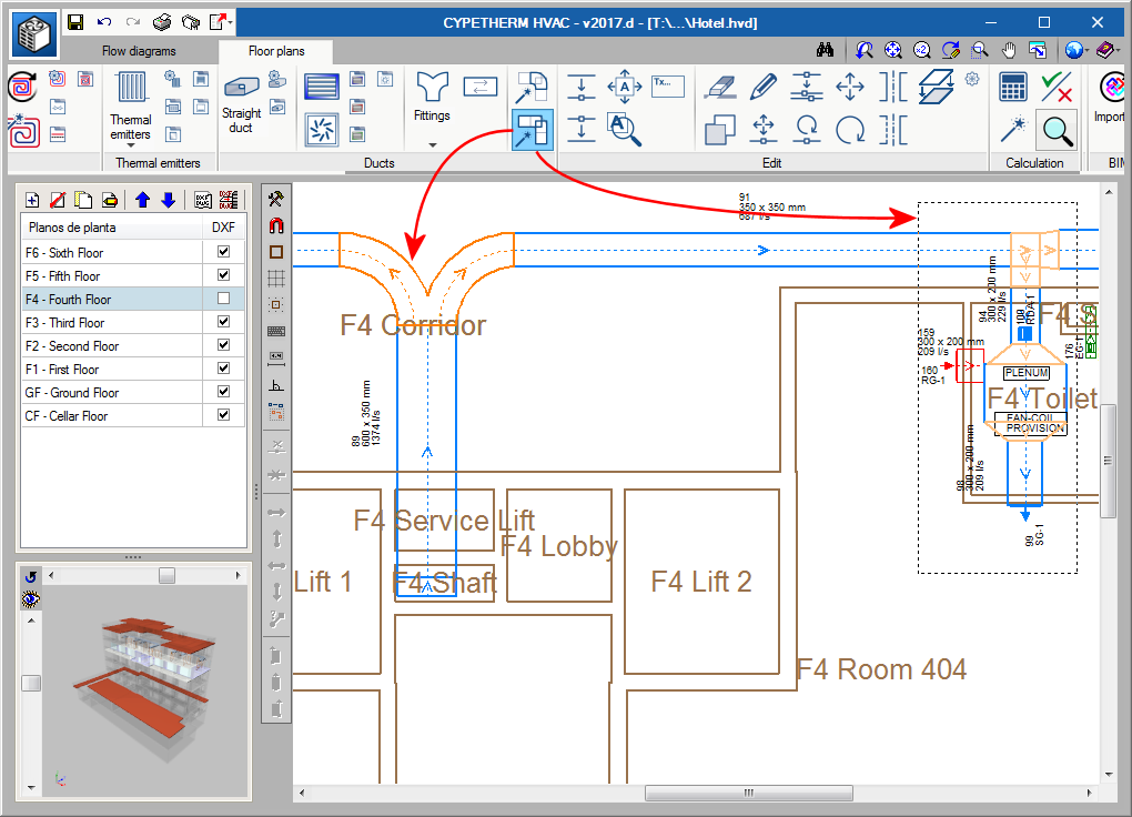
Below the button users can use to generate duct fittings  (implemented in the 2017.c version), a new button has been added to delete fittings . Two steps must be taken to delete fittings:

  • Select the fittings to be deleted
    Using the left mouse button, the fittings to be deleted can be selected one by one, by dragging a capture window to select them, or by combining both methods.
  • Confirm they are to be deleted
    Once the fittings to be deleted have been selected, they are deleted by clicking on the right mouse button.

Automatic generation of references for network elements

As of the 2017.d version, CYPETHERM HVAC generates, during the analysis process, the references of all the network elements (duct, fittings - elbows, branches and transitions, grilles), so that they can be identified on plan and in the ducts report.

Fan coils. Design and selection

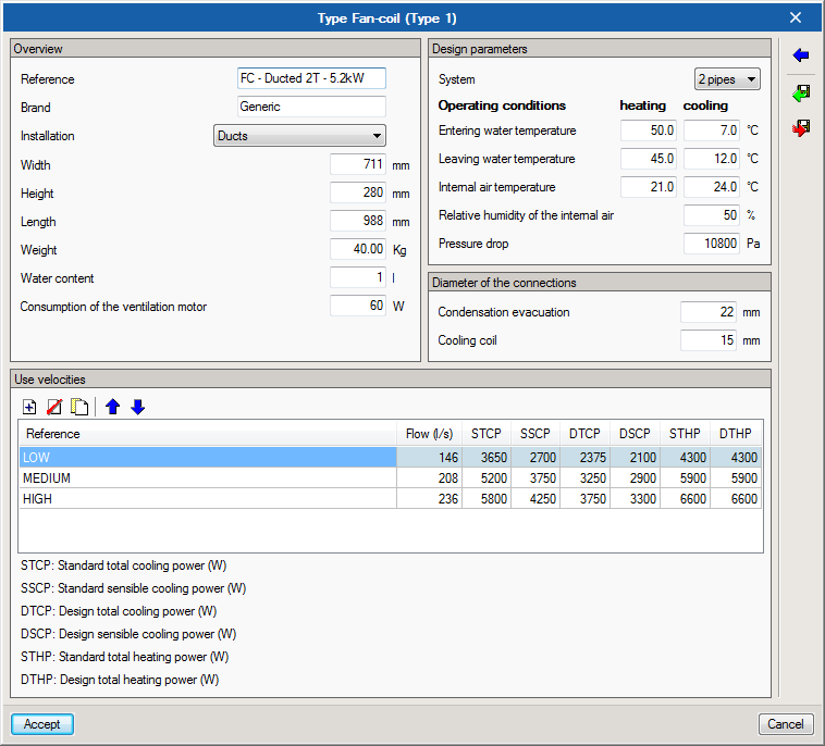
As of the 2017.c version, and as occurs with other elements, each fan coil that is incorporated in the drawing has a properties panel where users can indicate the type of fan coil, the loads to cover, the working temperatures, ventilation flow, etc. The program calculates the corrected load depending on the ventilation air conditions, and checks if the selected fan coil model has enough power to cover these loads.

The fan coil library, which is available in the General settings of the program, displays the nominal power of each model, air flow of the ventilator, etc.

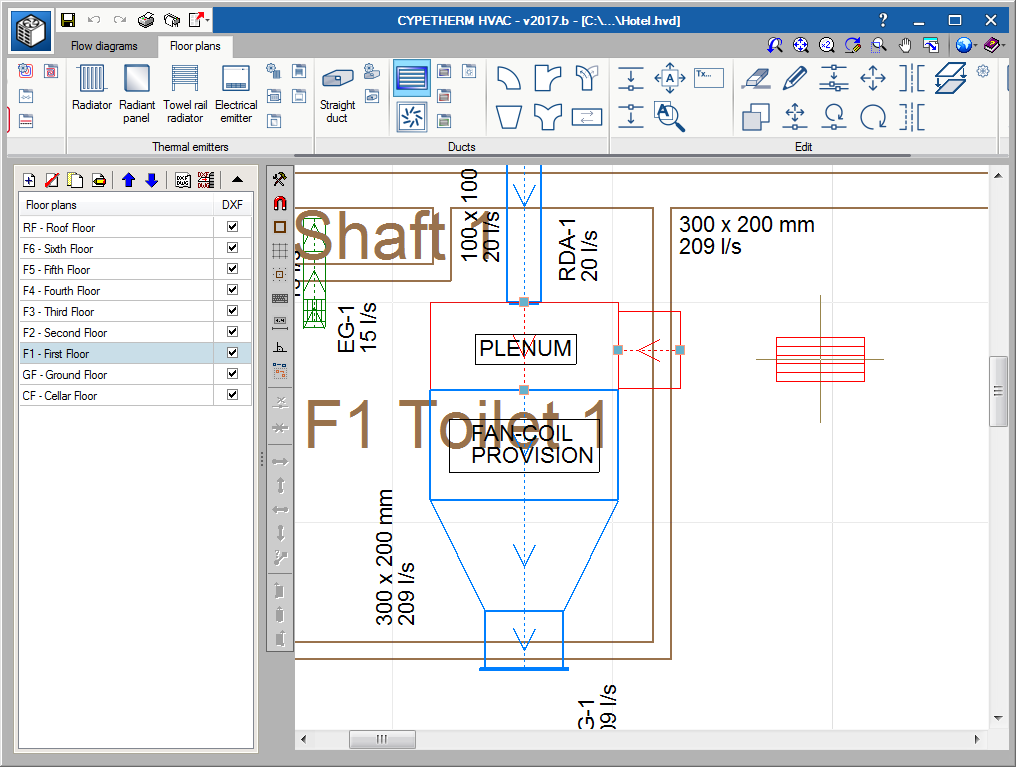
Positioning of grilles in ducts

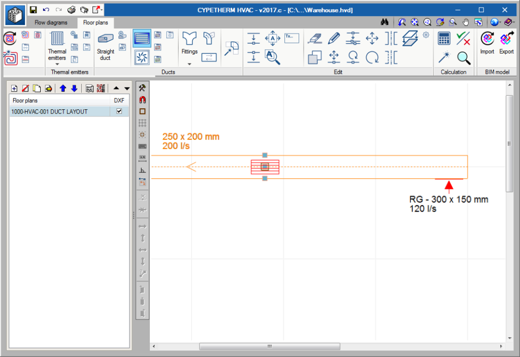
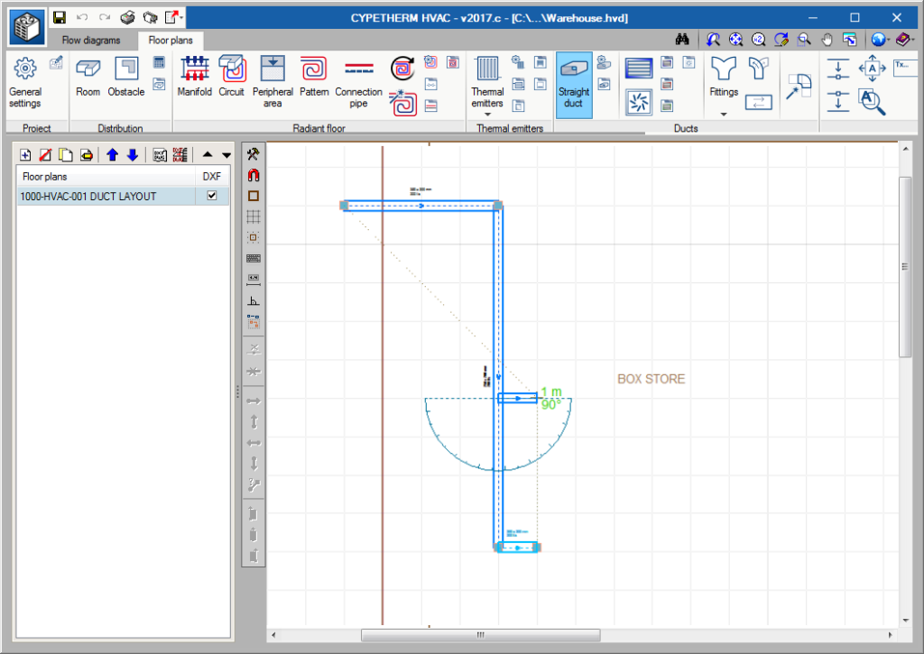
In previous versions, a grille was introduced by pressing the mouse button at the position where it was to be placed in the duct.

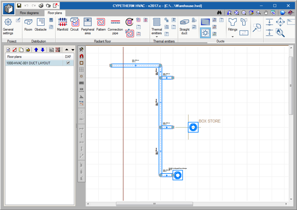
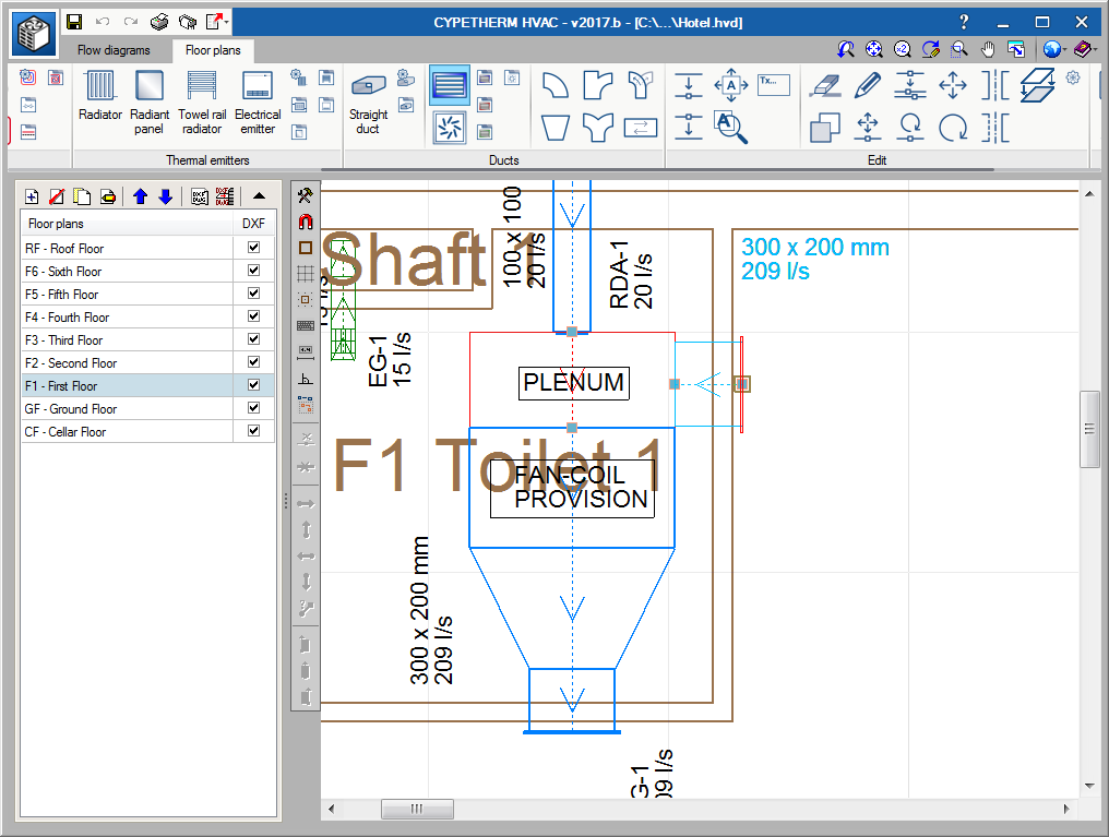
As of the 2017.c version, the position of a grille in a duct requires to clicks of the mouse button. The first click marks the position of the grille along the duct and the second defines whether it is to be placed vertically or horizontally. To define which of the three positions will be that adopted by the grille (horizontal, vertical, to one side or the other of the duct), before pressing the mouse button for the second time, users can move the mouse cursor to one side, the middle or the other side of the selected duct. An image appears on screen, upon moving the cursor, indicating which will be the position of the grille if the mouse is clicked on for a second time.

Automatic generation of duct connections

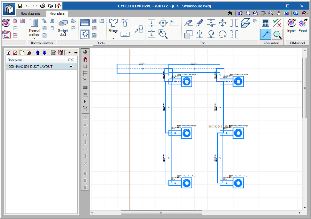
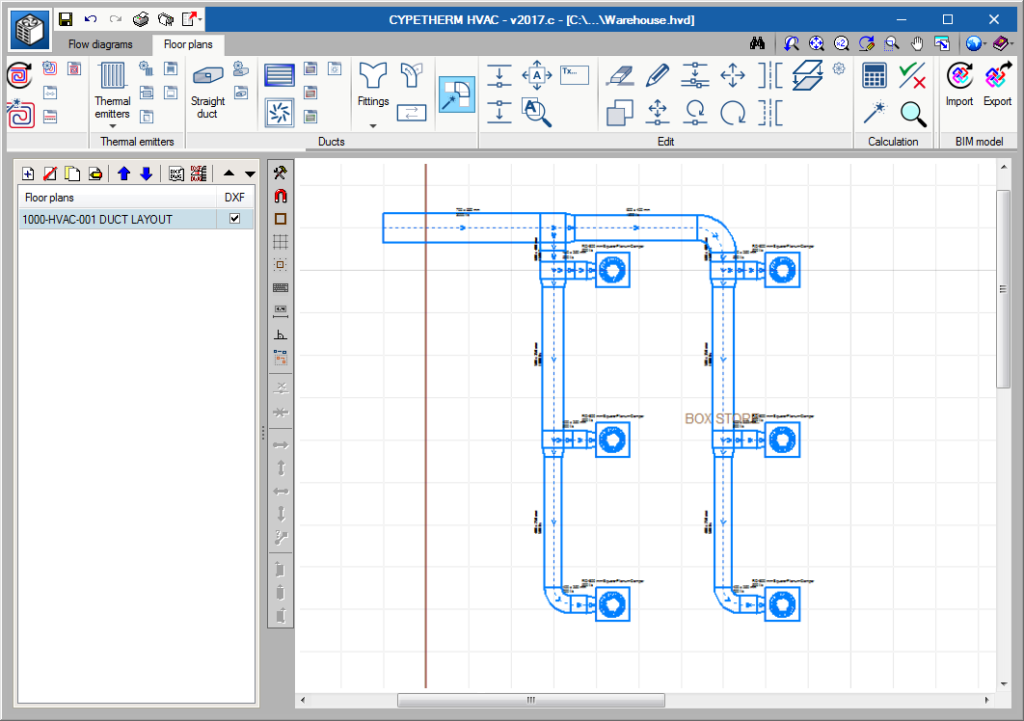
As of the 2017.c version, CYPETHERM HVAC automatically generates all the connection elements of the network: elbows, transitions and branches.

Therefore, as of this version, the introduction and design procedure of a network is as follows:

  • Introduce ducts
  • Introduce grilles or diffusers
  • Design ducts
  • Automatically generate connections

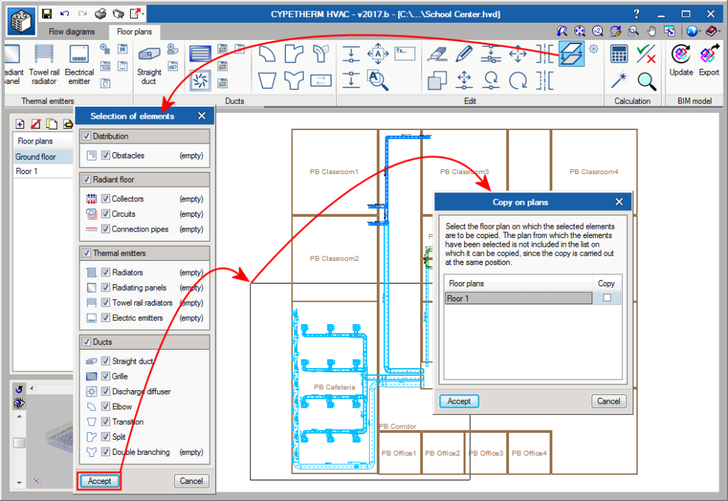
Copy on another floor plan

Using the “Copy on another floor plan” button, users can select elements of the installation to then copy them to another floor.

Vertical grilles

Grilles placed by users at duct ends are automatically placed in a vertical position.