This new tool allows content to be copied between the same type of tags. The content includes the variables of the tag.

Create tag based on an existing tag
This new tool allows users to create the same type of tag with the same content as the tag selected on the sheet. To do this, once the tool has been selected, users must select the tag they wish to copy and then the element to which they wish to assign the tag.

Graphical editing of the reference system of the model
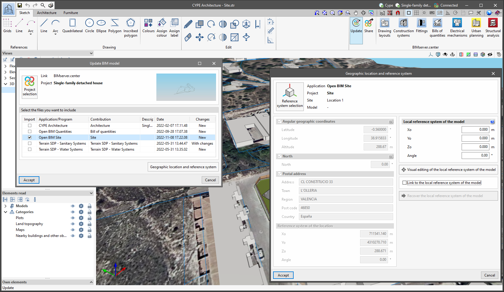
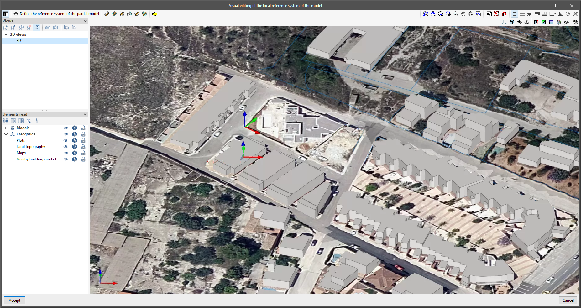
Since version 2022.a, the applications integrated within the Open BIM workflow via the BIMserver.center platform include a tool for managing project reference systems. This option is available from the configuration window that appears when linking or updating a BIMserver.center project via the "Geographic location and reference system" option. As of version 2023.d, the applications now allow users to run a graphical environment where they can visually define a reference system for their model. To do this, the "Geographic location and reference system" window now contains the "Visual editing of the local reference system of the model" option.
From the "Visual editing of the local reference system of the model" window, the origin and orientation of the reference system of the model can be indicated in the workspace with the "Define the reference system of the partial model" tool. Both the axes of the reference system of the model, which we have just entered and the axes of the reference system of the site can be viewed in the workspace. The latter appears with a "Site" tag.
To make it easier to define the reference system, the 3D models corresponding to the BIMserver.center project contributions selected during the linking process are displayed. The management of the visibility and object snaps of these models is carried out from the "Elements read" menu in the left sidebar of the window. The "Views" menu can also be found in the same options bar, from which different types of 2D and 3D views of the model can be generated. These tools can already be found in several CYPE applications. For more information on how they work, please refer to the User’s Manual for the 3D work environment tools available in CYPE applications.
Apart from 3D models, 2D drawings or plans can also be imported from CAD files (".dxf", ".dwg", ".dwf") or images (".jpeg", ".jpg", ".bmp", ".png", ".wmf", ".emf", ".pcx"). These files and object snaps are managed through the "DXF-DWG Template" and "Template object snaps" options accordingly.
Once the editing is complete, the coordinates and orientation of the reference system of the model with respect to the reference system of the site are moved to the corresponding fields in the "Geographic location and reference system" window.
Pinned menu bars
Options that used to display submenus in previous versions now feature a pinned toolbar.

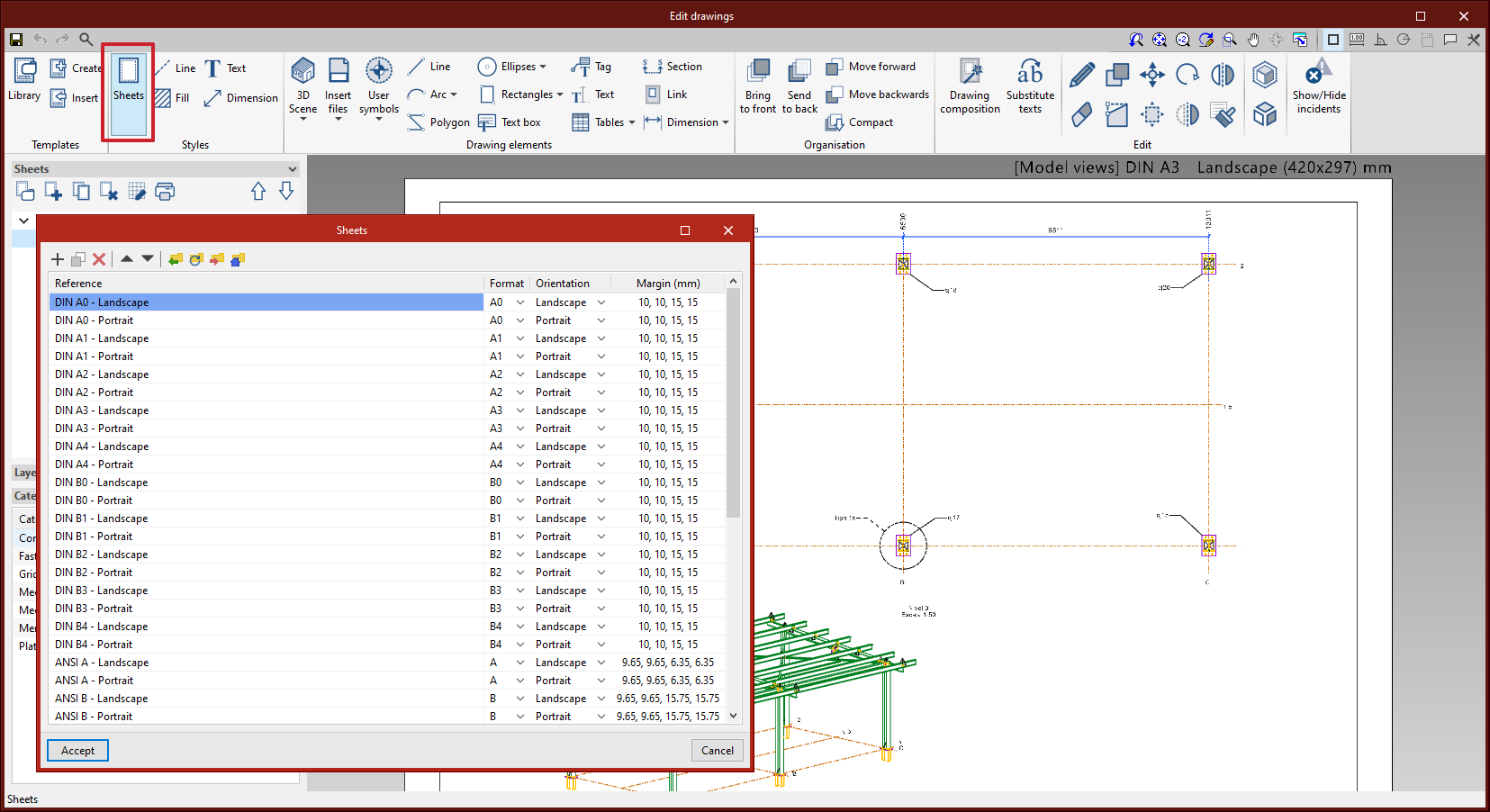
Sheet style
The editing of sheet styles has been added. From "Styles" > "Sheets" you can control the orientation and margins of each sheet format.
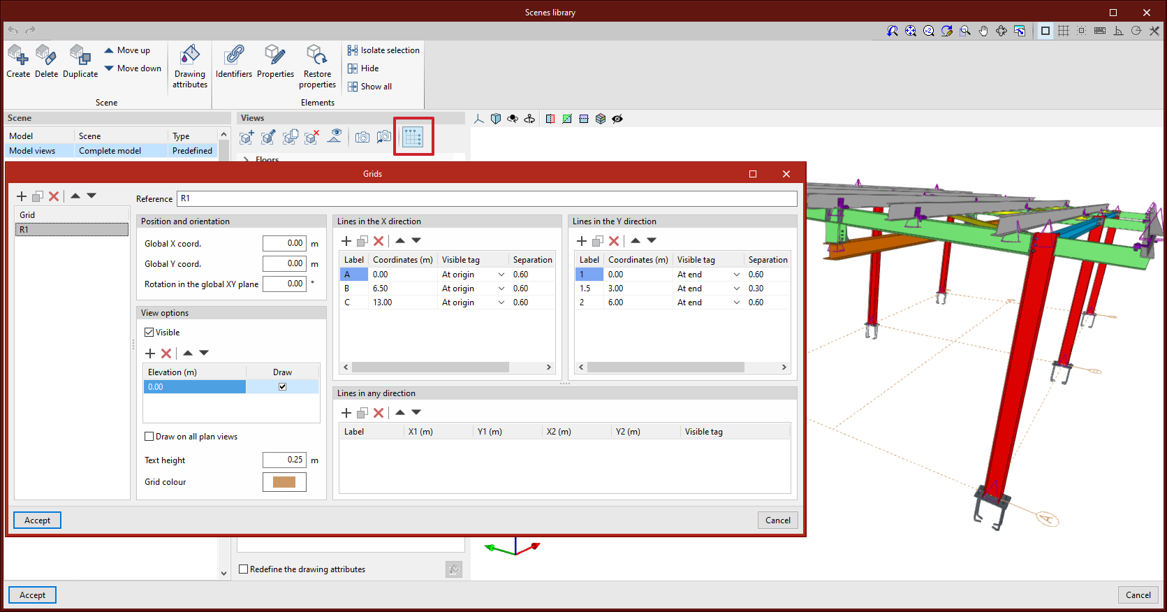
Grid editing by scene view
As of version 2023.d, scene views can include grids. These grids can be edited from the scenes library. In StruBIM Steel, scenes in model views will automatically include the grid if it has been defined in the model.
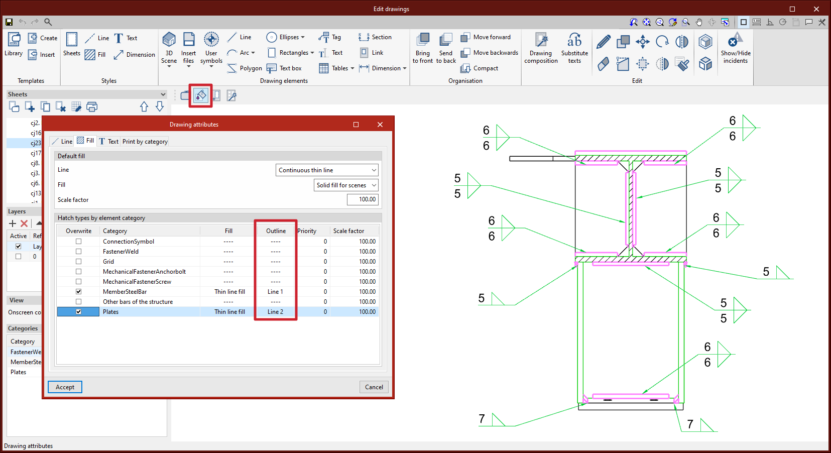
Editing the line style for the outline of section fills in scene views
In version 2023.d, the editing of the line style for the outline of section fills in scene views has been added. From "3D Scene" > "Drawing attributes" > "Fill", users can access the dialogue box that allows them to edit the line style by category.
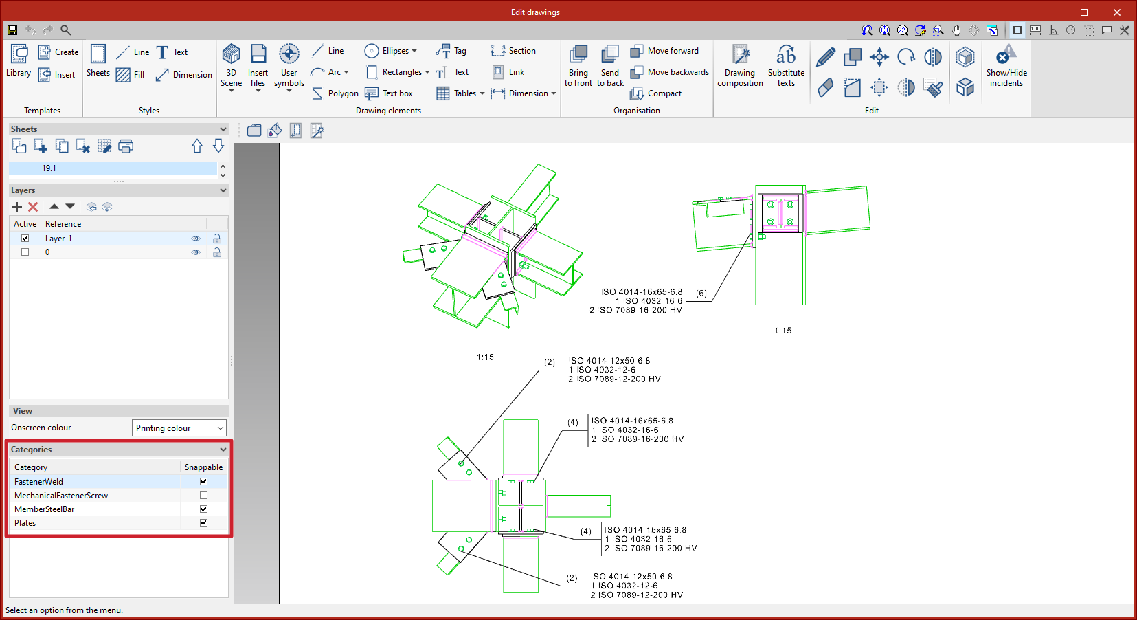
Management of categories that can be snapped from the sidebar
In version 2023.d, the management of categories marked as "Snappable" has been added to the sidebar. Each element in the 3D scenes belongs to a category.
This improvement is useful, for example, when tagging or dimensioning items to deactivate categories that don't need to be snapped. The sidebar location allows quick access to this commonly used tool.
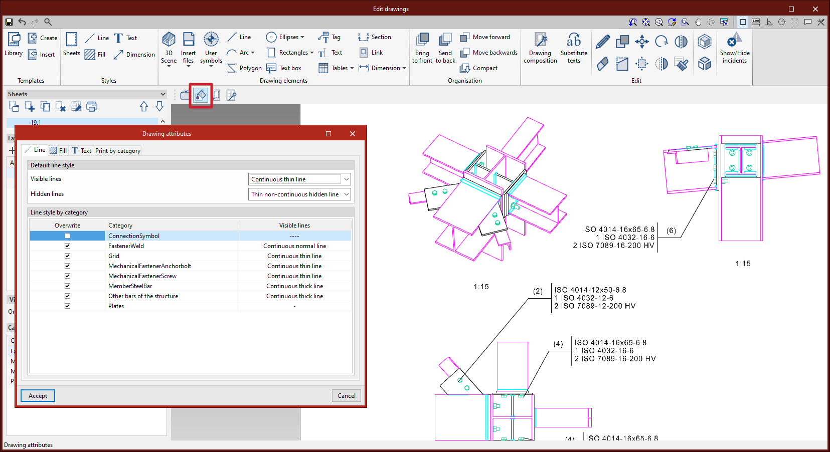
Print management by categories of elements
In version 2023.d, the print management of elements according to their category has been added. From "3D Scene" > "Drawing attributes", users can access the dialogue box that allows them to select the categories to be printed ("Print by category" tab). Unchecked categories will be displayed on screen but will not be printed. This implementation is particularly relevant, for example, with connection symbols, which should be displayed on screen so they can be tagged, but not printed (see new feature "Connection symbols in drawing layouts").

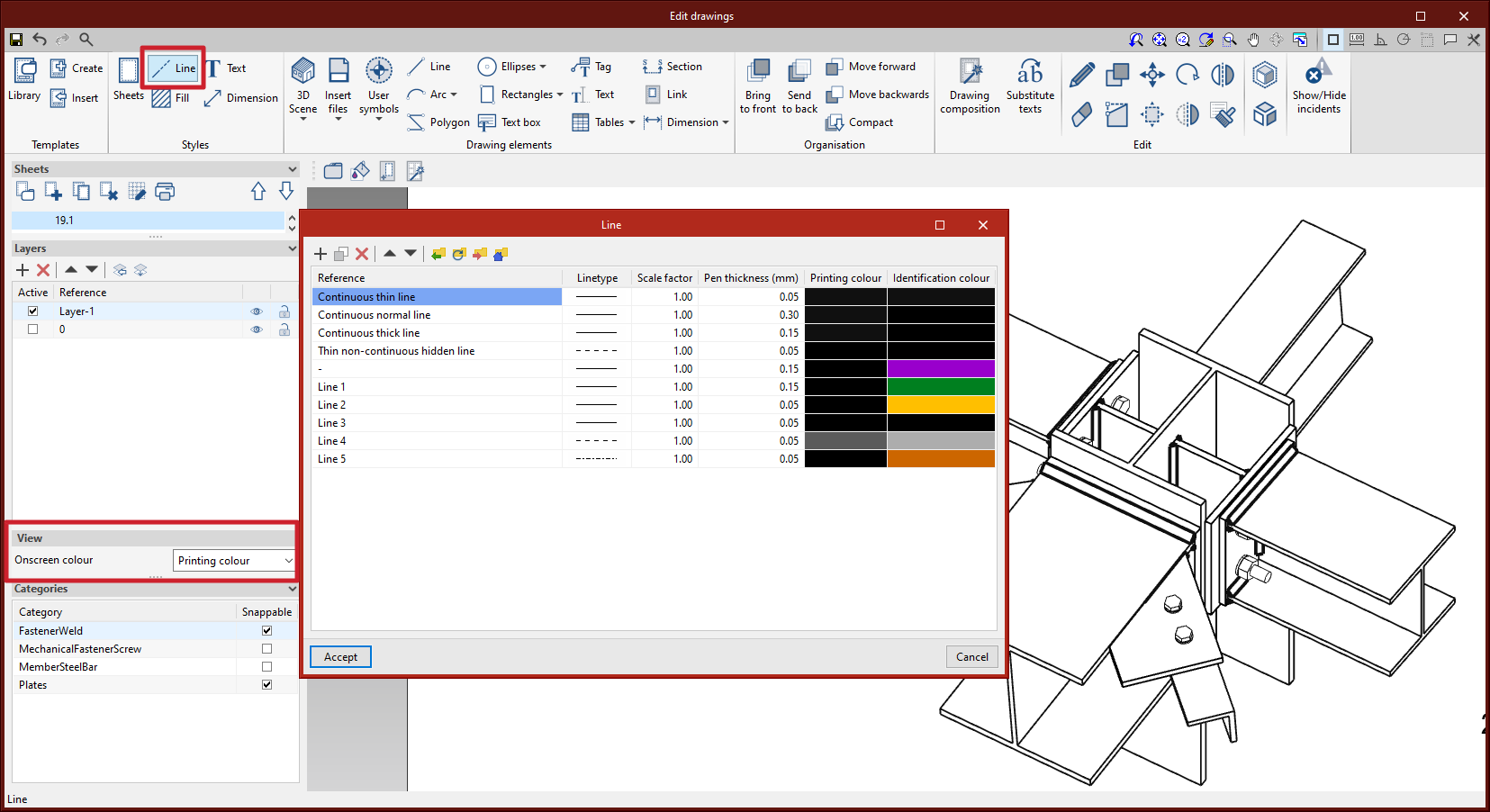
Line type editing for vector image scenes
Line style editing by category has been added. The dialogue box for editing the line style can be accessed from the "3D Scene" tool > "Drawing attributes" option. When the scenes are defined as a vector image, the edges of the elements can be seen on screen according to the line style and the colour chosen by the user between the identification colour or the printing colour.