As of the 2017.e version, users can open and analyse several StruBIM Analysis projects simultaneously.

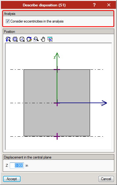
When the layout of shells is defined, users can choose whether or not to consider the eccentricity of the shell during the analysis of the forces.
Users can define factors that modify the stiffness of shells. Using these factors, the axial, bending and shear stiffness can be modified, for the local axes of the shell.

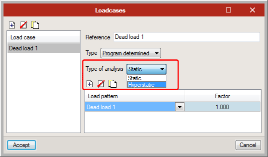
As of the 2017.e version, a new attribute has been added to loadcases: the “Type of analysis”.
Users can select between a static analysis or hyperstatic analysis. In previous versions, a static analysis was carried out for each loadcase. The hyperstatic analysis is required when structures are designed with post-tensioned slabs. Even though users can choose to carry out a hyperstatic analysis for any loadcase, this type of analysis is logical when there is equilibrium amongst loads that are introduced, as occurs with post-tensioned cases, since the supports of the structure are eliminated.
As of the 2016.k version the view of the BIM model and management of BIM links are implemented in the program. More information on this new feature can be found in the “Open BIM workflow in StruBIM programs” section of this webpage.

As of the 2016.k version the view of the BIM model and management of BIM links are incorporated in the program.
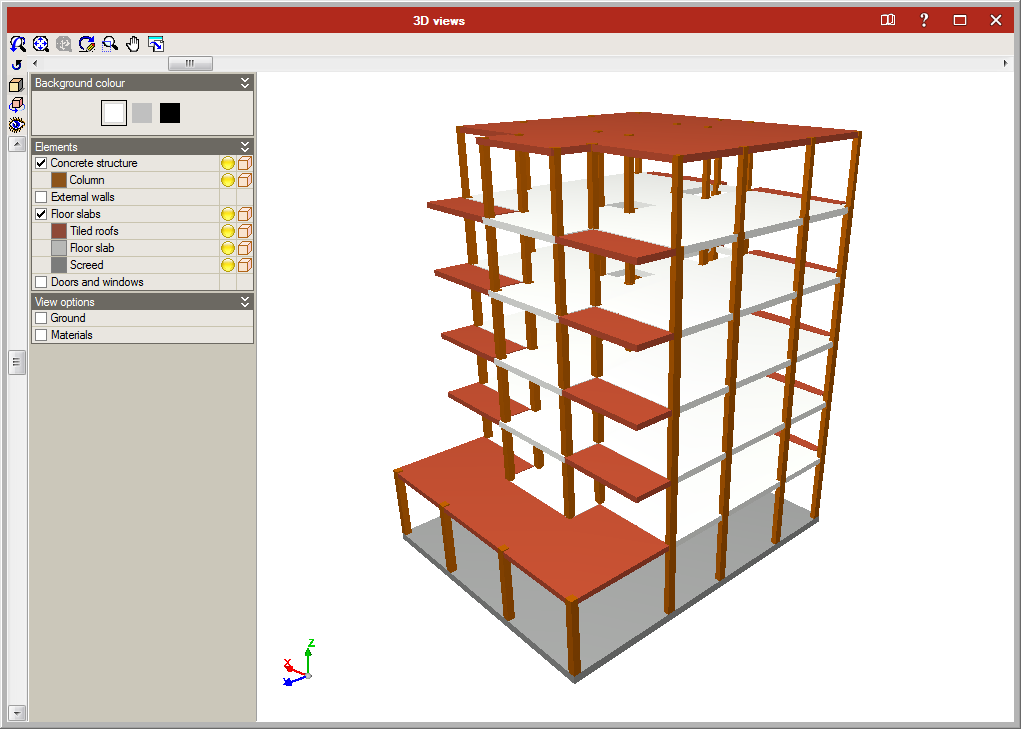
The view of the BIM model incorporates the representation of the linked IFC model or models in the view of the bar analysis model.
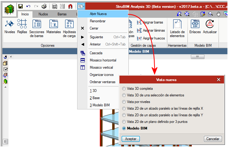
This view window is opened from the Window menu > Open new > BIM model.
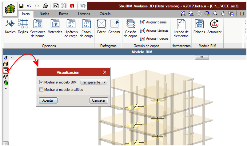
The BIM model can be represented as transparent or solid, as well as having the option to view the analysis model.
In the BIM model window, all the IFC models in the linked models list are displayed. Users can link the IFC files present in the directory containing the IFC files of the physical model with which the analysis model is imported (BIM project directory).
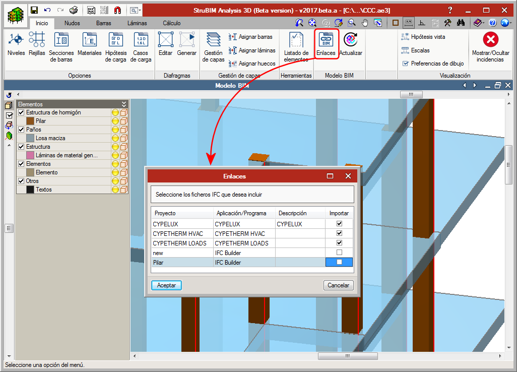
Los cambios en los ficheros IFC del directorio del proyecto BIM se reflejan en el botón de Actualizar, mostrando la advertencia para que actualicemos el modelo.

IFC BUILDER
Creation and maintenance of building IFC models. This application is integrated in the OPEN BIM workflow via the IFC4 standard.
Features:
- Graphic user interface (GUI) to introduce columns and flat slabs
- Import of DXF/DWG/JPG/BMP files
- Open BIM edges generation
- Open BIM (IFC4) modelling
StruBIM Analysis 3D
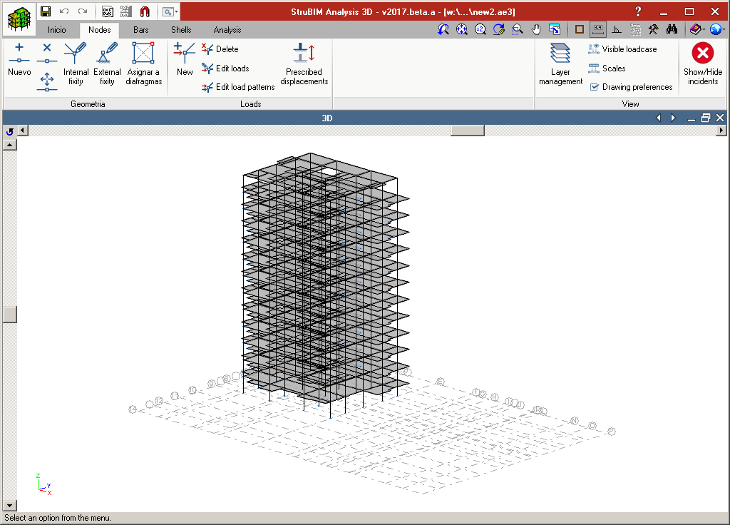
StruBIM Analysis 3D is a tool created to generate, edit and design an analysis model that has been developed based on a structural model.
The analysis of the acting loads is carried out using a 3D spatial analysis applying stiffness matrix methods.
The structural model can be imported using an IFC format file, generated using CYPE’s IFC Builder, other BIM modelling programs or an XML format file.
The analysis model is generated based on the imported structural model, and the structure is discretised into bar-type elements, nodes and shells composed of finite elements (FEM). Users can adjust the model by defining or editing:
- Loadcases
- Values of loads acting on elements.
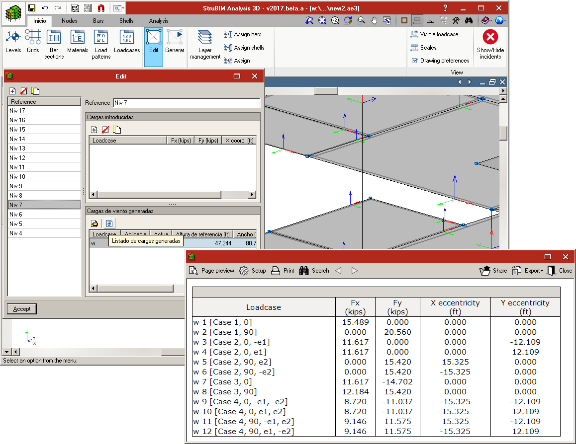
- Wind loads that are generated automatically in accordance with ASCE 7-10
- Diaphragms
- Boundary conditions
- Section and material properties
- Shell discretisation sizes
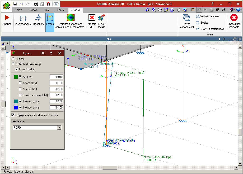
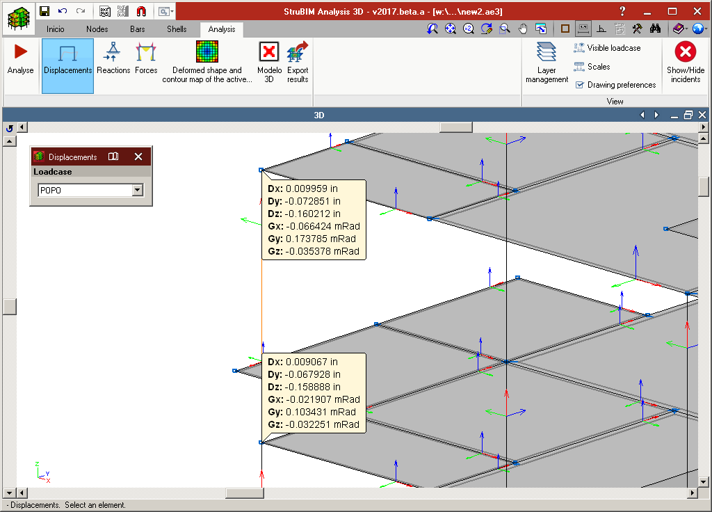
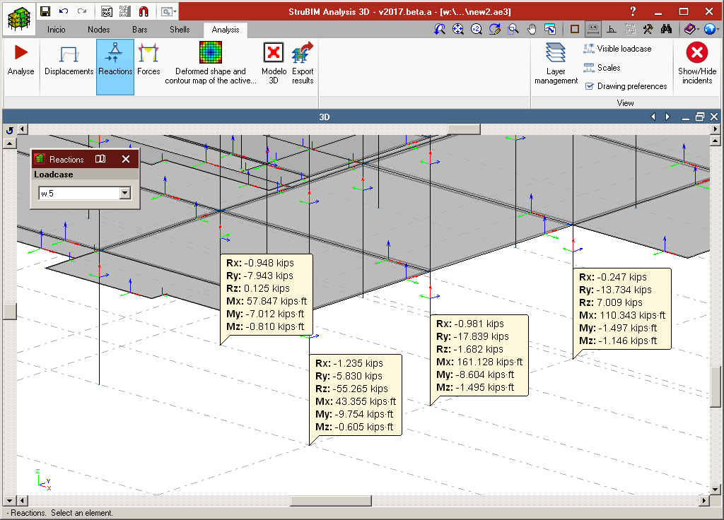
Once the analysis has been completed, users can consult:
- Displacements and reactions
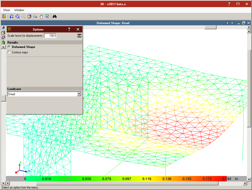
- Force and displacement diagrams
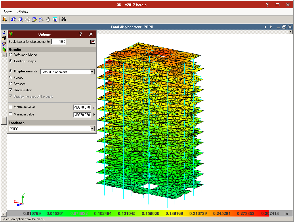
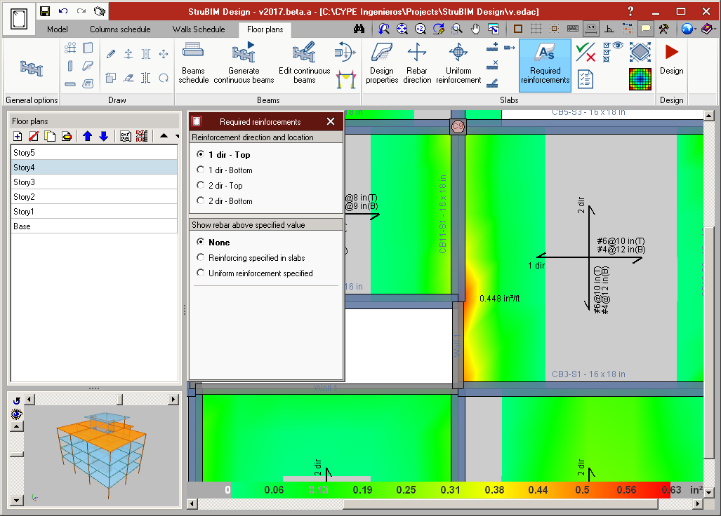
- Contour maps for forces and displacements
The analysis model and its results are exported to StruBIM Design.
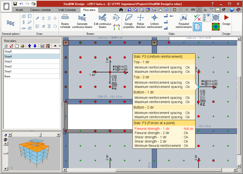
StruBIM Design
StruBIM Design is a tool which designs, checks and edits reinforced concrete and steel structural elements, based on a structural model and a calculated analysis model.
The structural model can be imported using an IFC format file that has been generated using CYPE’s IFC Builder, other BIM modelling programs or an XML format file. The calculated analysis model is imported from StruBIM Analysis 3D or from the XML file if it contains the necessary information.
StruBIM Design designs and checks structural elements (columns, beams, floor slabs and walls) and provides the technical drawings in accordance with the requirements of the project (Record Engineer).
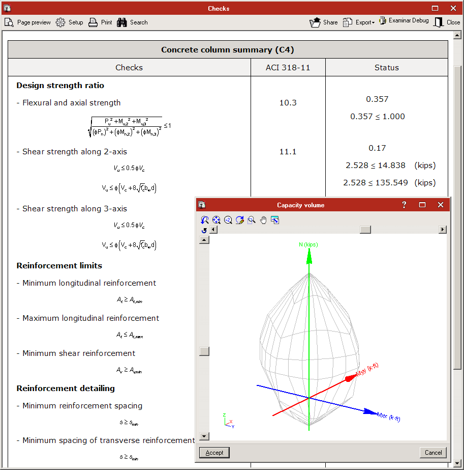
The reinforcement of the following reinforced concrete elements is designed and checked in accordance with the requirements of ACI 318-14, ACI 318-11 and ACI 318-08:
- Rectangular or circular-section columns
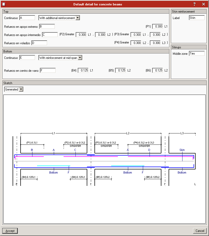
- Rectangular-section beams
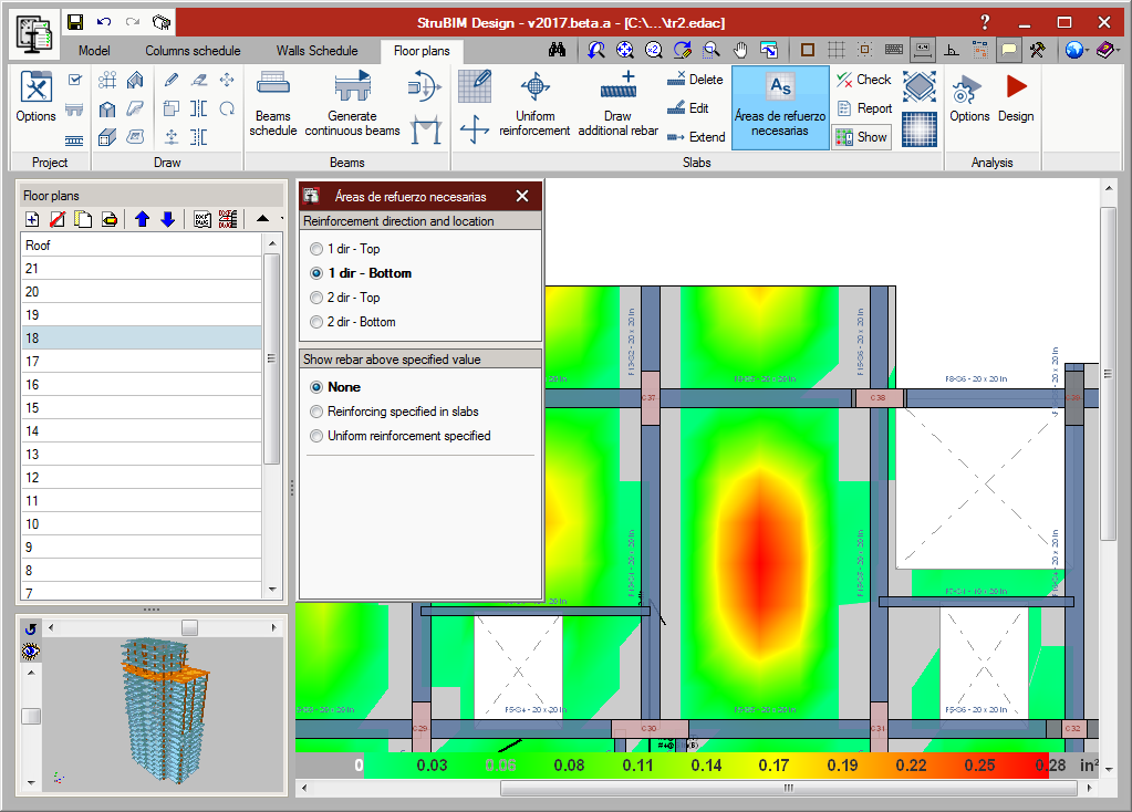
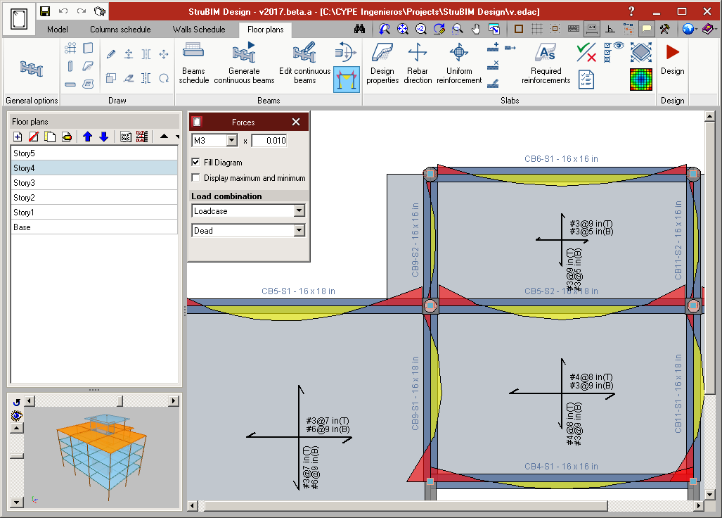
- Flat slabs
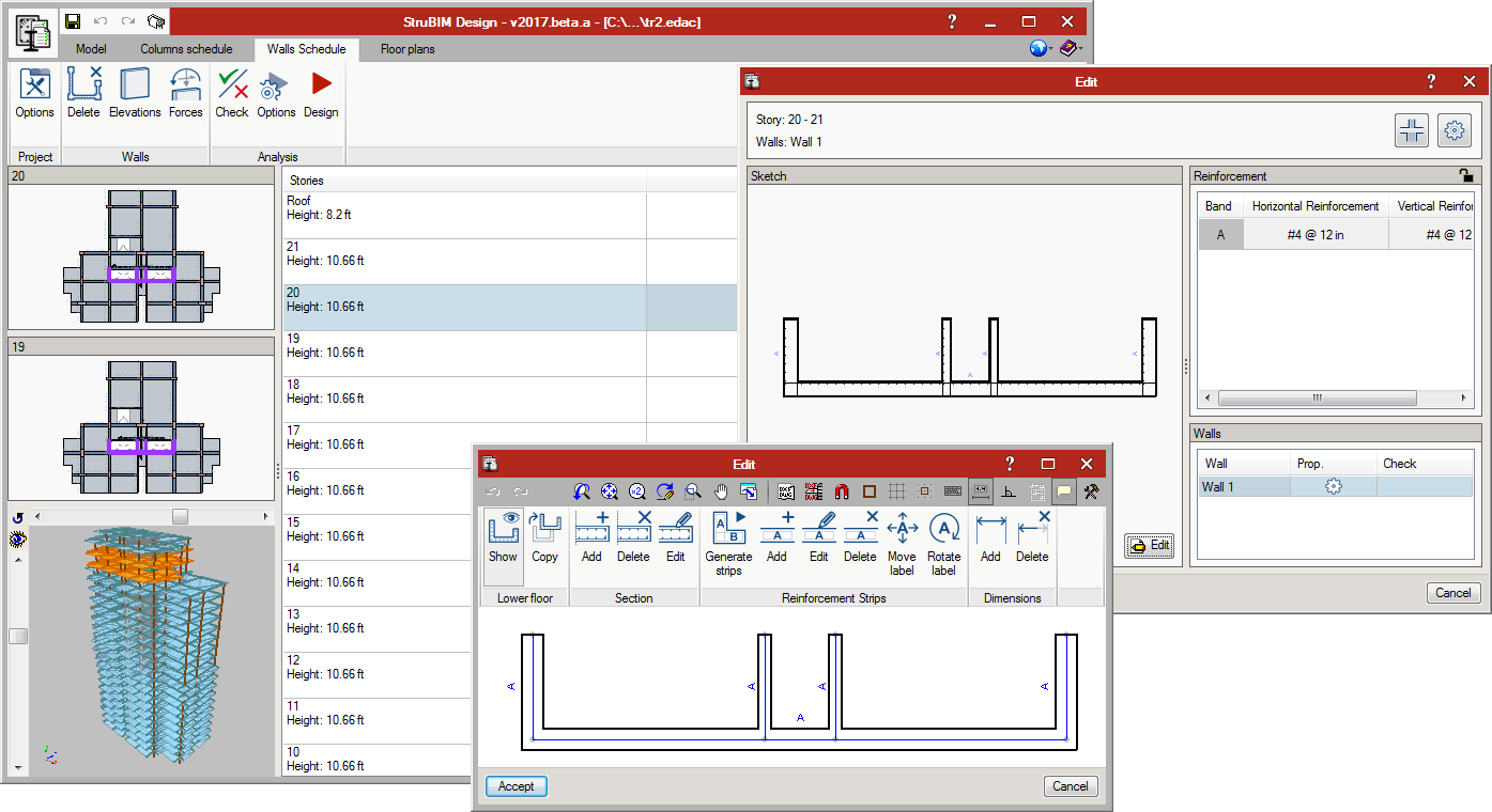
- Walls
Steel elements are designed and checked in accordance with ANSI/AISC 360-10.
Design results for reinforced concrete elements (sections and reinforcement) and steel elements (sections) can be edited, and then checked.
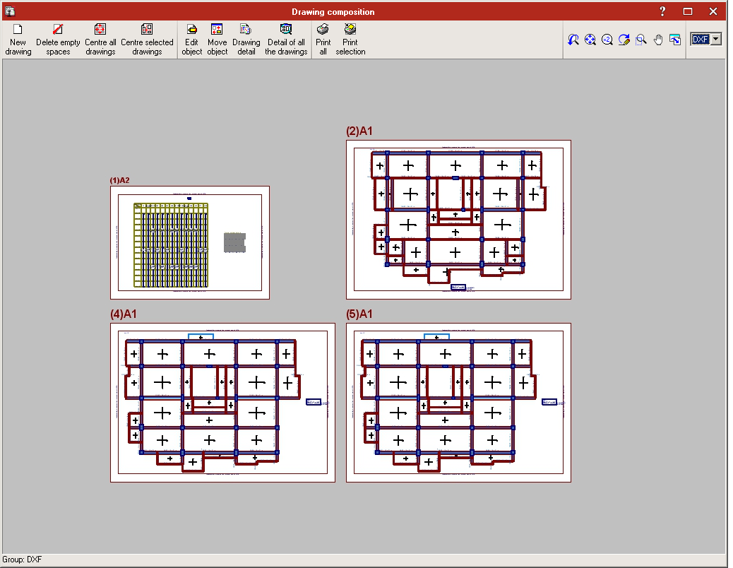
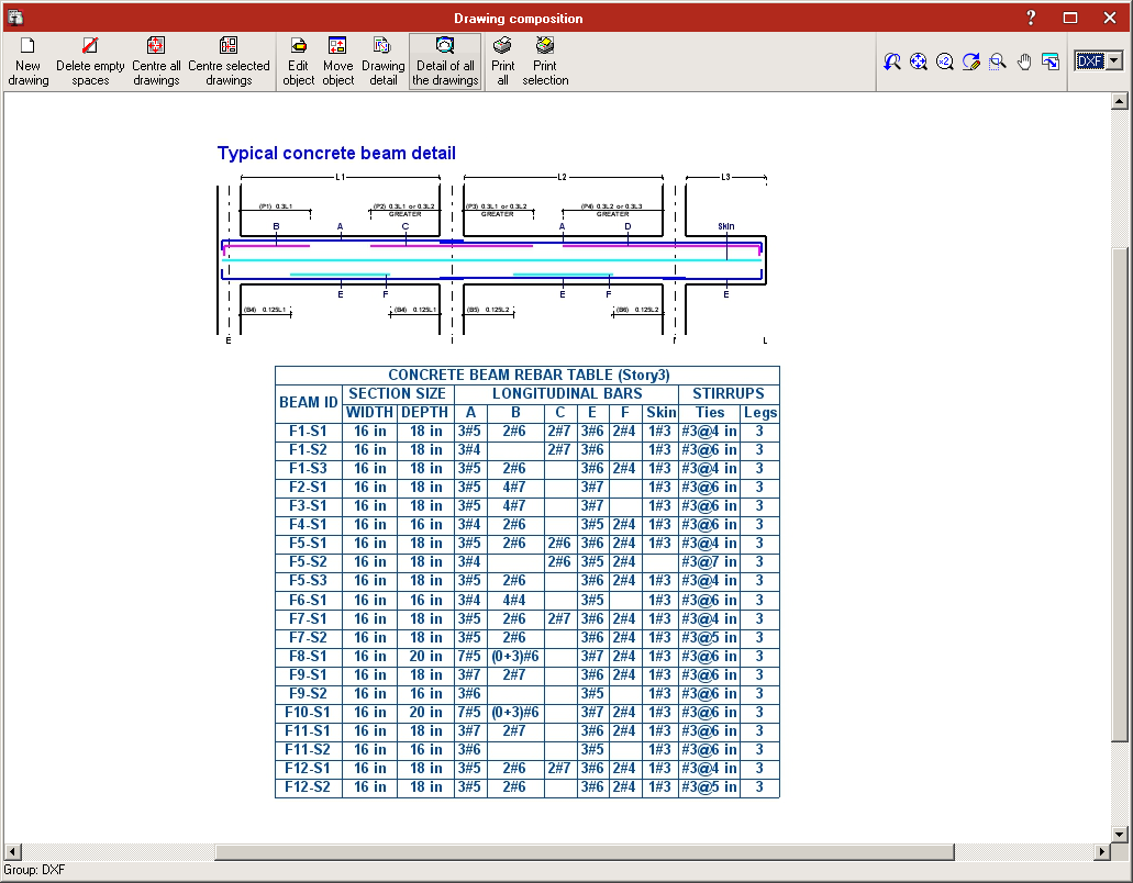
Design results can be directly transferred to technical drawings of the various elements: columns, beams, slabs and walls, in accordance with representation requirements and project contents (Record Engineer):
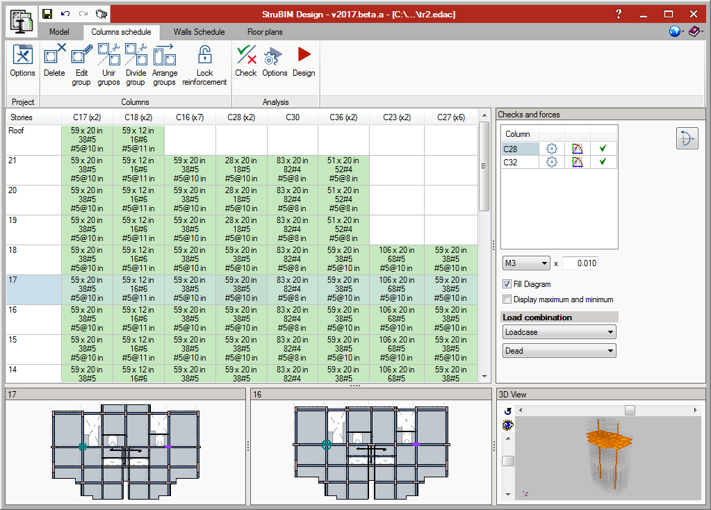
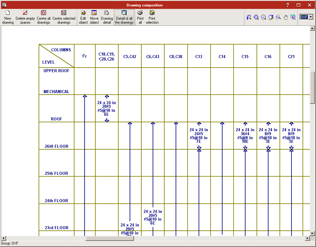
- Column schedule
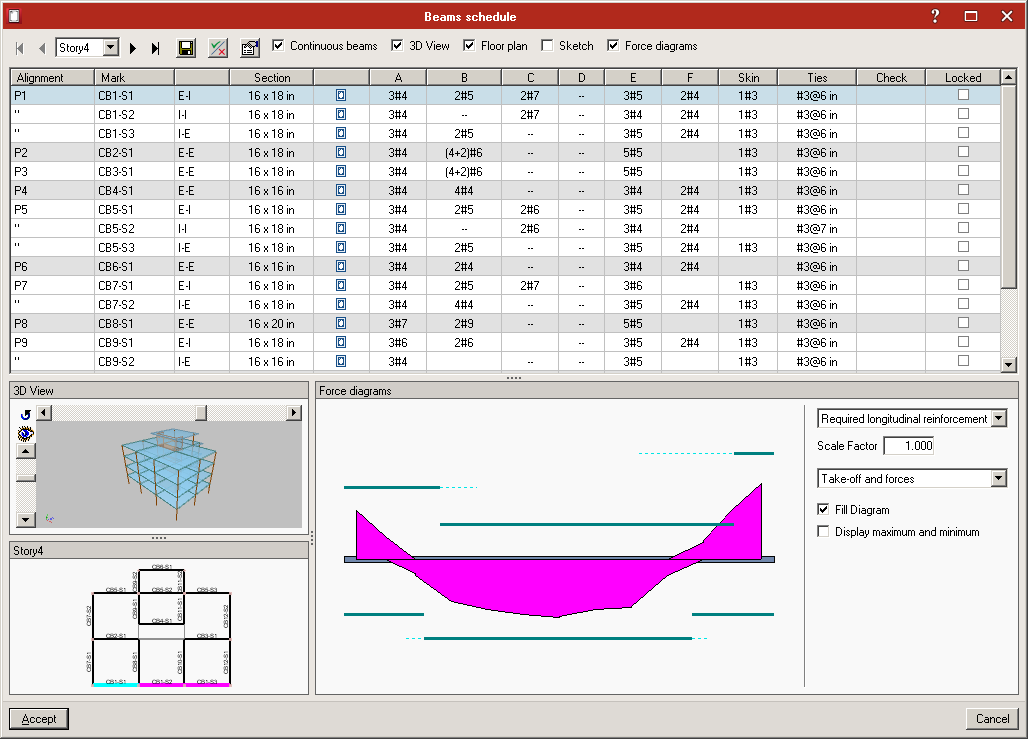
- Beam schedule
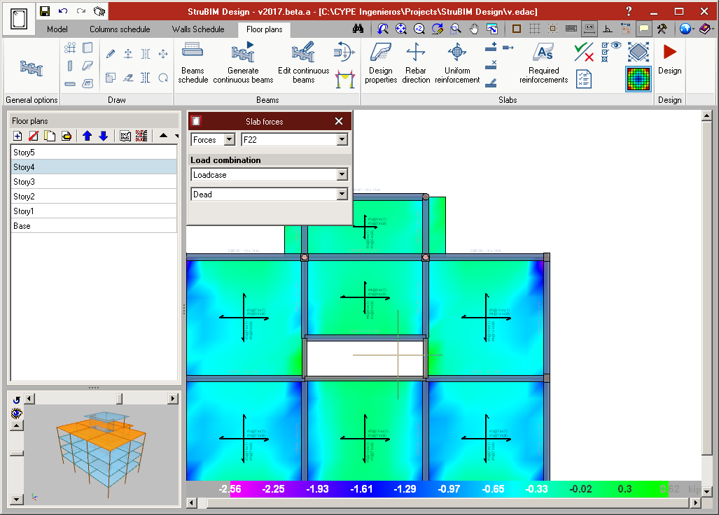
- Slab reinforcement drawings
- Wall schedule
Versions
Three program versions of StruBIM Analysis 3D and StruBIM Design are available:
- StruBIM Free
- StruBIM Pro
- StruBIM Expert