CYPE Mentor

Update history​​

StruBIM Steel

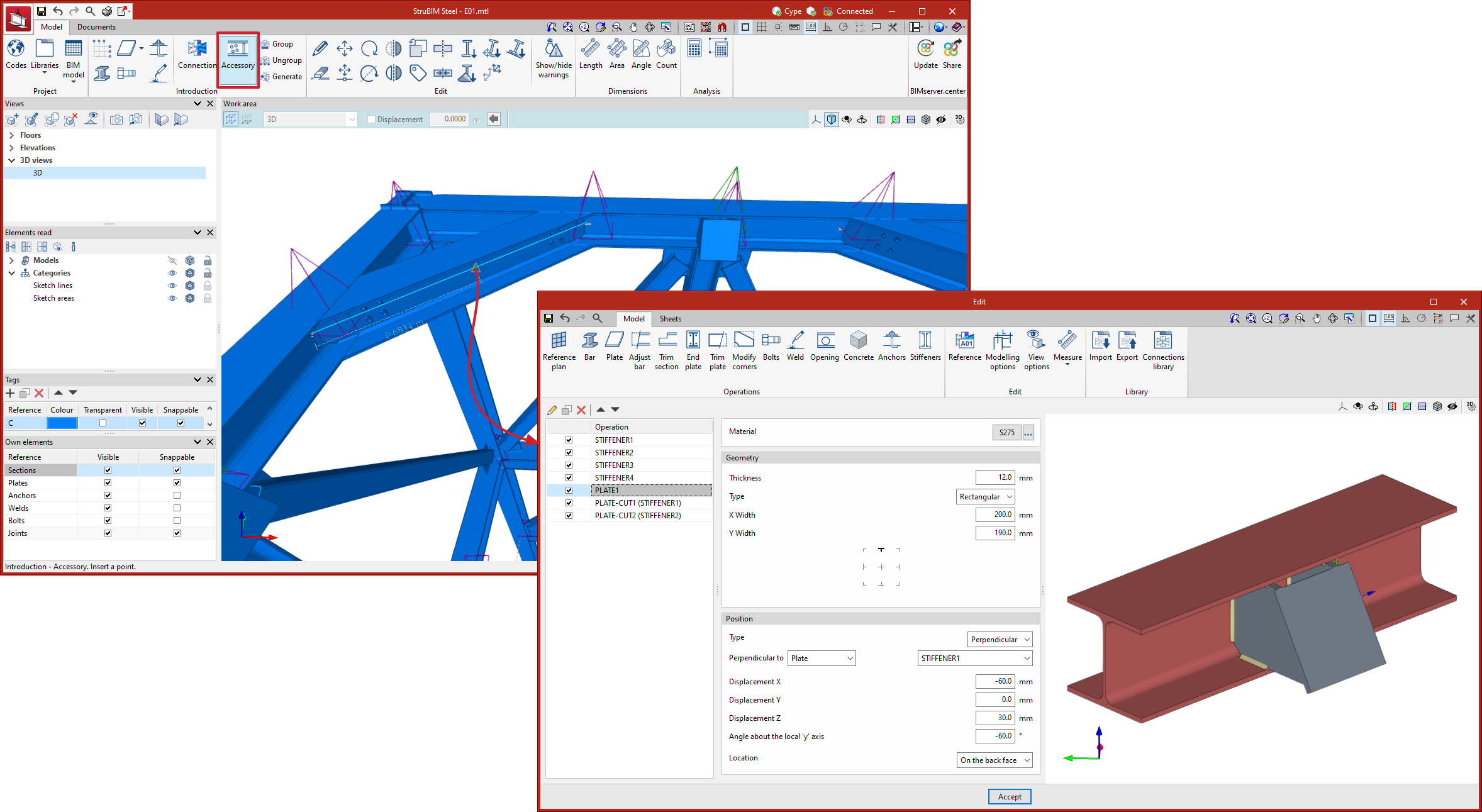
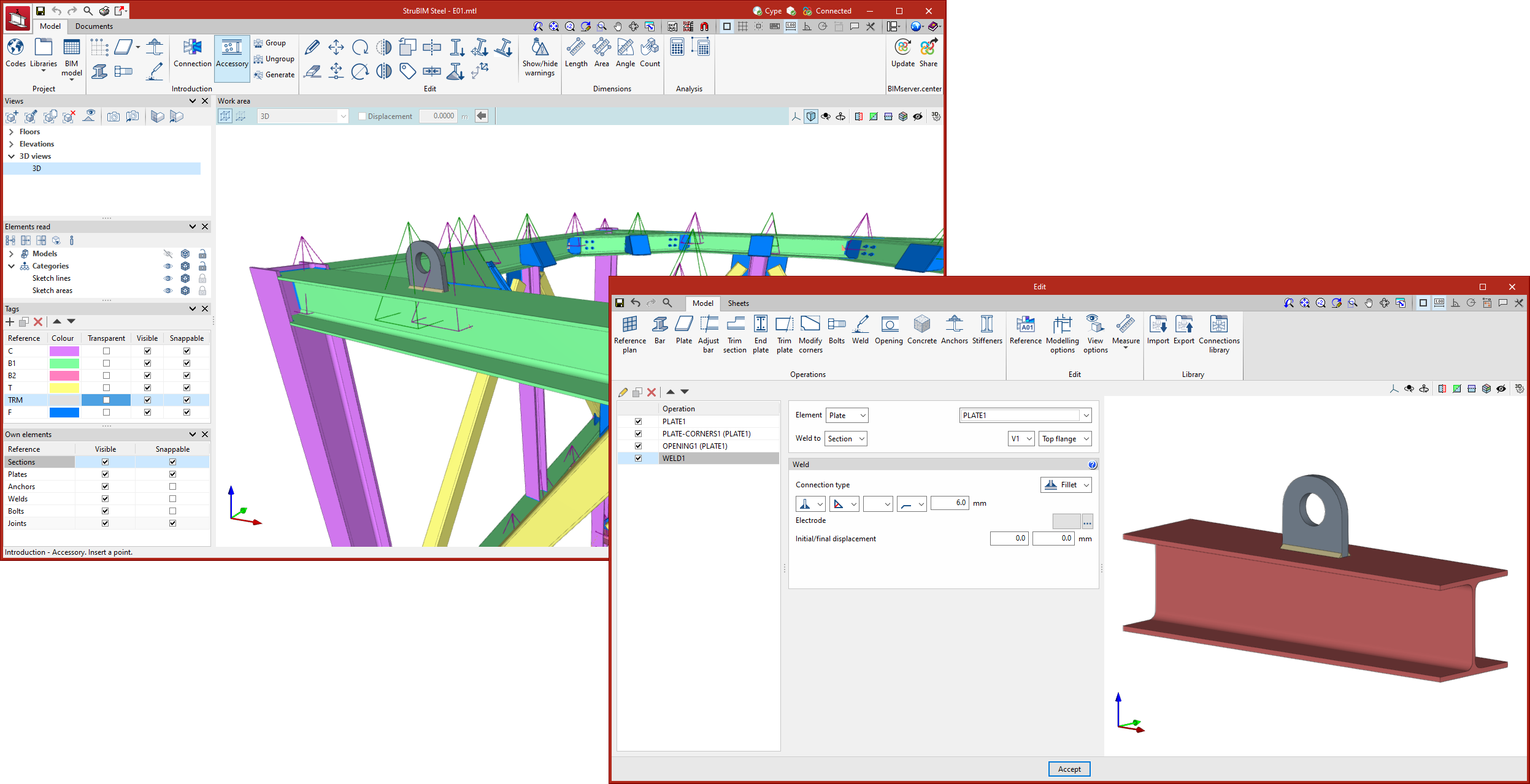
In version 2023.f, the "Accessories" tool has been implemented. This tool allows sections to be edited in order to enter elements at intermediate points. The accessories work dialogue box is similar to the CYPE Connect connection editor. The purpose of this tool is to allow users to insert holes, openings, reinforcements, lifting lugs, etc. with the advantages offered by the connection editor. Just like the connections, the accessories can also be grouped together and saved in a library.

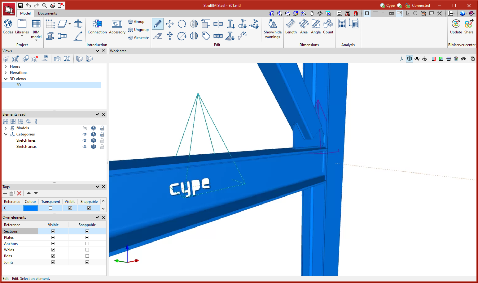
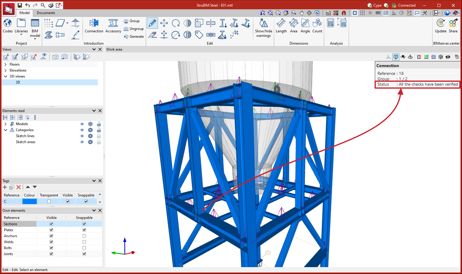
The symbol representing the accessories is a green pyramid, as opposed to the purple pyramid corresponding to the connections.

As of version 2023.f, when the model is updated, the forces of the connections will be updated automatically. In previous versions, the bars of the model were updated but the forces were updated for each connection when the user clicked on "Generate from the BIM model".

"Automatic saving options" have been added to the "Configuration" menu. Using these options, users can configure when the job will be saved automatically.

As of version 2023.f, information text windows of the connections will include the status.

As of version 2023.f, information text panels will include the weight of the selected part or assembly.

As of version 2023.f, the list of tags includes the new "Transparent" column. Elements will be shown as transparent when their tag is marked as "Transparent".

Two new tools have been implemented to carry out operations with symmetry:

  • Symmetry (copy)
    Copies a selection of elements with symmetry with respect to a vertical plane defined by two points.
  • Symmetry (move)
    Moves a selection of elements with symmetry with respect to a vertical plane defined by two points.

A new tool, "Invert the direction of the X axis" can be found in the "Edit" menu. Using this tool allows users to reverse the direction of the X-axis of a selection of sections.

A new tool, "Align section to plane" can be found in the "Edit" menu. This tool allows users to align a selection of sections to a plane. For example, this could be useful when placing the purlins of a roof in line with the top face of the main beams.

After selecting the sections to be aligned, right-click the mouse and select the plane from the faces of the sections and plates in the model.

A new tool, "Assign insertion point" can be found in the "Edit" menu. This tool allows you to assign the levelling point, rotation angle and Y and Z displacements in local axes to a selection of sections.

A new tool, "Assign material", can be found in the "Edit" menu. This tool allows the type of material to be assigned to a selection of sections.

Quantities reports of the elements of the structure have been implemented. The following tables are included in the implemented reports:

  • Assembly quantities
  • Assembly and part quantities
  • Sections quantities
  • Summary by type of section
  • Plate quantities
  • Bolt quantities
  • Weld quantities
  • Anchor quantities

These reports can be generated for the whole structure, for a selection of assemblies, or for a selection of parts.