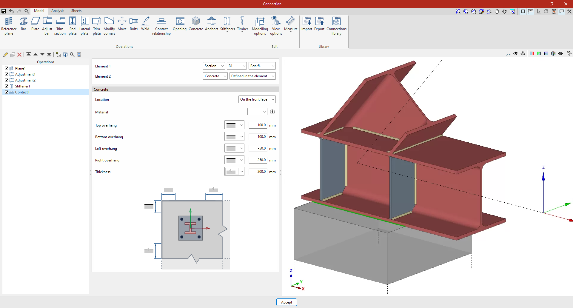
In version 2025.b the new "Contact relationship" operation has been implemented. This operation defines contact relationships between steel surfaces or between steel surfaces and concrete elements.
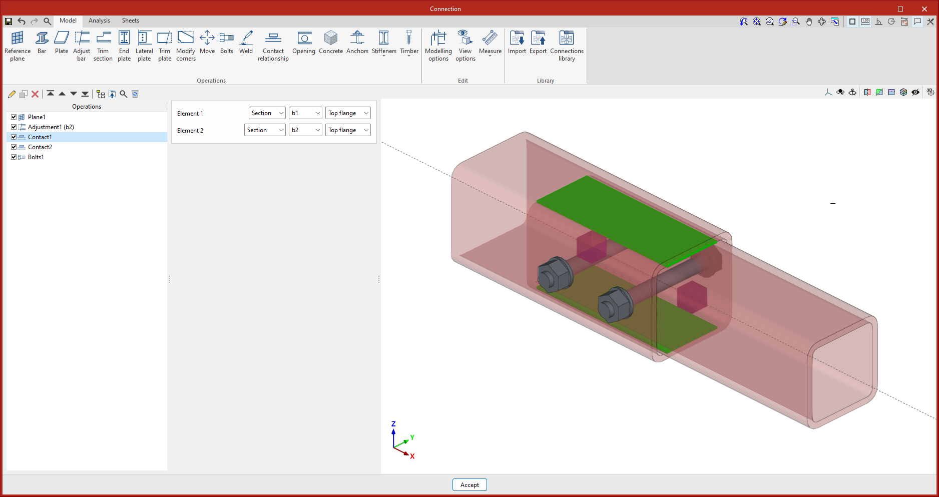
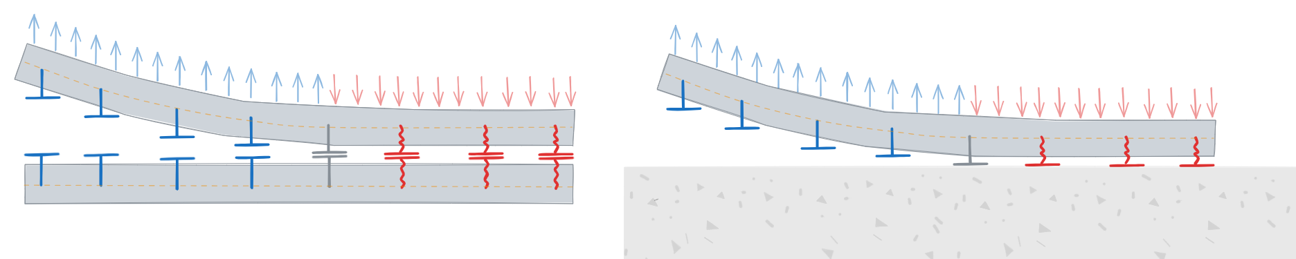
When bolting plates together, the program already establishes these contact relationships automatically, as when anchoring a plate to a concrete element. This new operation can also be carried out without the need to add bolts or anchors. In the design model, non-linear relationships are established between the nodes of the mesh of the plates, which only work in compression.
This operation is represented in the 3D view by a green surface between the elements selected in the operation. When selecting contact between a plate and a concrete element, users will be allowed to select an existing concrete element or a new element defined in this operation.