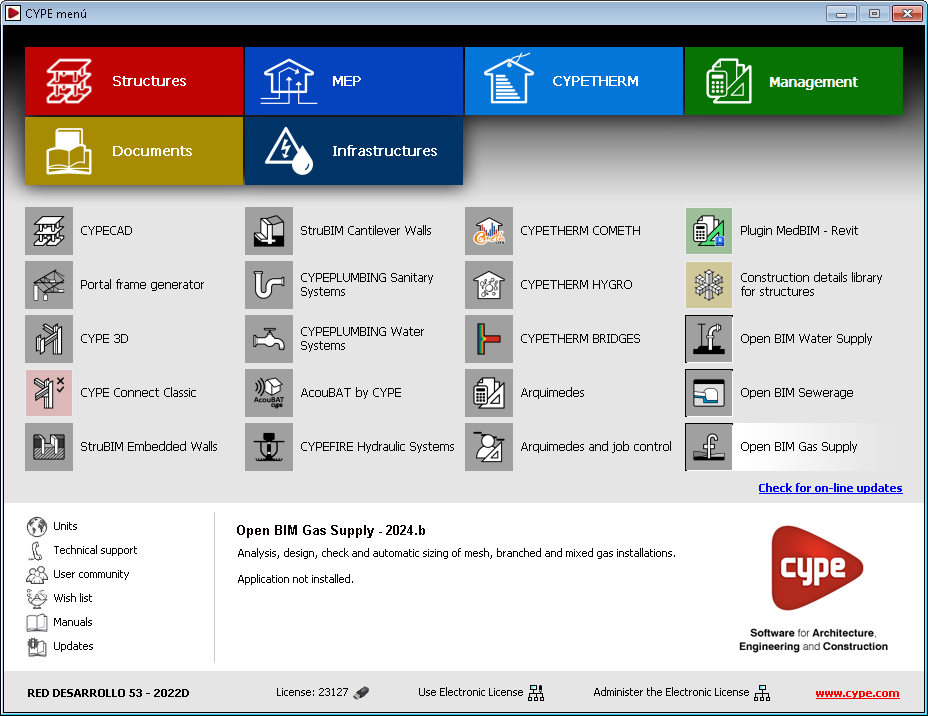
Classic menu of CYPE programs
As of version 2024.b, the classic menu of CYPE programs has a downloadable version available from the BIMserver.center platform Store.
This new classic menu downloaded from BIMserver.center includes the same applications and layout as the version available from the download area of the CYPE website, but with some differences.
When installing the BIMserver.center menu, only those applications that are not available for individual download in BIMserver.center will be included in the installation. The other applications in the BIMserver.center menu (those that can be downloaded individually from the BIMserver.center Store) can be downloaded and installed when they are opened for the first time from this new menu.
Long access paths
In previous versions, file paths used by applications were limited to a maximum length of 256 characters. This restriction is not specific to CYPE tools but is set by default in the Windows file system. As of version 2024.b, CYPE applications can bypass the restriction and allow the use of an extended path length for a maximum total path length of 10,000 characters. This eliminates the problems caused by the default limit and allows users to work with long access paths.
This improvement is particularly useful when working on projects with a complex directory structure or with long file names. By allowing longer paths, CYPE applications offer greater flexibility in file organisation.
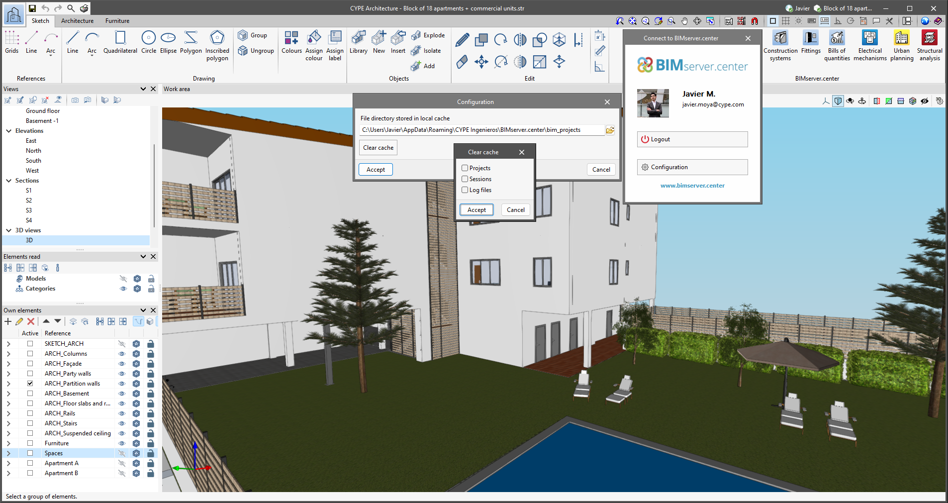
Clear cache
The "Clear cache" button has been added to the CYPE applications included in the Open BIM workflow in the "Configuration" dialogue box that opens with the following sequence of commands: Select any of the options in the "BIMserver.center" tool group > "Configuration" option in the dialogue box that appears. When clicking on "Clear cache", the following options are displayed:
- Projects
Deletes projects, contributions and documents downloaded from the platform that are in the "File directory stored in local cache". - Sessions
Deletes the data of any active sessions. This action will require applications to be re-authorised to access BIMserver.center. - Log files
Deletes transaction logging from applications with BIMserver.center.
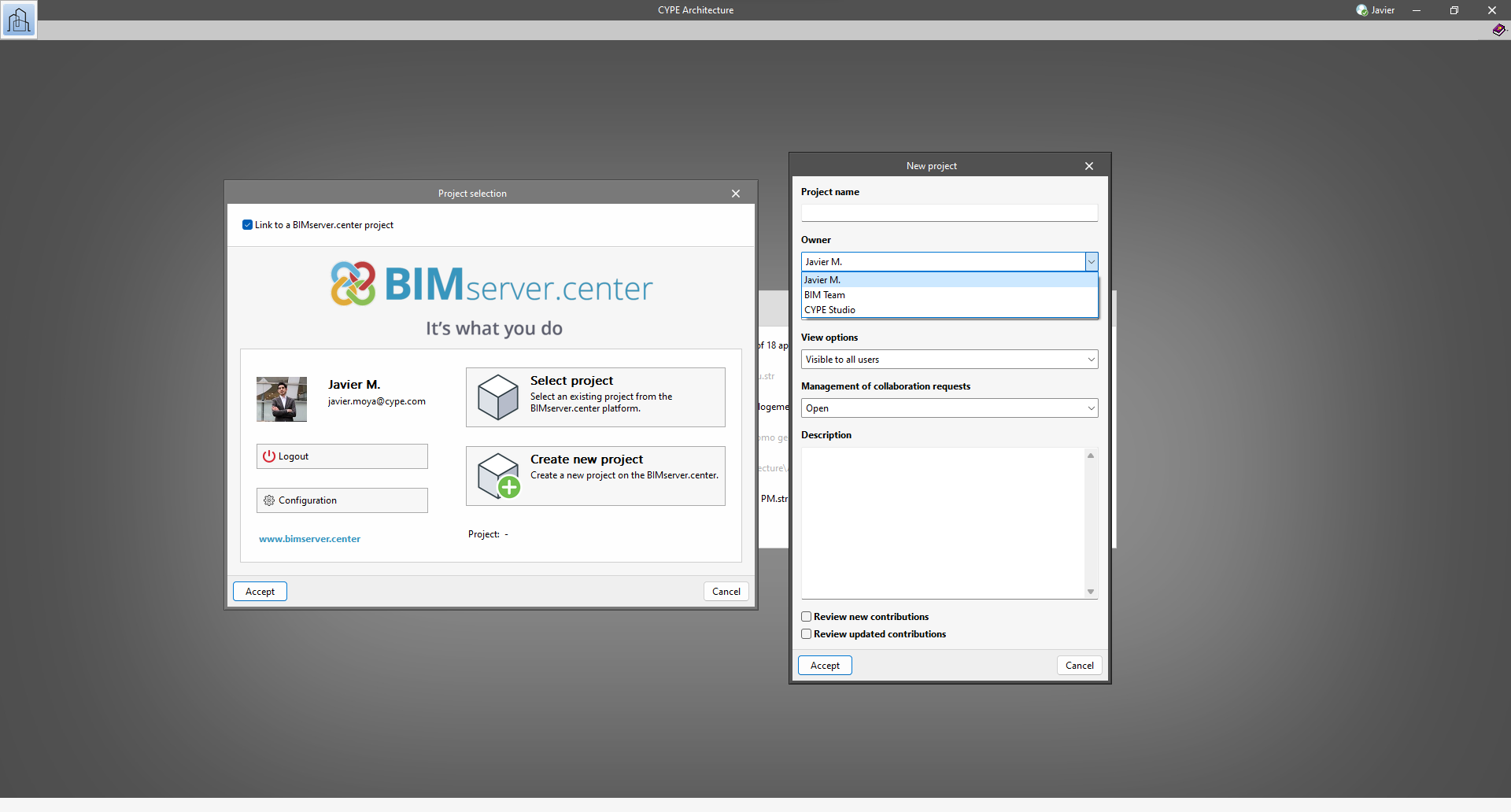
Creating BIMserver.center Corporate projects
As of version 2024.b, users can create projects associated with a "BIMserver.center Corporate" account from all CYPE applications included in the Open BIM workflow. To do this, the "Owner" field has been added to the window for creating a new project. This is a drop-down menu that includes, as one of the available options, the logged-in BIMserver.center user name along with the "BIMserver.center Corporate" accounts to which it has access. When selecting the user name as the owner, the project will be associated with this personal account, as was the case in previous versions. On the other hand, if a BIMserver.center Corporate account is selected, the project will be associated with that account.
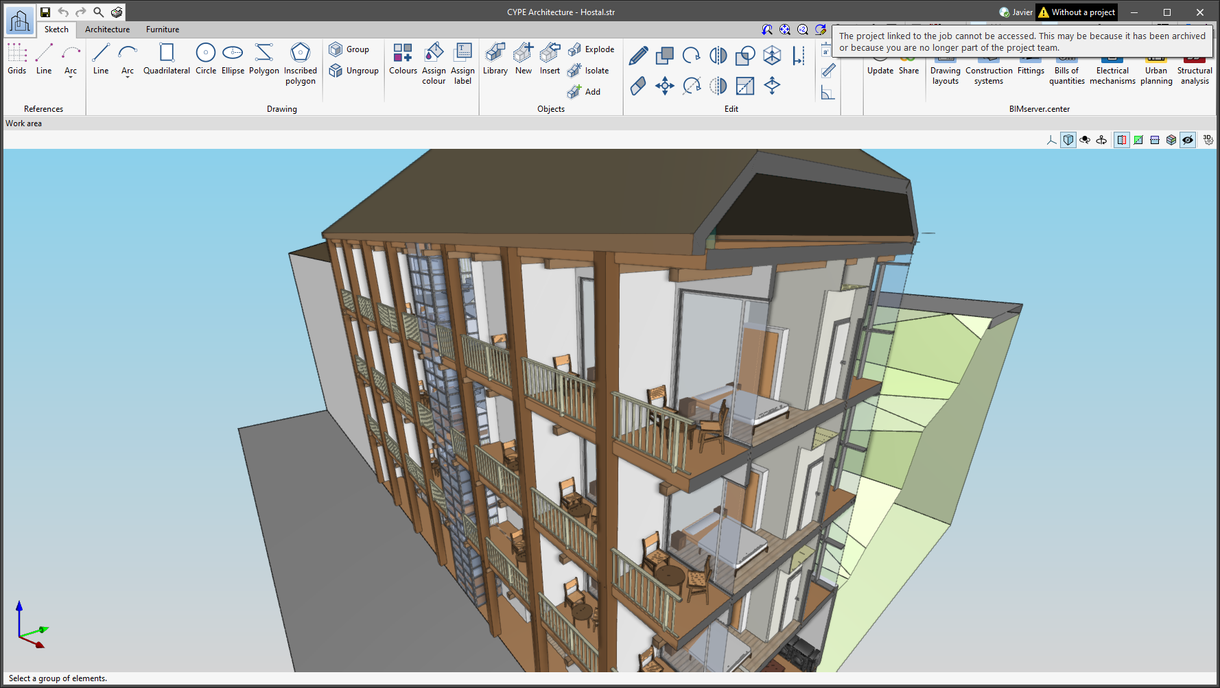
Notifications on the project status
The status information bar of the BIMserver.center project is located at the top right of the window of the programs included in the Open BIM workflow. This bar has been available in the applications since version 2022.e and shows a warning icon when there is a problem with the connection to the project, as well as other things. Now, in version 2024.b, users can obtain more information about the warning by hovering the mouse cursor over the icon.
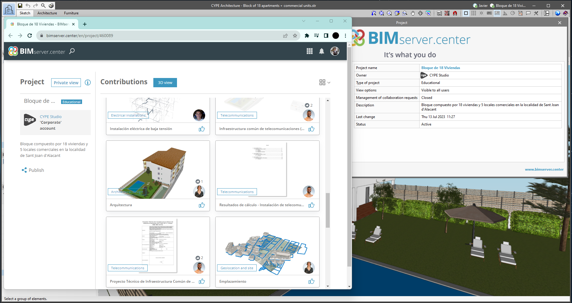
Links to the BIMserver.center platform
From the BIMserver.center project information window (displayed by clicking on the project name shown in the project information bar - upper right part of the application window) you can access the project page of the BIMserver.center platform via a link that has been inserted in the text indicating the project name.
Likewise, from the information window about the project contributions ("Contributions" option in the project information window), users can access the page of each contribution in the BIMserver.center platform. These links are inserted in the texts indicating the name of each contribution.
Improvements in the connection to BIMserver.center
Version 2024.b includes the following improvements and corrections to the connection of applications to the BIMserver.center platform:
- After sharing a contribution, there is a delay before it becomes available in the BIMserver.center project. This could result in another application not having immediate access, even if the export was made from the same computer. Now applications can read contributions from the "File directory stored in local cache" before they are accessible in BIMserver.center.
- It is now possible to export a contribution without an internet connection. When this occurs, a confirmation dialogue box will appear to inform users that if the contribution is exported, it cannot be shared in the BIMserver.center project. The contribution can be read in another application as long as it is on the same computer and linked to the same project. However, for the contribution to be available on the platform, users will need to "Share" it again with an internet connection.
- The uploading process has been improved to allow larger files to be included.
- An error that did not allow users to connect to the platform when the "AppData" system folder was not accessible has been fixed.
- An error that showed the user as logged in when the session had already expired has been fixed.
- The warning messages displayed when there is a problem in the communication with BIMserver.center have been improved.
- Now, when creating a new project, the same default fields are used as in the BIMserver.center website.
Moving elements with the arrow keys
As of version 2024.b, applications with the "Element selection tool" (this tool was implemented in version 2021.e) have the ability to move the selected model components with the arrow keys on the keyboard. The elements shall be moved on the work plane of the active view in the direction of the arrow key. Whenever the arrow is pressed, the distance that is displaced is constant, so zooming will make it larger or smaller.
Applications available in Romanian
As of version 2024.b, the following applications are also available in Romanian:
- CYPE Architecture
- Open BIM Analytical Model
- Open BIM Model Checker
- Open BIM Layout
- Open BIM Site
- Plugin Open BIM - Revit
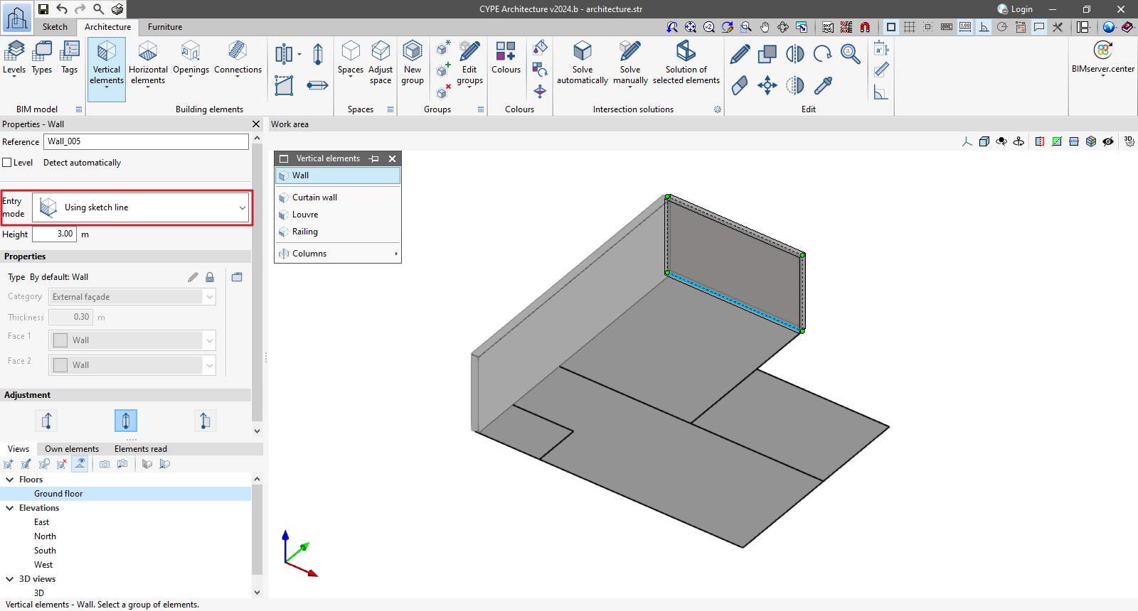
Entering walls, curtain walls and louvres by sketch line
A new entry mode has been implemented for walls, curtain walls and louvres, allowing sketch lines to be selected as baselines.
It also allows users to select multiple sketch lines, speeding up the process of entering these elements.
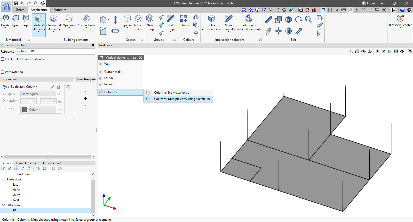
Improved column entry
As of version 2024.b, columns can be entered using two methods:
- Columns: Individual entry
Allows users to enter columns in the job one at a time by point or by sketch line. Entering with this method allows the columns to be rotated from an axis where the rotation of the column will be specified. This rotation is maintained for entering successive columns. - Columns: Multiple entry using sketch line
Allows users to enter several columns at the same time using sketch lines. This can be done with rotation by selecting the rotation angle by means of two points.
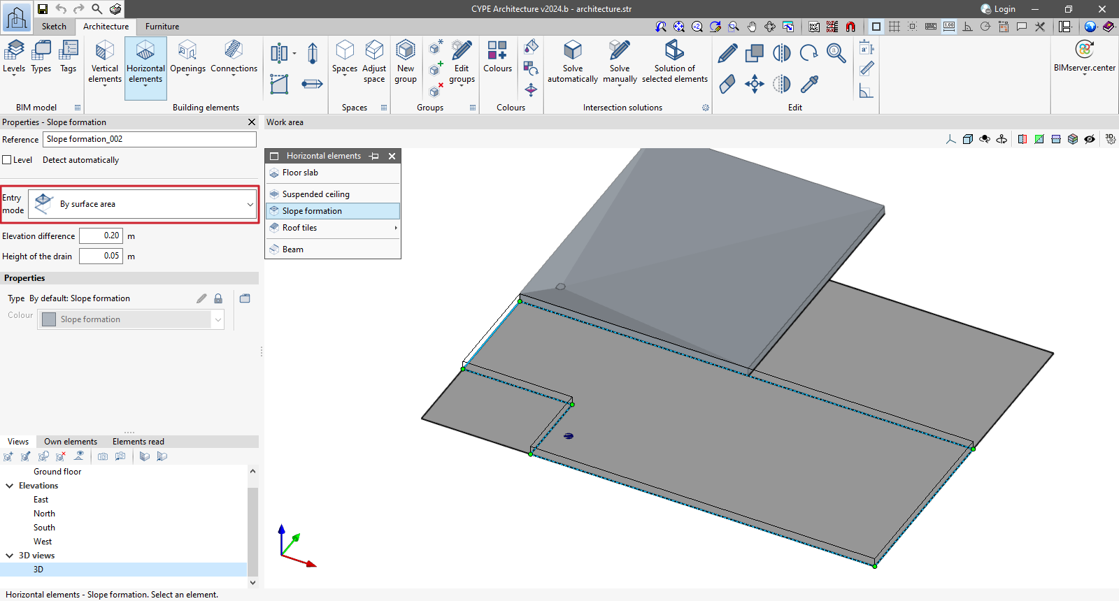
Slope formation by sketch surface area
As of version 2024.b, CYPE Architecture allows the "Slope formation" element to be entered by sketch surface area. To do this, first, select the surface area of the sketch and then select the point where the drain is located.
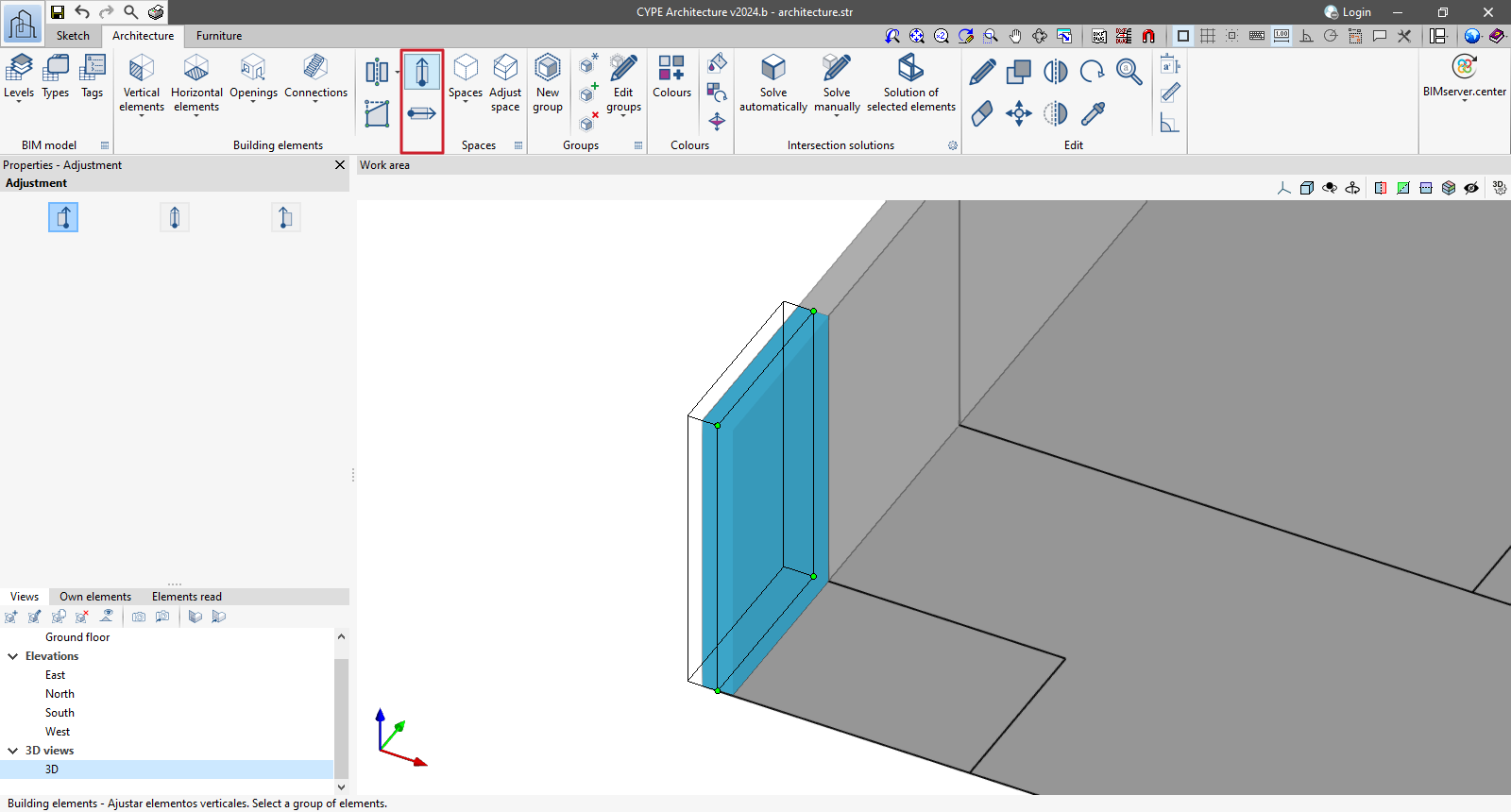
Adjustments of vertical and horizontal elements
The "Adjust vertical elements" and "Adjust horizontal elements" tools have been implemented in the "Building elements" section. They allow users to change the adjustment (to the right, to the left or centred) of one or more horizontal or vertical elements with respect to their entry line.
These tools work with elements that allow for adjustment in their entry: walls, curtain walls, louvres, railings and floor slabs.
To change the setting of one or more elements, select the new setting to be used and then select the elements to be adjusted.
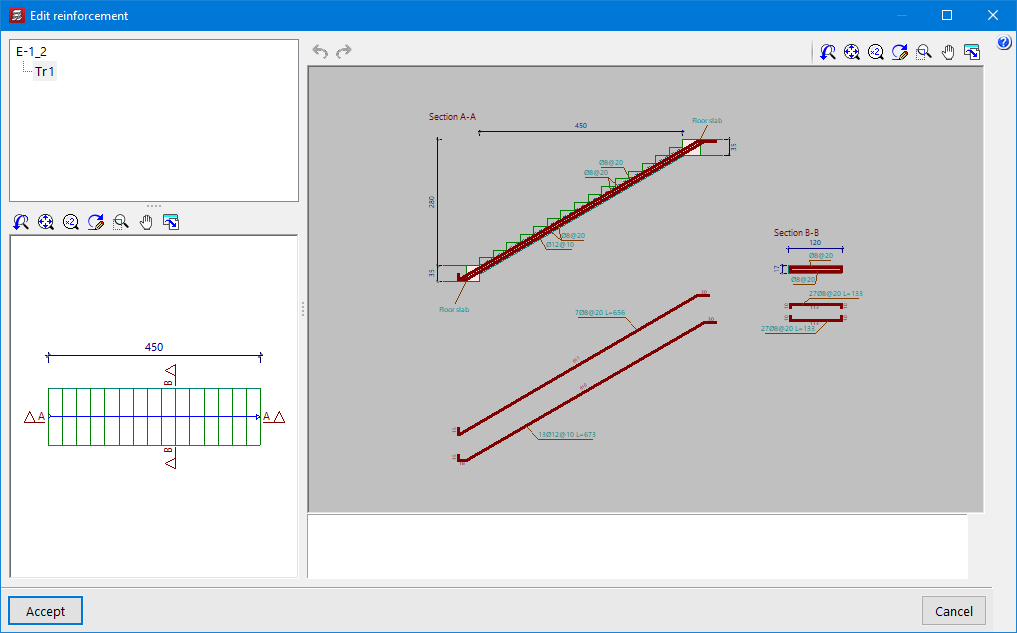
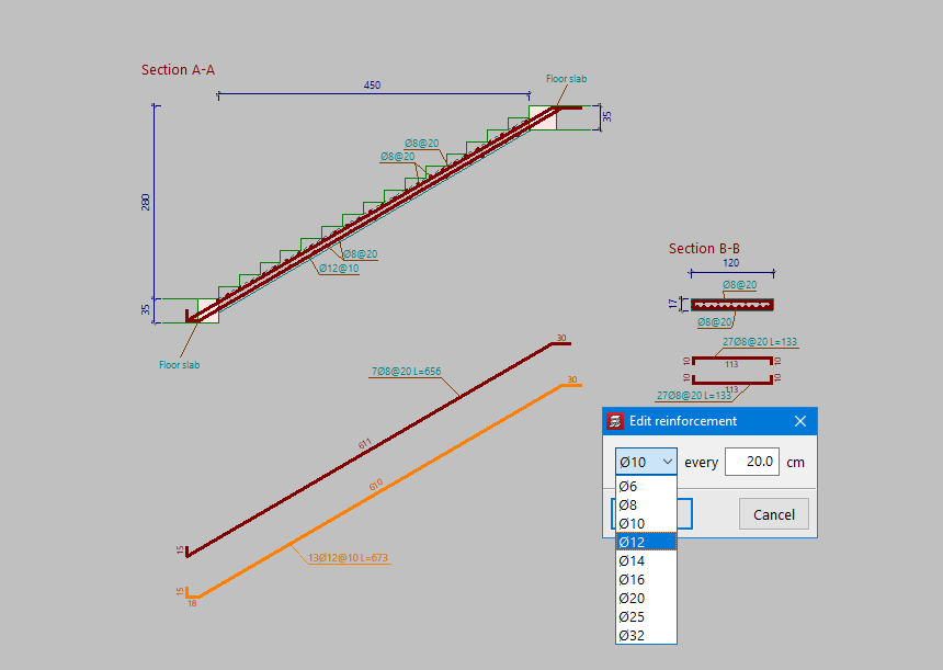
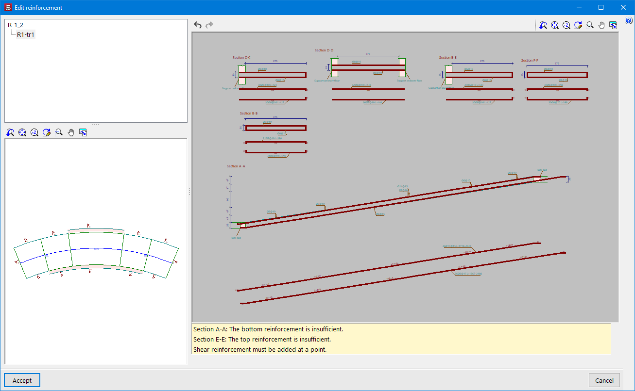
Stairs and ramps. Editing reinforcement
In the "Stairs" and "Ramps" menus, the "Edit reinforcement" option has been implemented. With this option, users can edit the diameter and spacing of the top and bottom reinforcement in each section. Once modified, a check is made to see if the reinforcement provided is sufficient. Should any of the reinforcement not be sufficient, the corresponding warnings are displayed.
Ramps. Initial screed and elevation change
Users can now enter an initial screed and elevation change in the desired ramp sections.
Ramps. Initial and final support
The support at the beginning and at the end of each section of a ramp is now optional. This possibility can be useful when the ramp is designed with lateral supports.
Locking the reinforcement of concrete sloped beams
An option to lock the reinforcement of sloped beams has been implemented in the dialogue box for editing the reinforcement of sloped beams. With this option, users can lock the reinforcement that has been calculated for a given sloped beam after it has been revised or modified. This way, when re-analysing the job, the reinforcement remains locked and the strength checks are carried out with that reinforcement.
Other improvements and corrections
CYPECAD version 2024.b includes the following program improvements and corrections for some specific cases:
- Exporting ramp reinforcement.
- An option has been added to allow the use of the combinations of the CIRSOC - 05 standard when selecting the AISC 360 rolled steel or AISI-S100 formed steel standards.
- The generation of loads corresponding to the tendons in waffle slabs with post-tensioned reinforcement has been improved in cases where the tendon passes through a drop panel. Previously, the difference in the eccentricity of the drop panel with respect to the waffle slab was not taken into account.
- The grouping of portal frames has been improved by obtaining drawings of them. The comparison criteria have been modified to allow more precise detection of portal frames with the same geometry and reinforcement.
- An error that could occur when editing the foundation elements of some example jobs has been fixed. This was due to the fact that these jobs did not have all the files that had been generated during the analysis in any of the jobs.
- An error in the export of reinforcement bars has been fixed. This could occasionally happen when a rebar had a very gentle change of direction.
- An error that occurred when the "Number of colours" was changed to 24 in "Colours for the representation of contour plots" has been fixed.
- The report for rectangular slabs has been improved. In some cases, when the reinforcement provided is due to the minimum amount, it was not displayed correctly.
- An error that occurred in the "Solution of the equation system" phase of the analysis and which prevented this phase from being completed has been corrected. In the case detected, it occurred in a linear element of more than 12 metres (with 57 force points) of a job with 29 load cases and 87 vibration modes.
- An error that occurred when editing a bolt-type punching shear reinforcement, defined as "Radial", has been corrected. The error occurred if the number of rows was 1 and was changed to a different value.
- An error that occurred when selecting "Quantities" in "BIMserver.center > Share" if there were steel sections with haunches in the job has been fixed.
- The seismic and capacity checks of the ACI14 and ACI19 and Bolivia-20 standards have been improved when the category is C.
- The "Delete all the elements from the list" button has been added to the punching shear studs library panel.
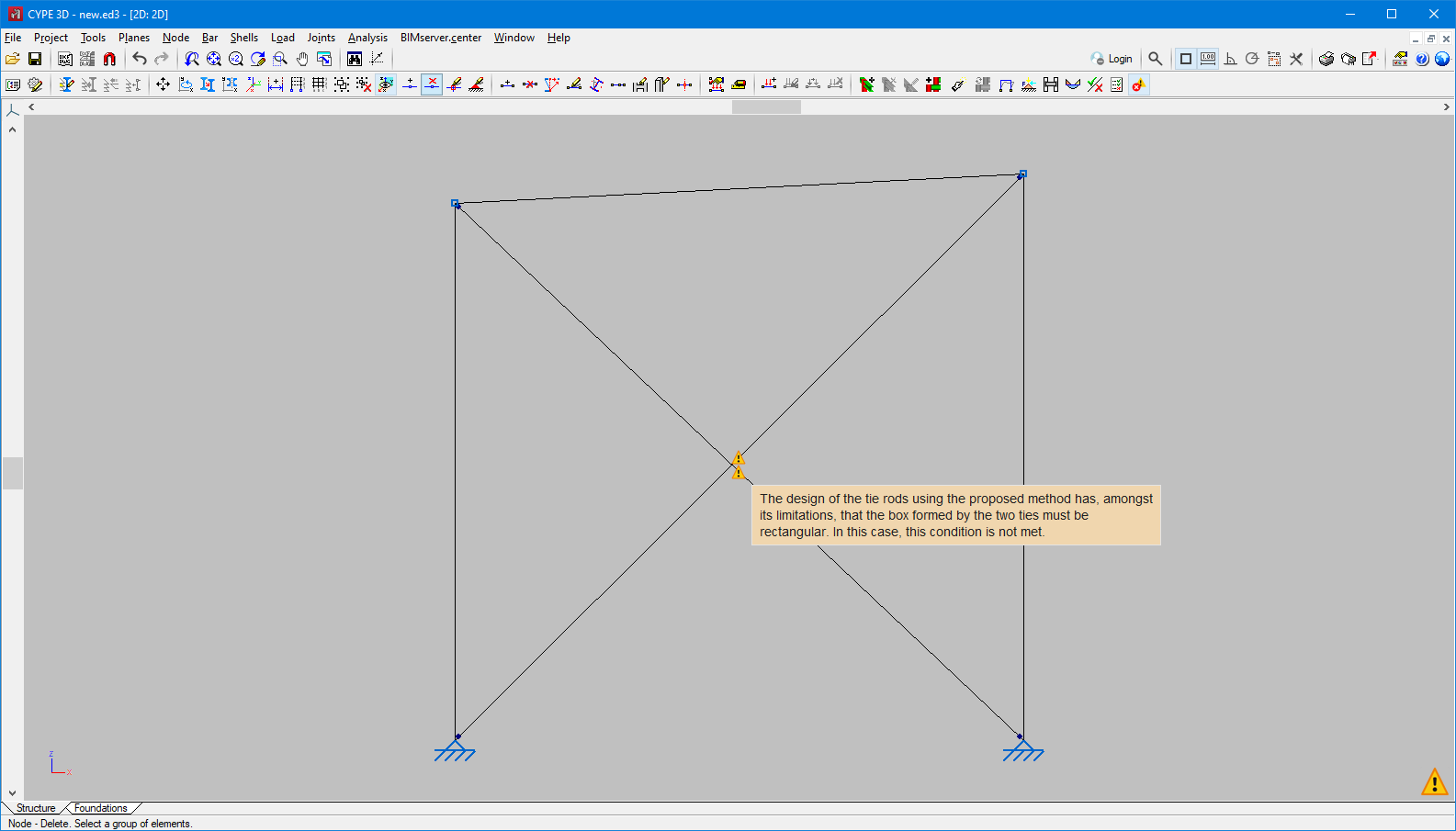
Warning for non-rectangular braced frames
In versions prior to 2024.b, if the braced frame was not rectangular, a warning message was displayed and the job could not be analysed. In the help text on the analysis of tie rods, the method’s validity conditions are listed. Among the conditions, the following is mentioned:
"The diagonal forms part of a braced frame framing the four edges, or three, if the stiffening bars reach two exterior fixities. Additionally, each panel must form a rectangle (the four internal angles being right angles)."
As of version 2024.b, the warning indicating that the braced frame is not rectangular is still displayed, but the job is not prevented from being analysed. The aim is to let users analyse structures even if the frames are not rectangular, but a warning is displayed. When the frames are not rectangular due to slight variations in their angles, the result may be acceptable depending on the structure.
However, if there are very deformed frames, the analysis is still blocked due to this warning. This situation will occur when the cut-off point between the tie rods is further from the midpoint than 10% of the tie rod length, or when the difference in tie rods is greater than 20%.
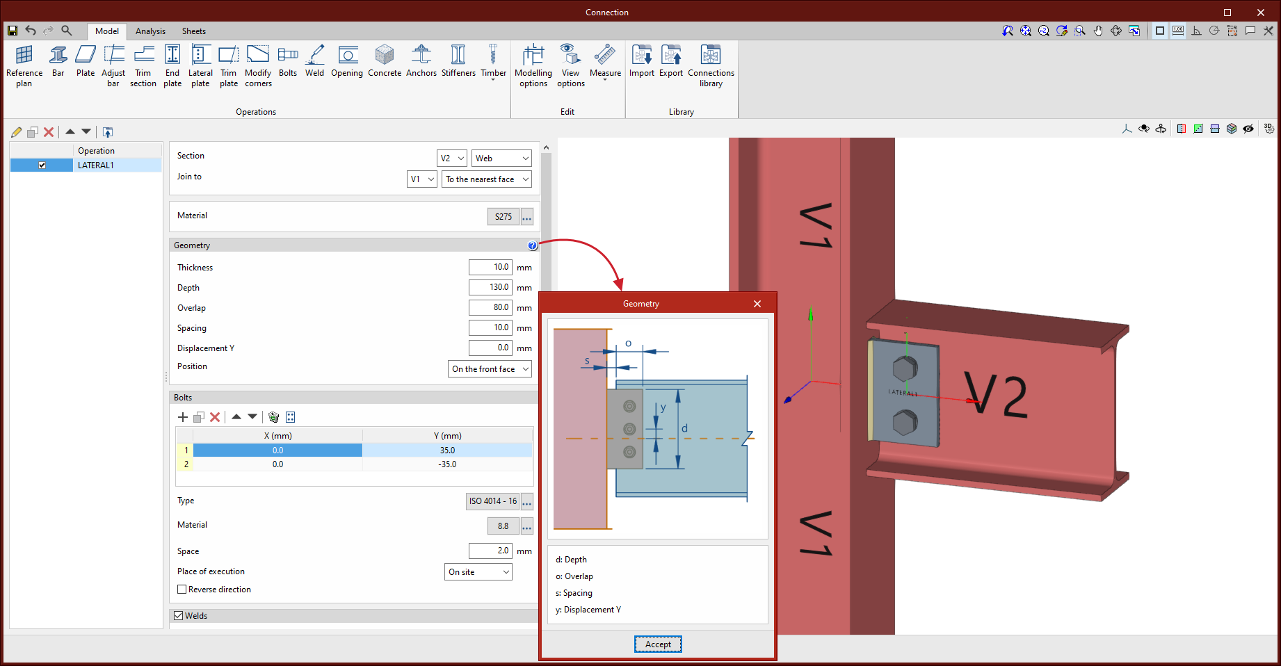
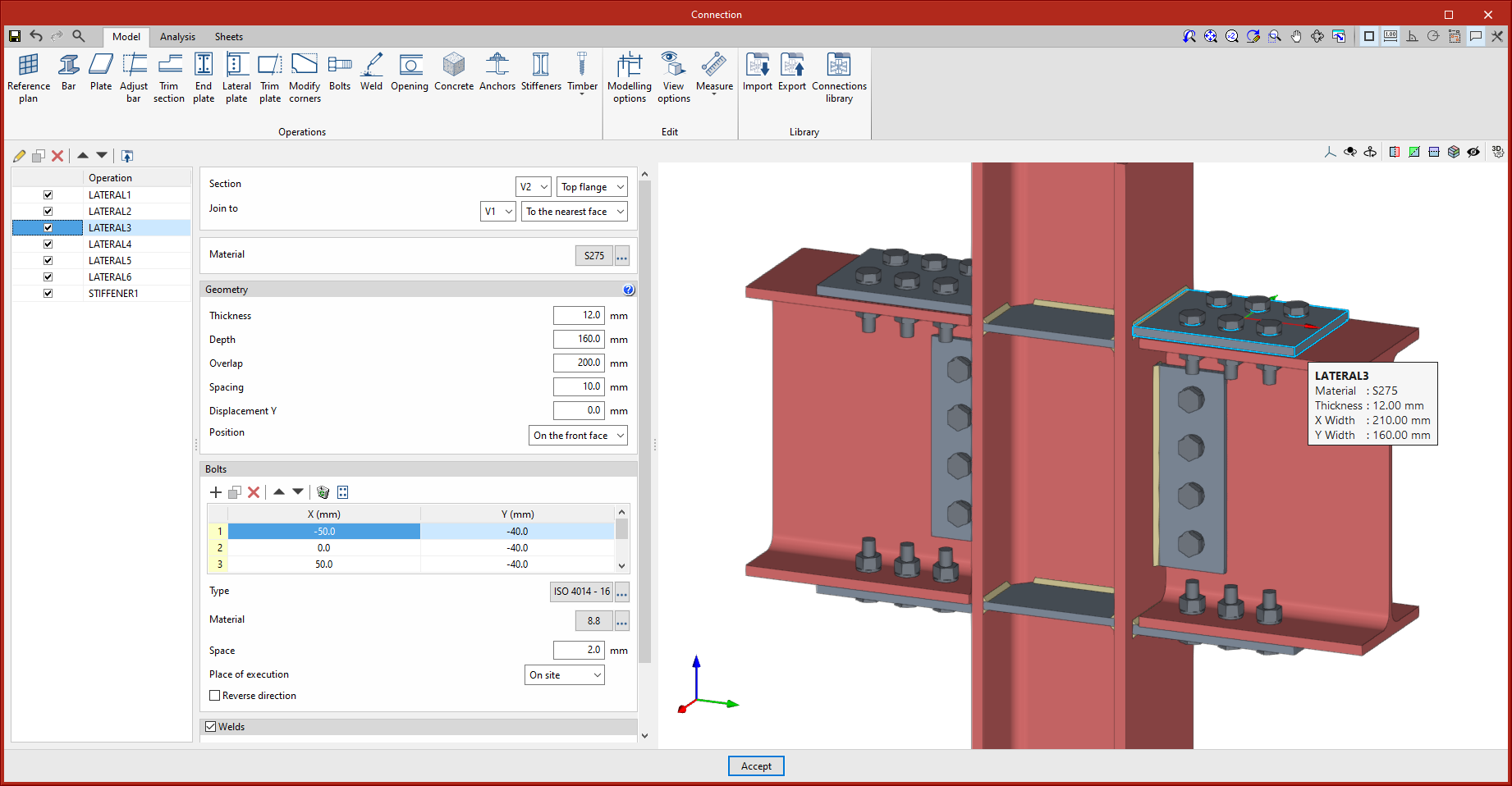
New operation: "Lateral plate"
The "Lateral plate" operation has been implemented. This allows sections to be joined together by means of a plate welded to one of them and bolted to the other. Up until version 2024.b, 4 operations were necessary for each lateral plate, an adjustment of the secondary bar, the insertion of a plate, a weld between the plate and the main bar and a group of bolts between the plate and the secondary bar. With this implementation, one of the most commonly used types of connection is automated.
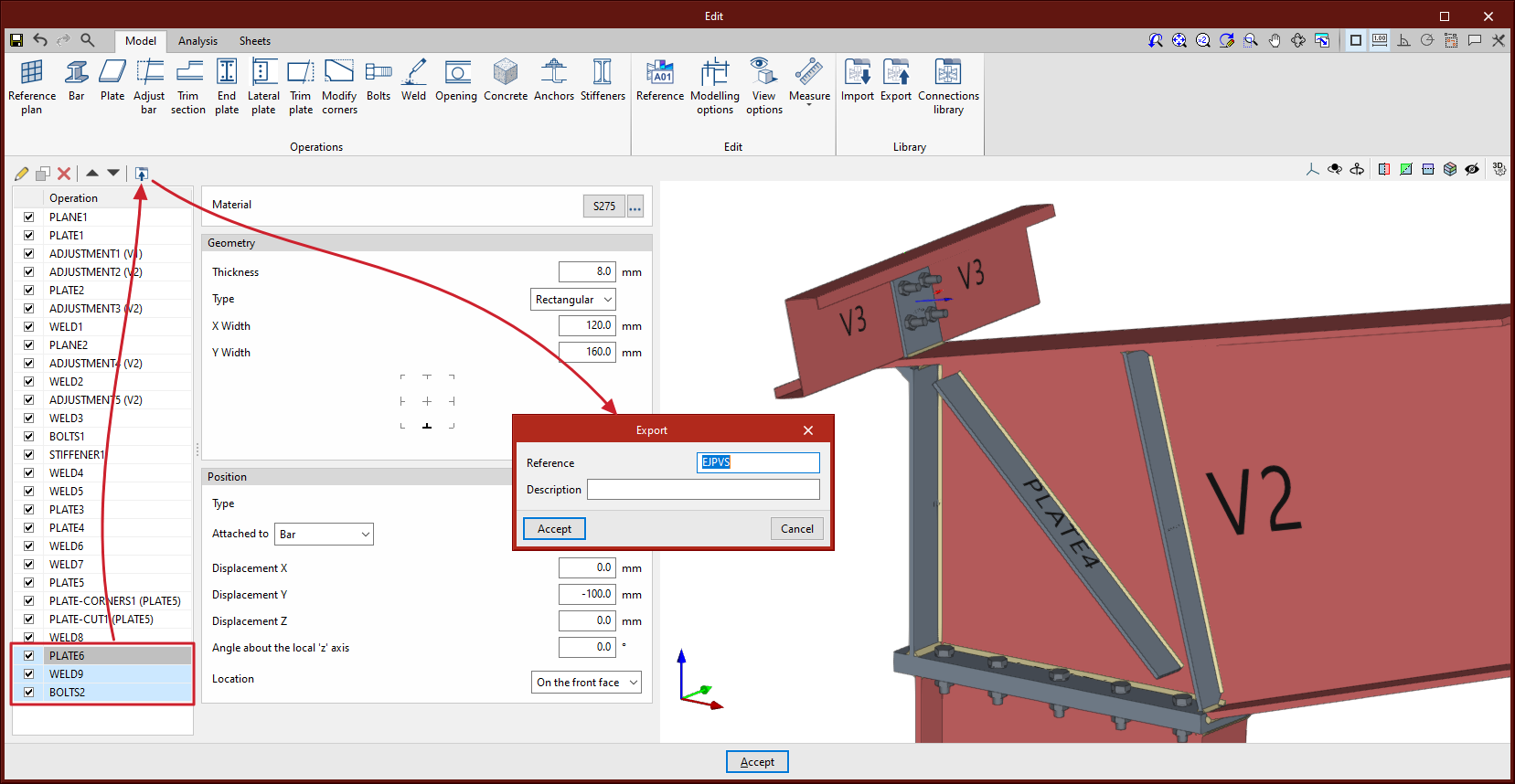
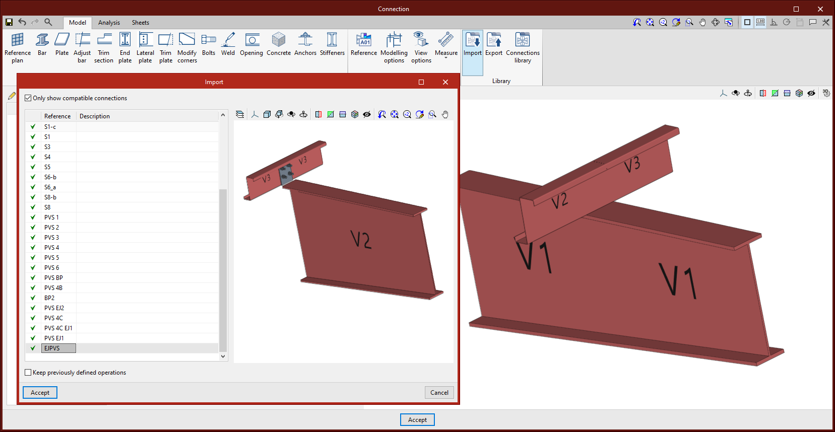
Exporting a selection of operations to the connection library
In version 2024.b, a new option has been implemented to export a selection of operations to the connection library. This export creates a library connection with the selected operations and the sections involved in these operations.
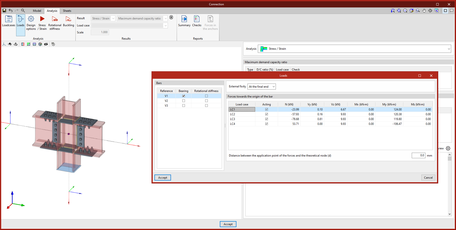
Loads on continuous bearing bars
As of version 2024.b, the continuous bars defined as "Bearing" bars of the node, offer the possibility of defining forces at the end that has no external connection defined.
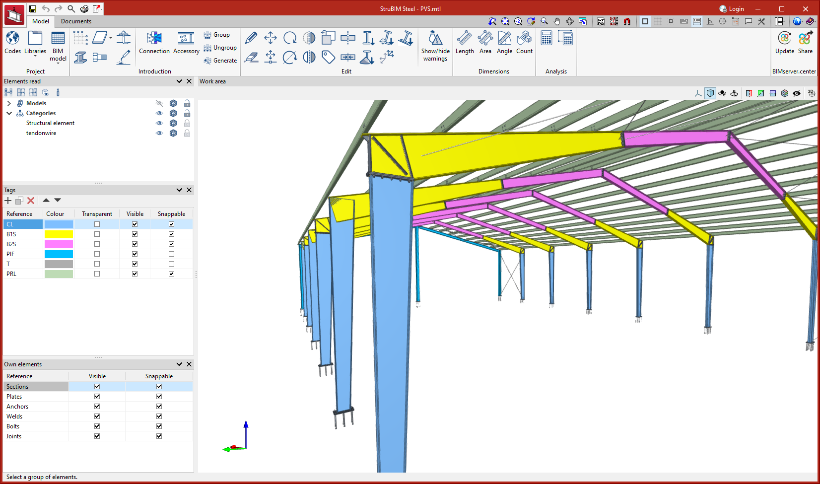
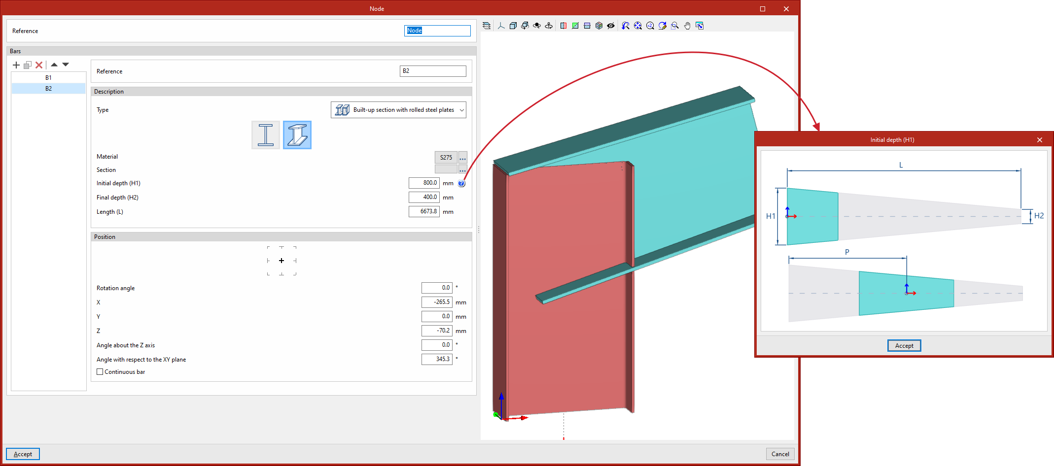
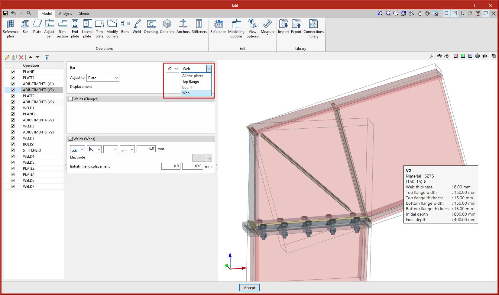
Built-up sections
In version 2024.b, the section types supported in CYPE Connect and in the StruBIM Steel connection editor have been increased. Built-up constant depth I sections and built-up variable depth I sections, both with the possibility to define different flanges, have been implemented.
In CYPE Connect, the new type "Built-up section with rolled steel plates" has been added. When it is selected, the available sections will be the variable depth I sections and variable depth I sections. To define the variable depth I sections, the initial edge, the final edge and the length of the bar must be specified. When the bar is continuous, the position where the connection will be placed must also be defined.
In the connection editor (both in CYPE Connect and in StruBIM Steel), when the selected bar is a built-up section, the "Adjust bar" operation allows users to adjust all the plates of the section or only the selected plate.
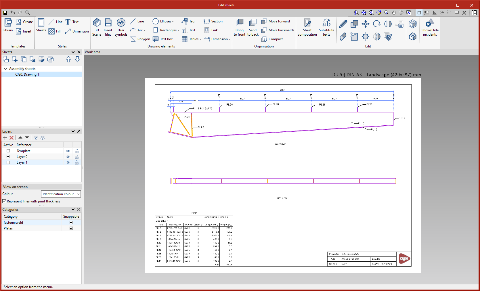
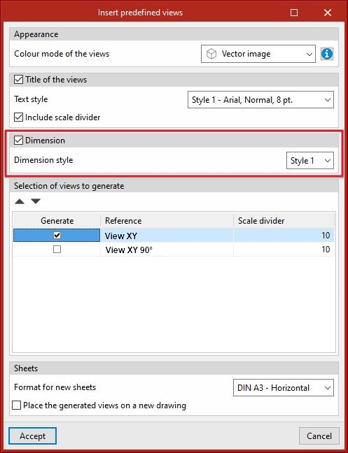
Automatic dimensioning
In version 2024.b, sections and plates can be automatically dimensioned in part sheets, and plates can be automatically dimensioned in connection sheets. For this purpose, in the "Insert predefined views" dialogue ("3D Scene" > "Insert predefined views"), the "Dimension" section has been implemented. Here, the "Dimension style" is defined. When accepting the "Insert predefined views" dialogue with the "Dimension" option activated, the dimensions of the inserted predefined views of part sheets are automatically added along with the dimensions of the predefined views of plates on connection sheets.
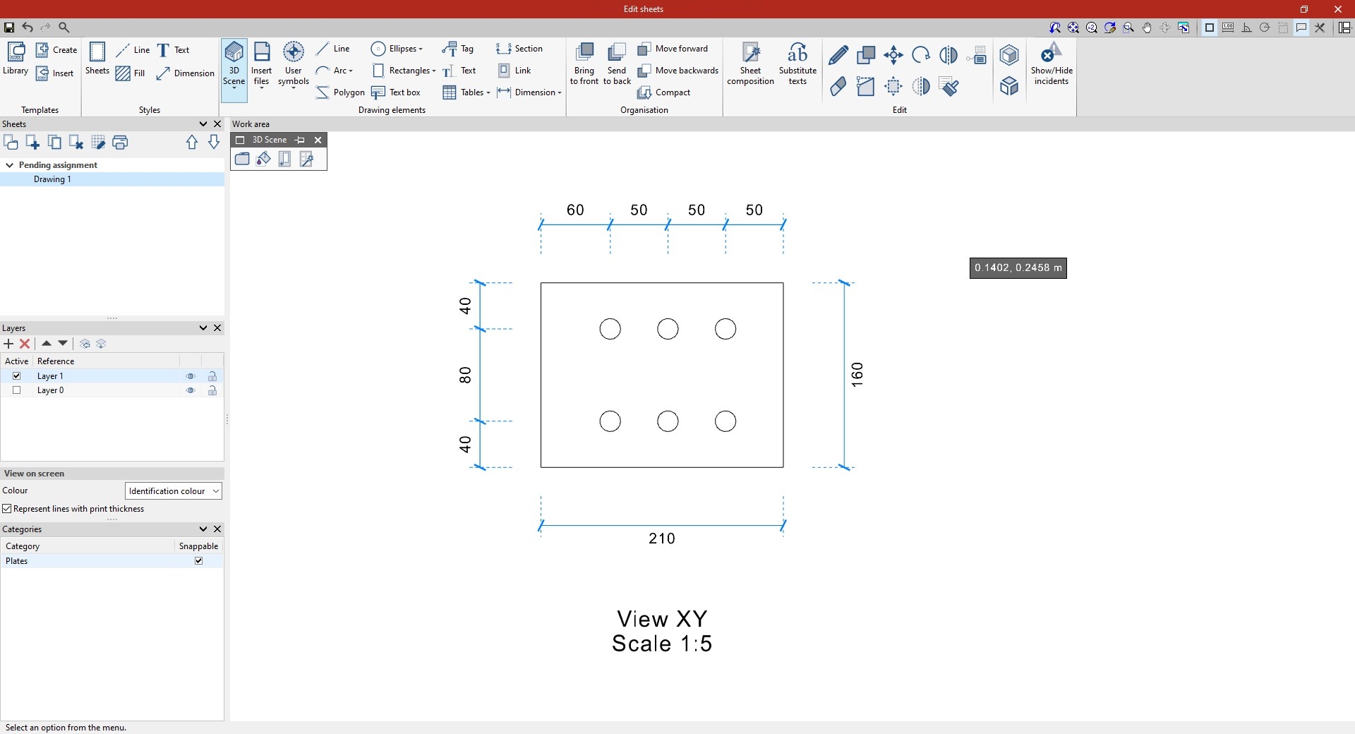
Deleting continuous dimensions intermediate points
An option to delete continuous dimensions intermediate points has been implemented. When selecting the "Modify geometry" option and clicking on a continuous dimension, the dimension intermediate points will be shown in red. If an intermediate point is selected, it will disappear and the two adjacent sections will be connected.
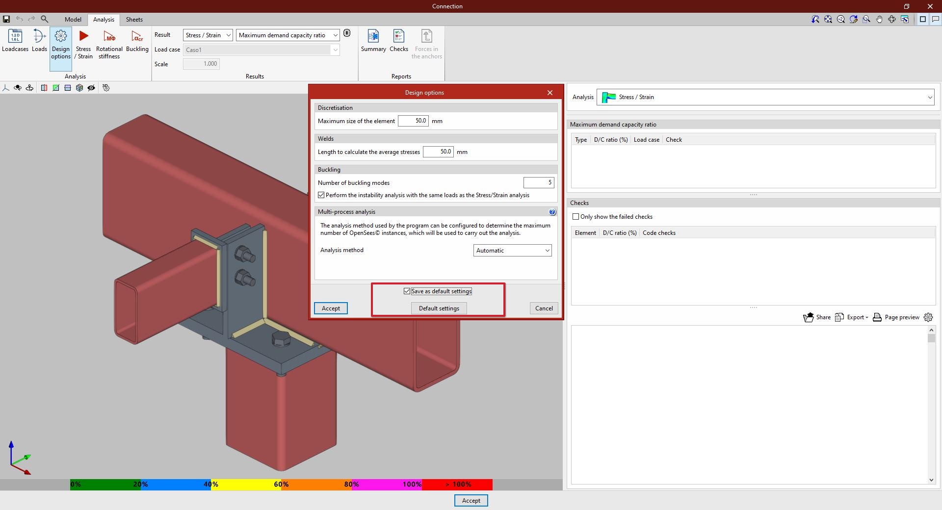
Defining the default settings in "Design options"
As of version 2024.b, the "Design options" panel includes the "Save as default settings" option. If this option is activated and the panel is accepted, all the settings in this dialogue are saved as default values, so that any subsequent new job will initially have the same values.
Optimising the use of sheets
A series of optimisations have been implemented in version 2024.b in the use and management of sheets. This reduces waiting times when accessing the sheets and using their tools.
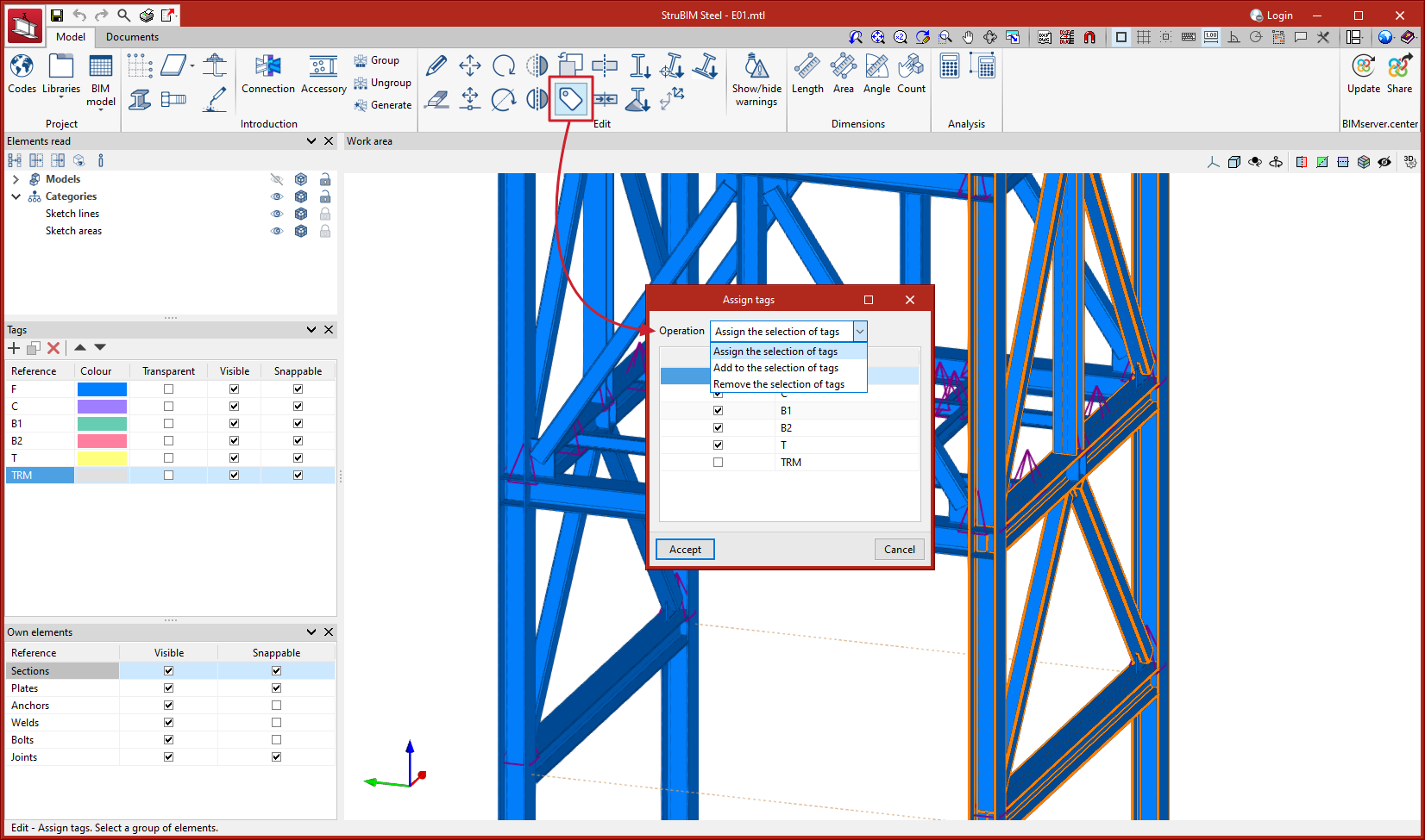
Assign tag
Up until version 2024.b, the "Assign tag" tool allowed users to assign a selection of tags to a selection of elements. The selected tags were applied to the elements and the unselected tags were deleted. In version 2024.b, new options have been added:
- Assign the selection of tags
This option offers the same result as in previous versions. Selected tags are assigned and unselected tags are deleted if they were previously selected. - Add to the selection of tags
The selected tags are added to the elements, keeping the previously defined tags. - Remove the selection of tags
The selected tags are removed from the elements, keeping the rest of the tags.
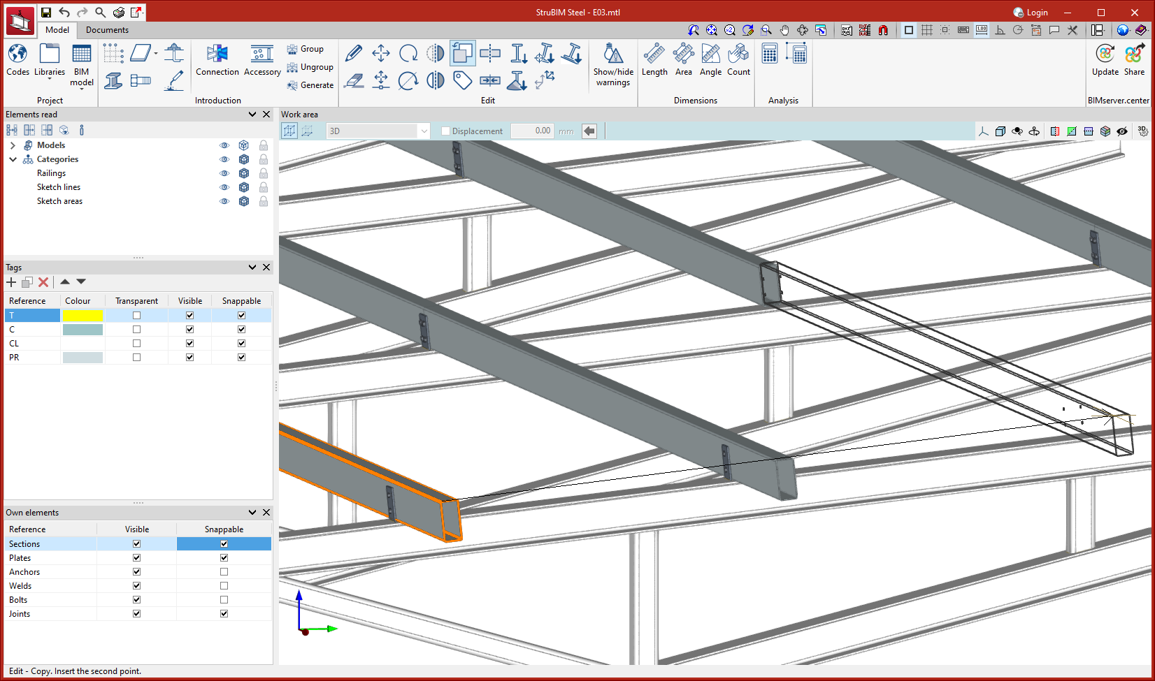
Improved "Copy" tool
Up until version 2024.b, when using the "Copy" tool, any element except those previously entered with this tool could be selected as a reference. As of version 2024.b, the "Copy" tool allows the selection of previously copied elements as a reference.
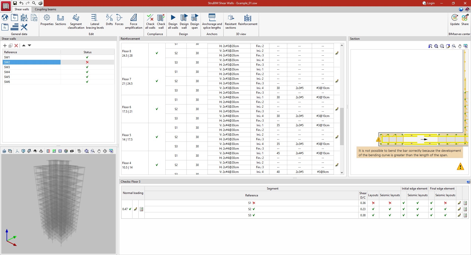
Warning message on bars with geometrical errors
As of version 2024.b, a warning is displayed when the bars of shear wall sections have an incorrect layout.
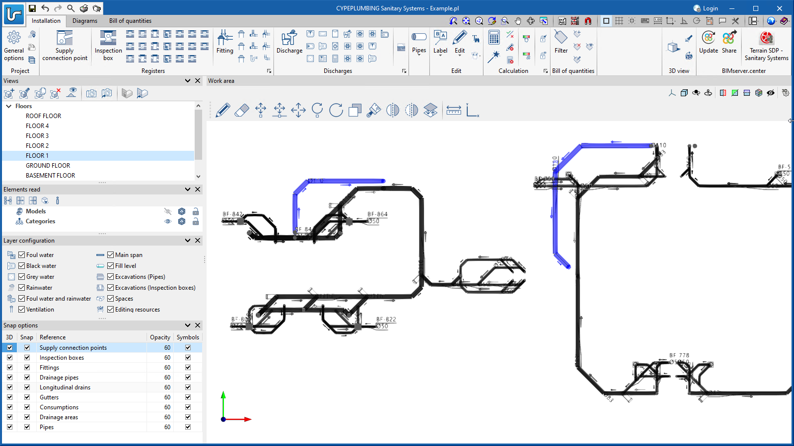
Entering the system in the new 3D environment
CYPEPLUMBING Sanitary Systems was designed for working in a 3D environment with the possibility to work on configurable workplanes.
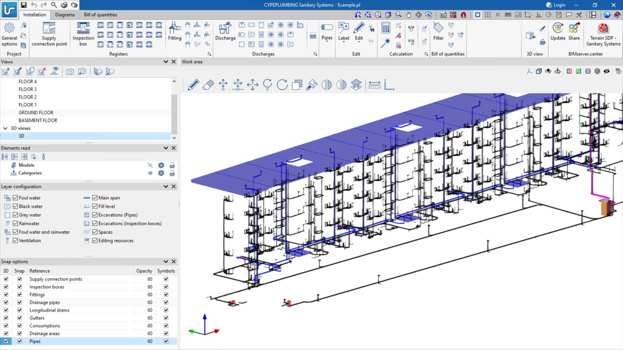
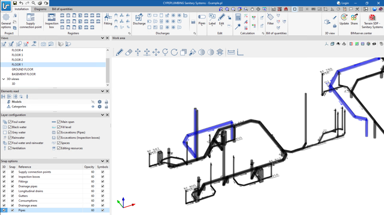
It enables the system design to be carried out on 2D templates from the BIM model or imported from the program in DXF, DWG, DWF or various image formats (JPEG, JPG, BMP or WMF).
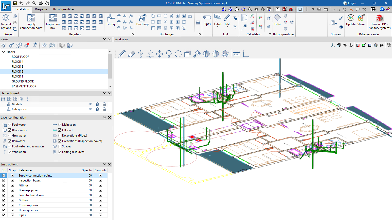
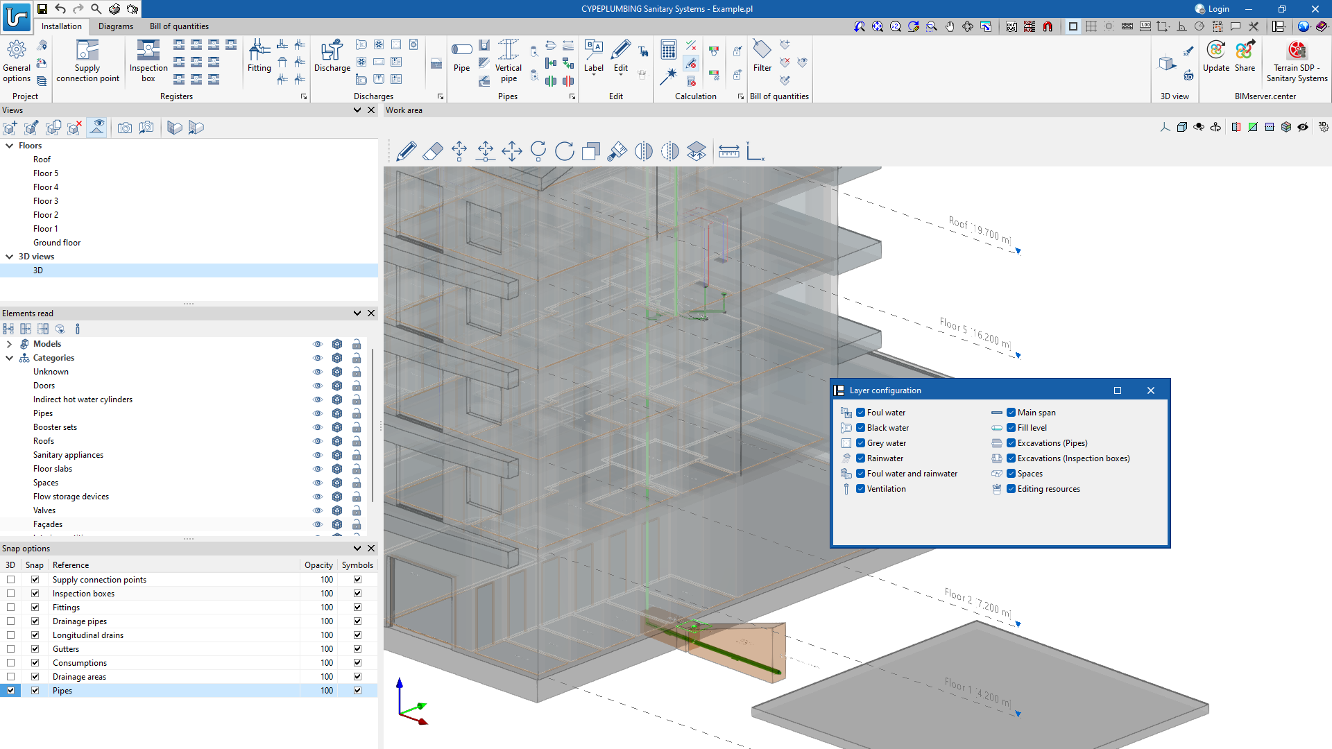
Users can also work in layers with the different networks and other relevant information:
- Foul water
- Black water
- Grey water
- Rainwater
- Foul water and rainwater
- Ventilation
- Main span
- Fill level
- Excavations (Pipes)
- Excavations (Inspection boxes)
- Spaces
- Editing resources
The "3D Views" can be displayed with symbols in 3D formats and the level of opacity of the elements can be controlled.
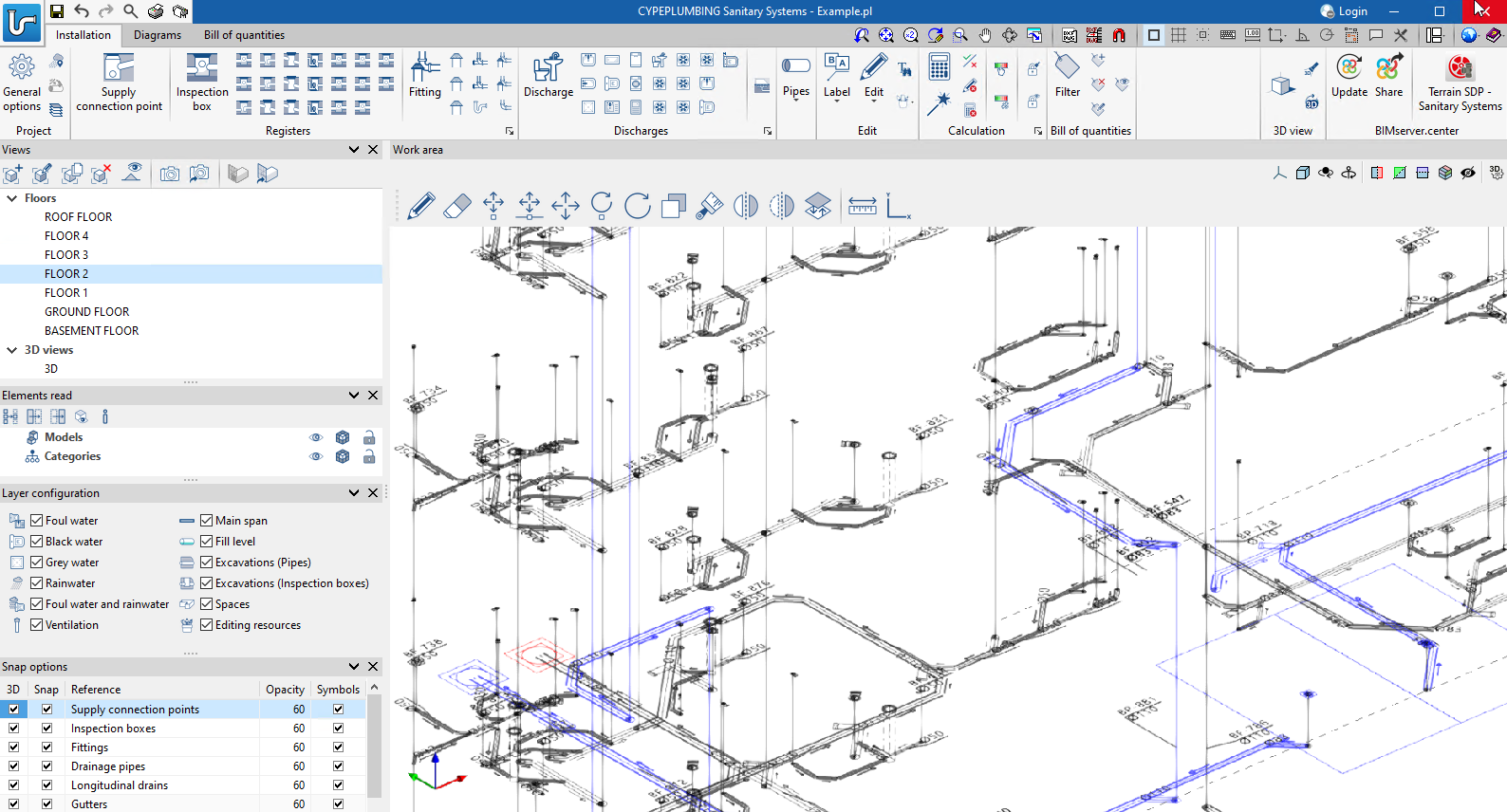
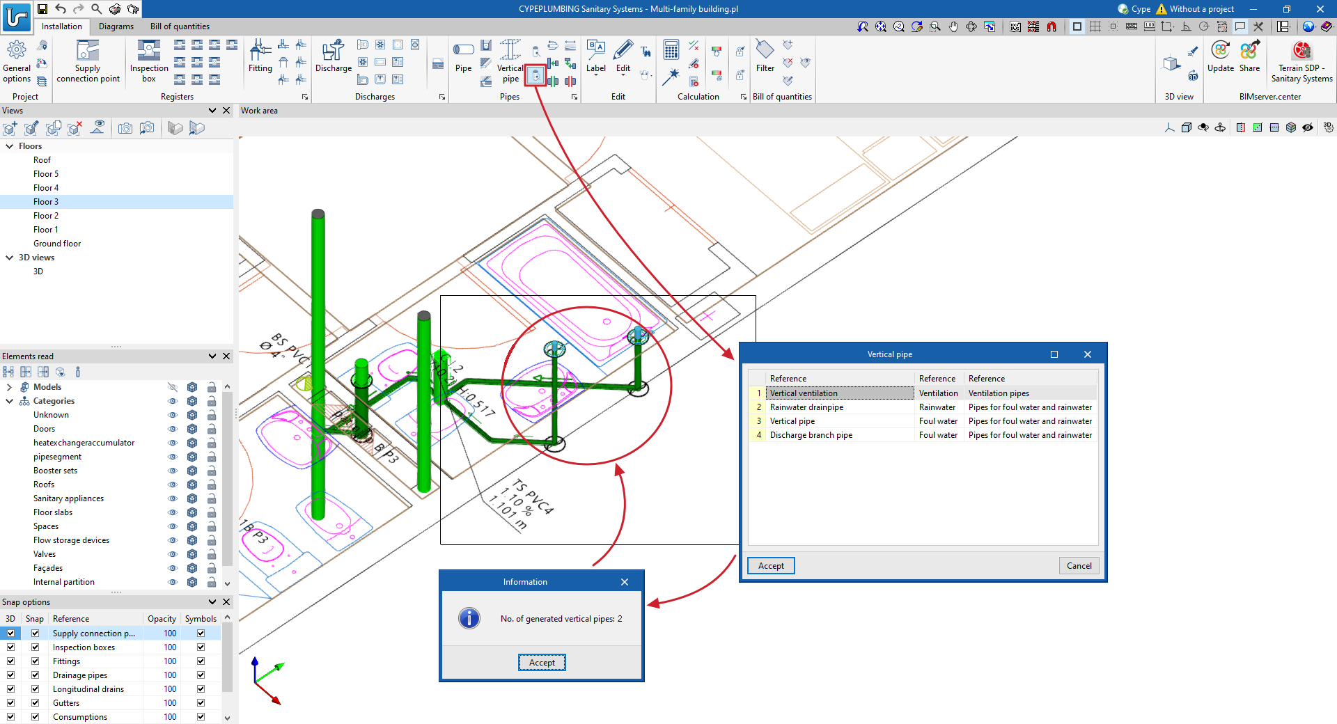
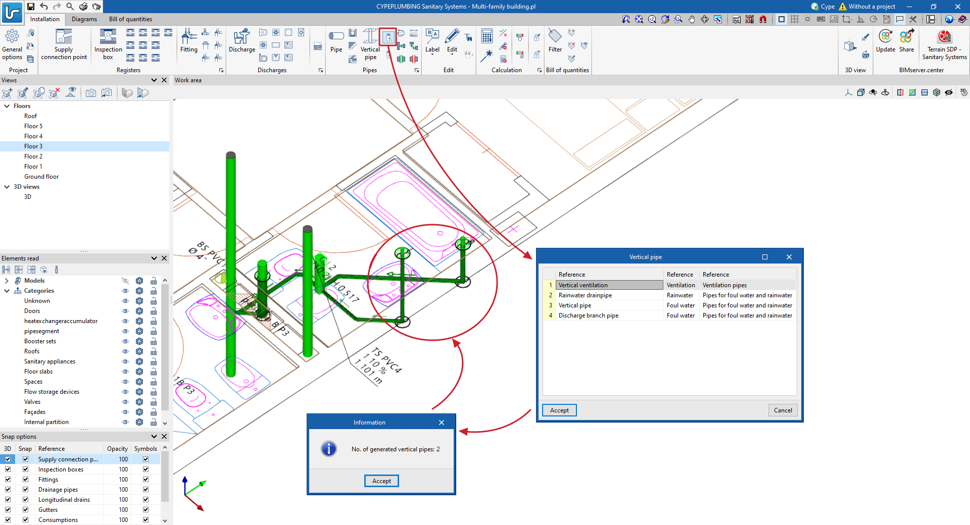
The elements and pipes can be entered in the "3D views" or in the workplanes. In either entry mode, vertical pipes can be generated with ease.
- In the (X,Y,Z) environment
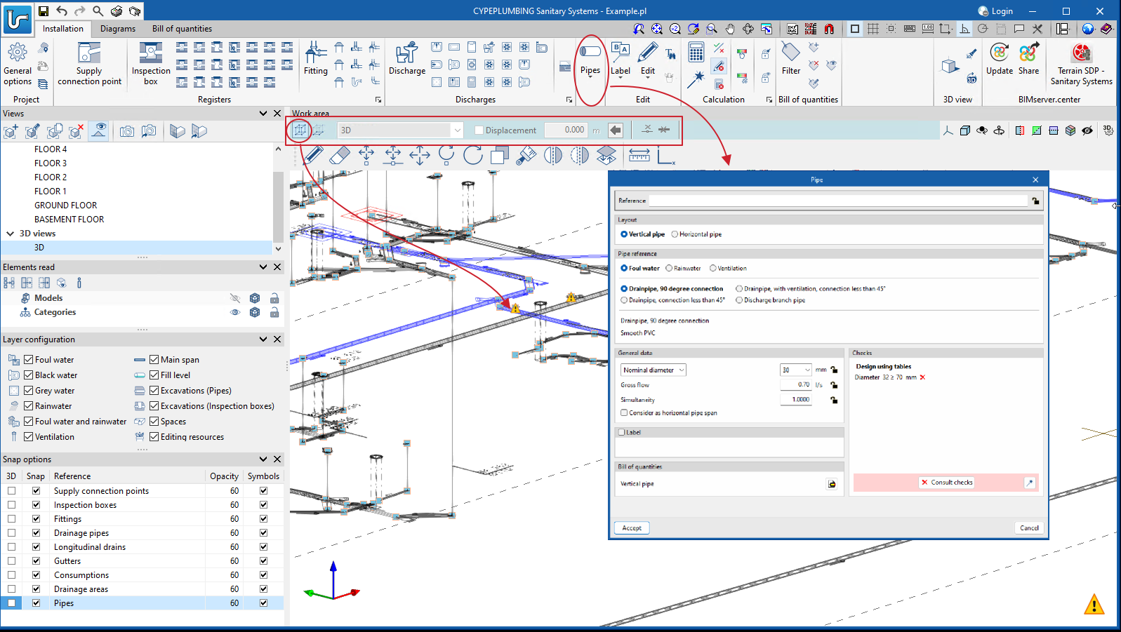
- In the (X,Y) environment
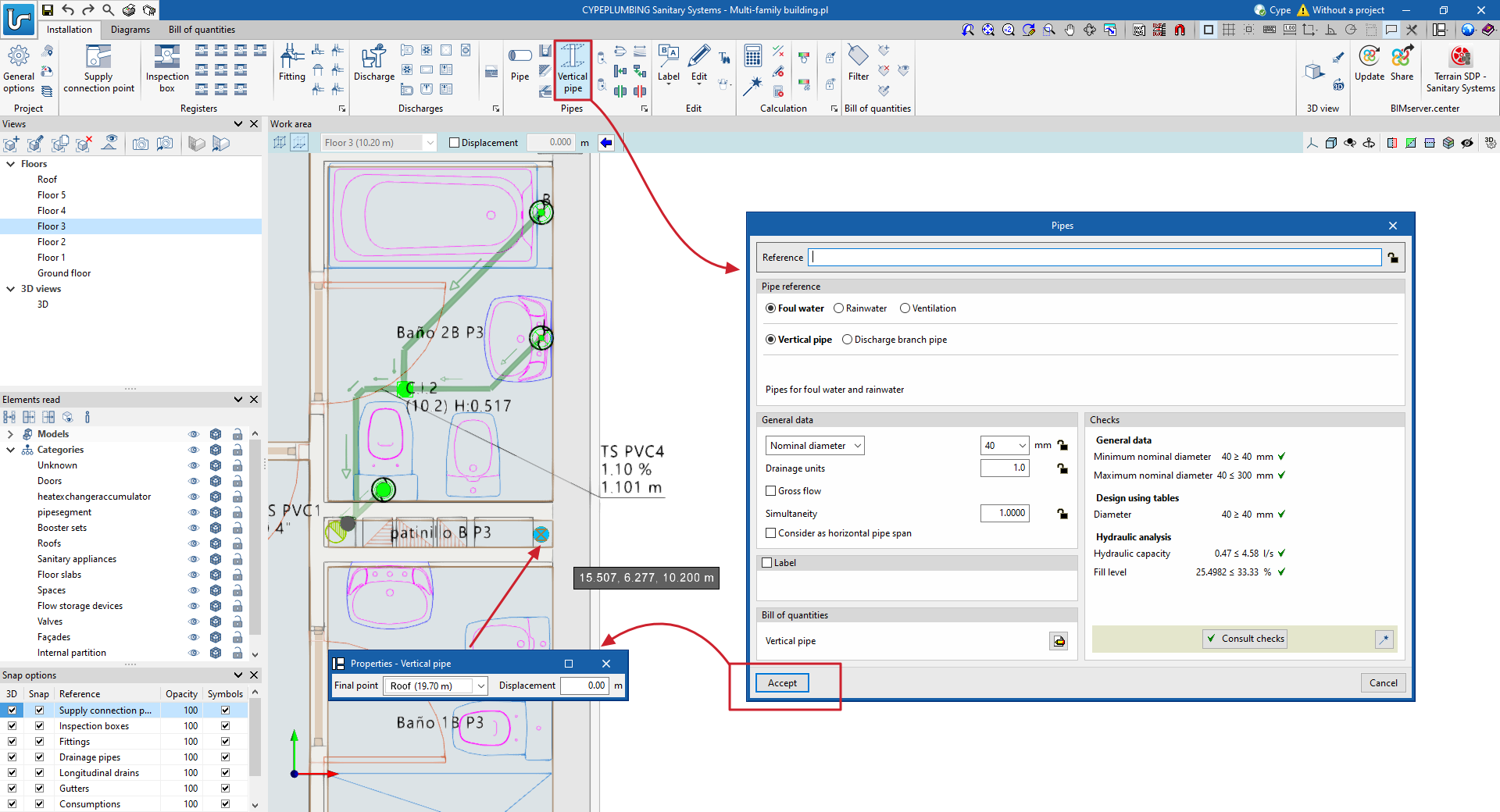
- By generating vertical branches to discharges in automatic editing. This mode has two tools. One allows users to select elements per window and the other detects all discharges without a vertical branch.
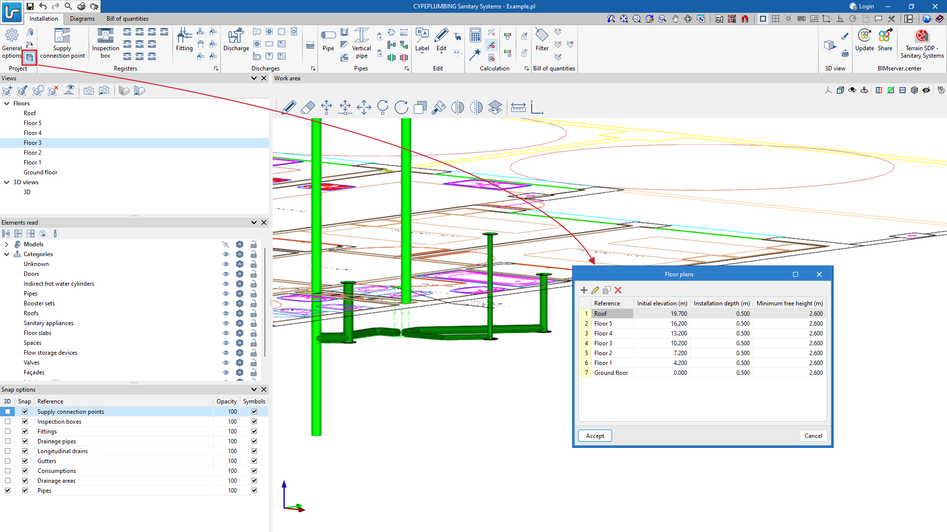
The depth of the initial system for each floor is defined in "Project" > "Floor plans".
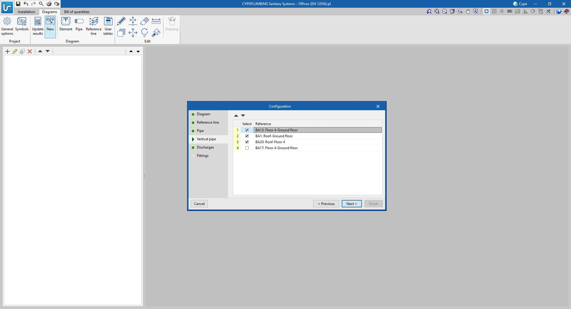
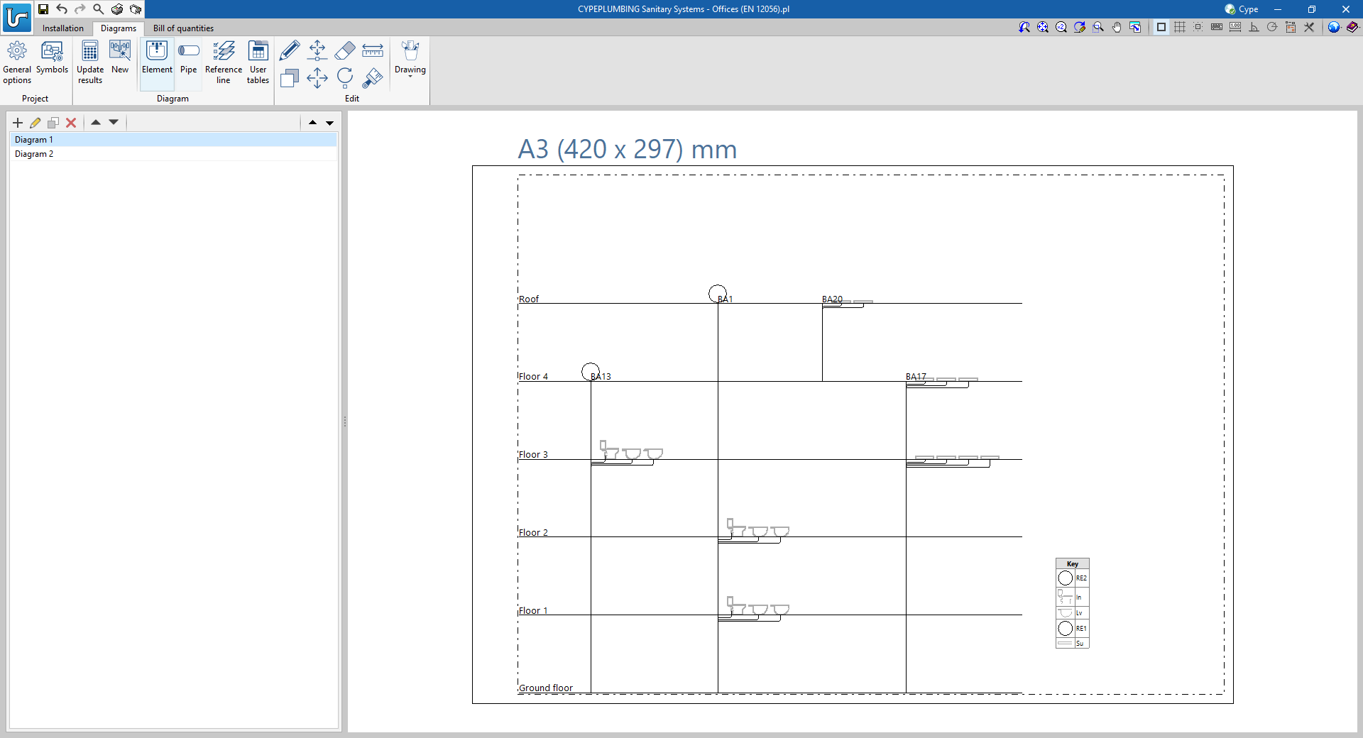
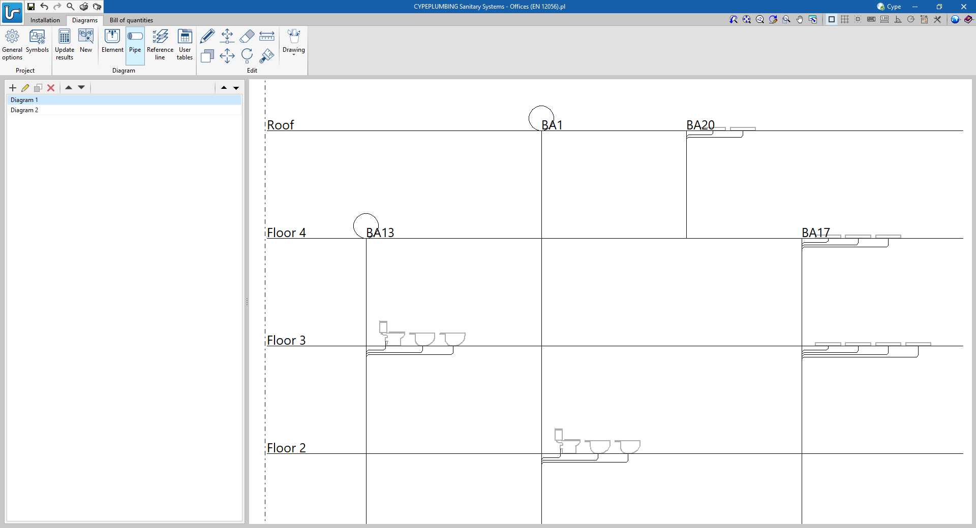
Automatic generation of vertical pipe diagrams
In CYPEPLUMBING Sanitary Systems, a new tab has been added for defining system diagrams.
Users can import and generate symbols for the diagram.
Symbols can also be assigned to discharges and aeration valves of the system entered in the "Installation" tab.
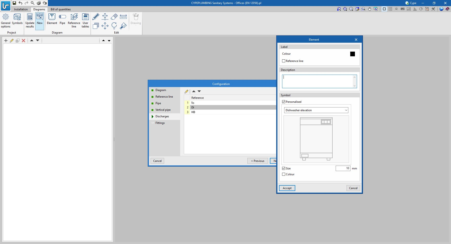
All of this allows users to automatically generate vertical pipe diagrams.
New drains catalogue
As of version 2024.b, drain catalogues can now be entered. Previously, only one drain could be entered as a single generic discharge. Now, any type of drain from a manufacturer's catalogue can be included in the system.
The manufacturer's catalogue currently included in the program comes from Aliaxis, although users can enter their own catalogues or those of other manufacturers with the data provided by the latter.
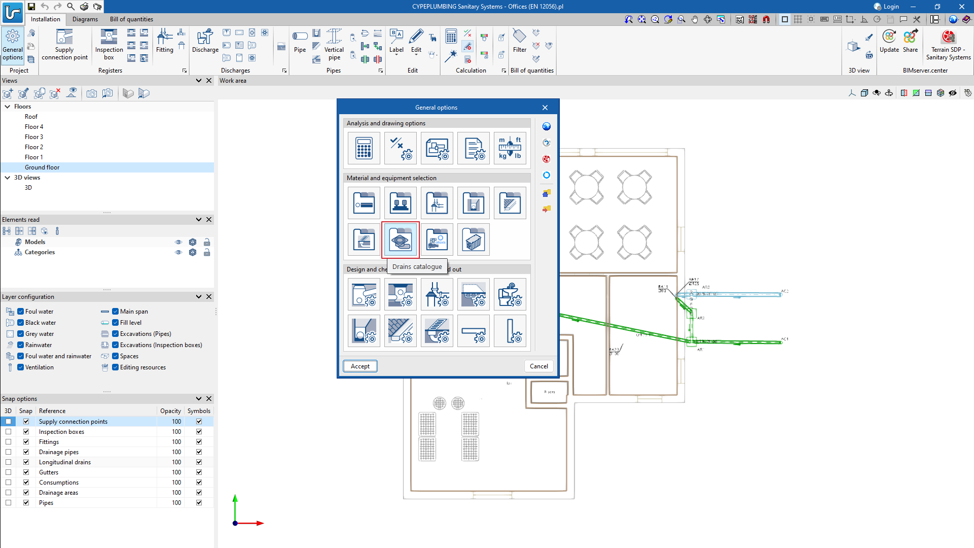
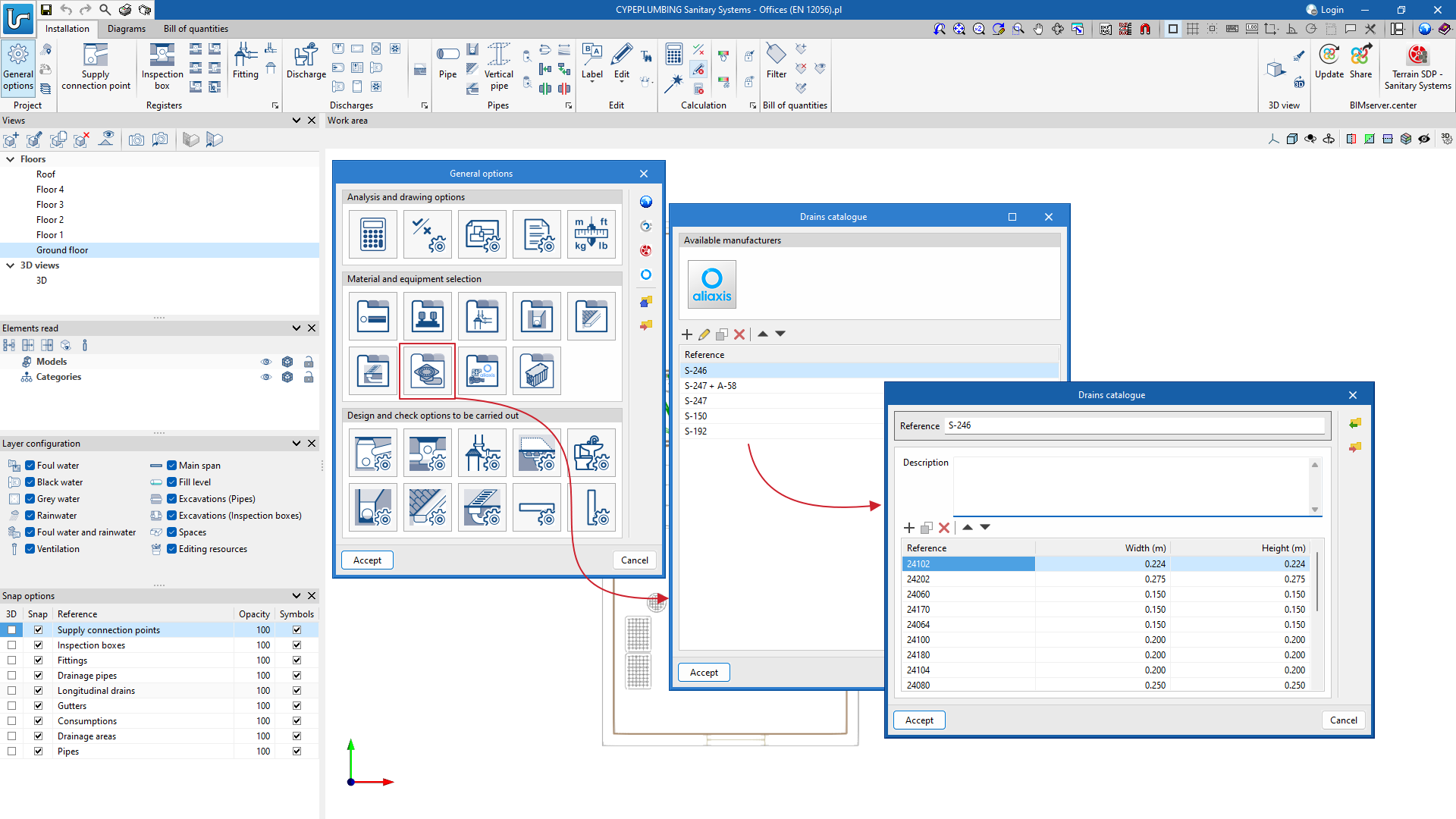
In "Technical properties" ("General options" > "Design and check options to be carried out") users can choose the corresponding material of the drain from those defined in the library of drain catalogues.
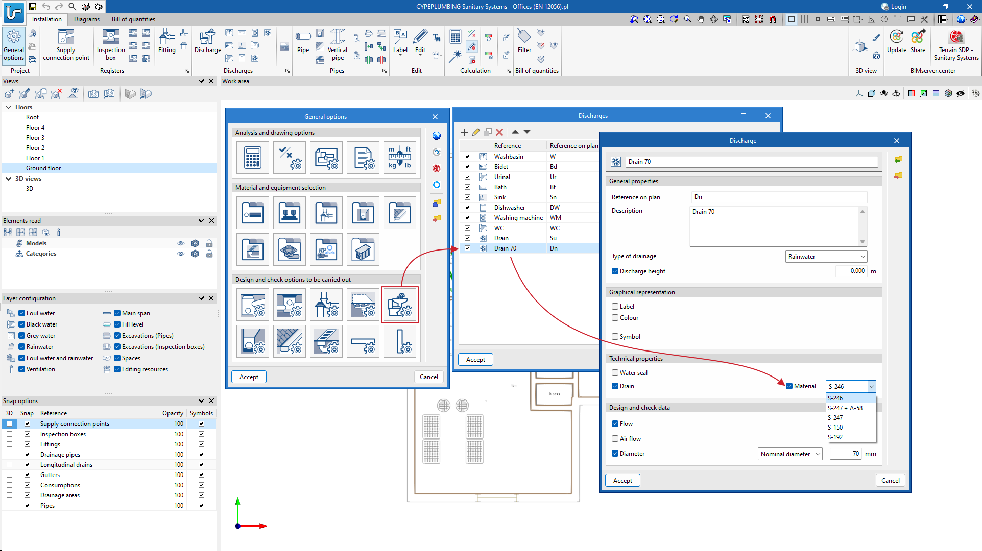
New catalogue of pumping systems in precast inspection hatches
As of version 2024.b, users can define the dimensions of a prefabricated inspection hatch for each element in the pumping station catalogue.
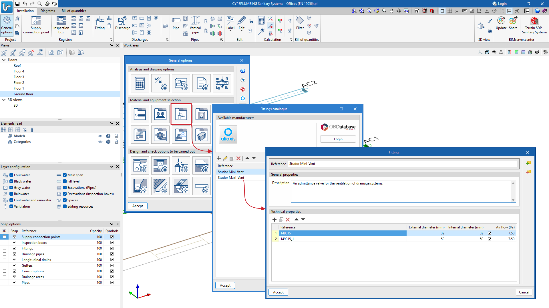
New catalogue of "Aeration valve" type fittings and checks
In previous versions, the program allowed users to create a catalogue of "Aeration valves" by defining the interior and exterior diameters of these elements. Now, in version 2024.b, users can also specify the admissible air flow rate for each valve.
Furthermore, in version 2024.b, the Aliaxis aeration valve catalogue has been incorporated, where all the characteristics of its air admittance valves are predefined.
The program now also checks whether aeration valves need to be entered.
To do this, users must activate the "Aeration valves" option in "General options" > "General checks".
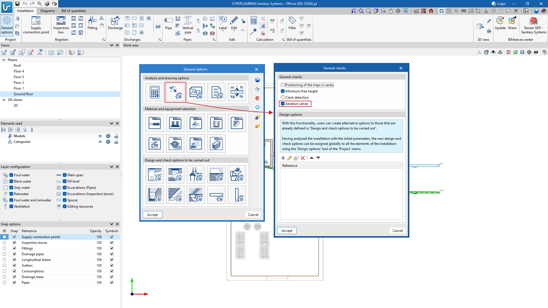
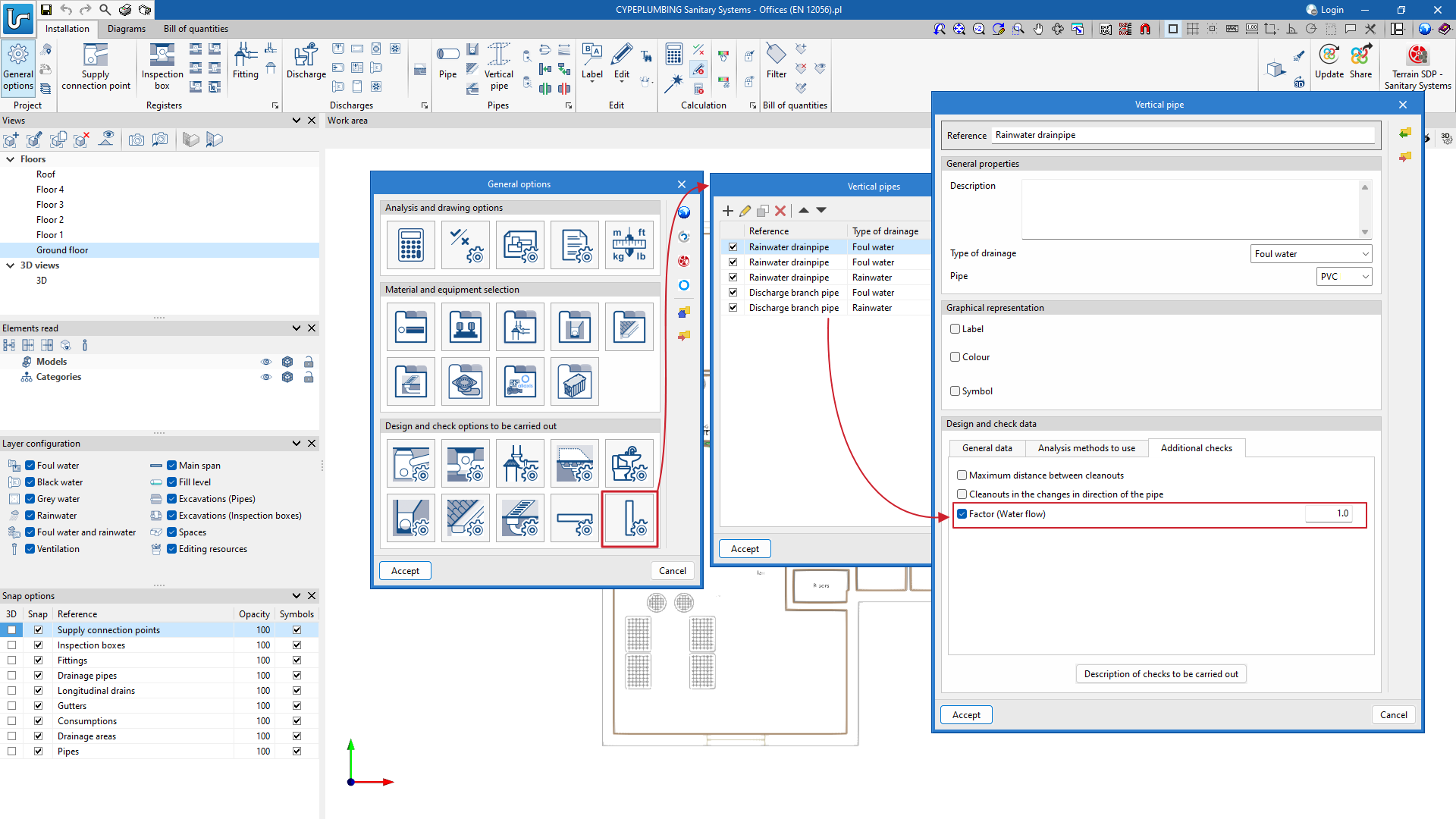
Furthermore, the "Factor (Water flow)" has to be defined in "General options" > "Vertical pipe" for each pipe the user wants to check.
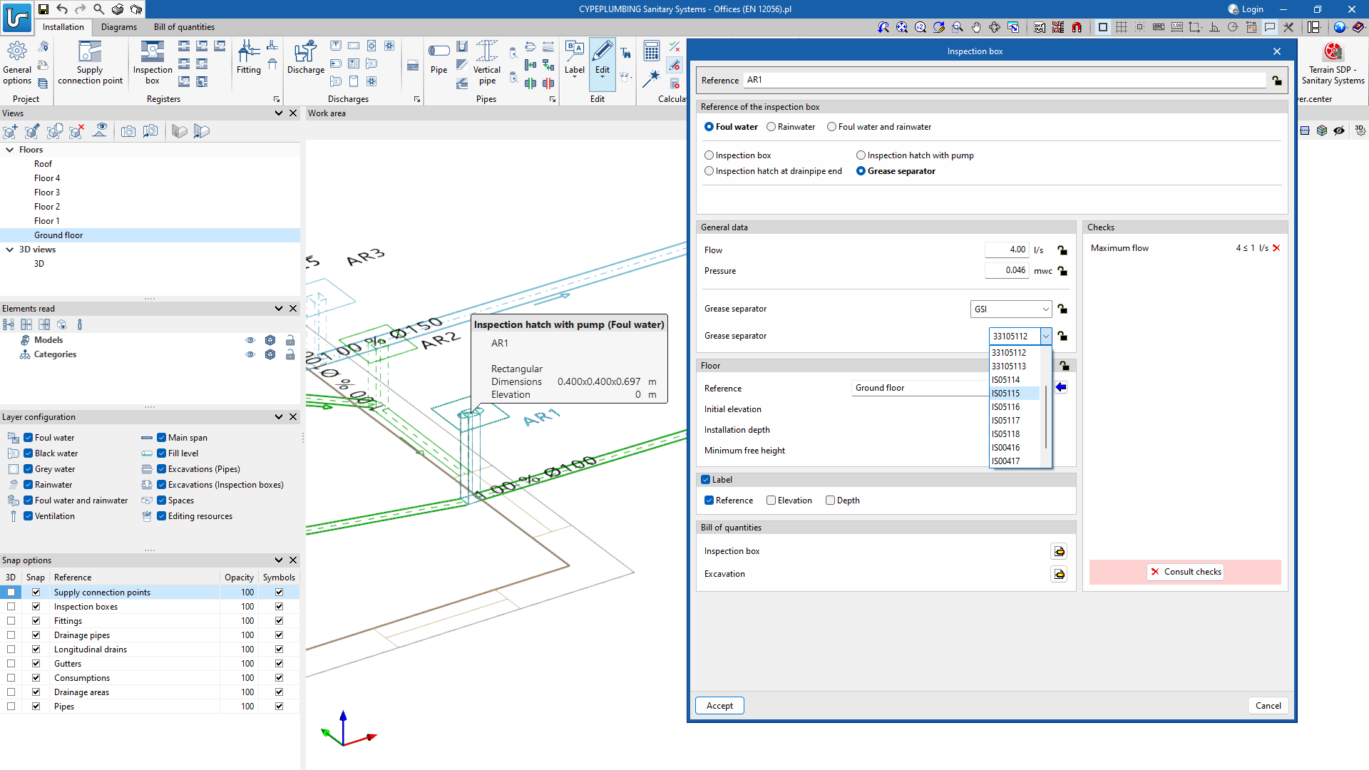
New catalogue of grease and hydrocarbon separators and bio-filtration systems and checks
CYPEPLUMBING Sanitary Systems version 2024.b allows users to enter inspection hatches with grease separators, hydrocarbon separators and biofiltration systems.
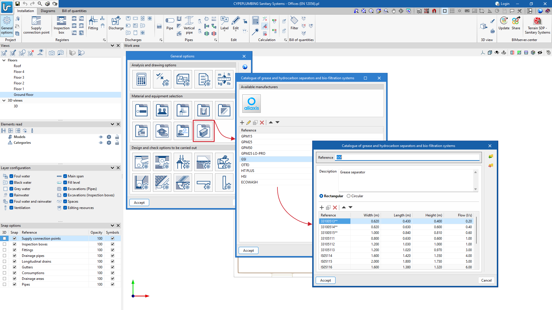
The program also checks these elements. To do this, users must activate the "Grease separator" option ("Technical properties" section) in "Design and check options to be carried out".
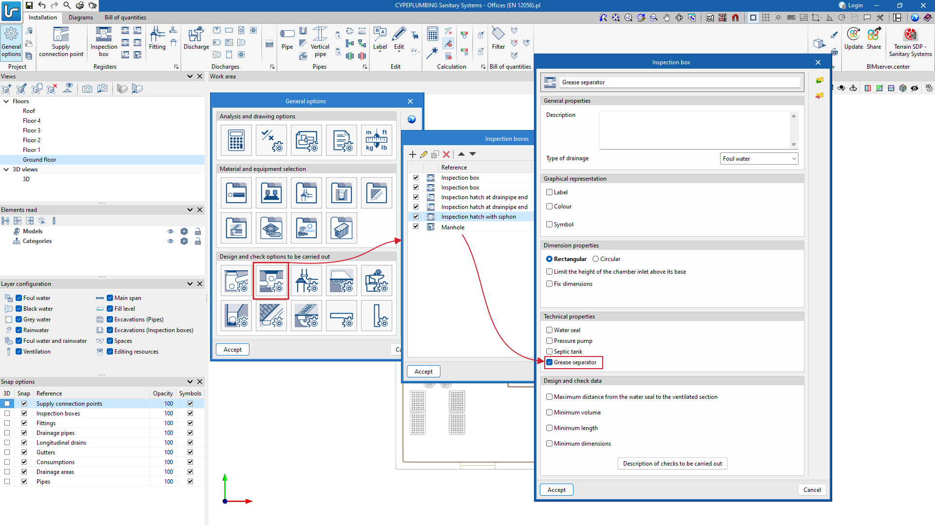
If the above-mentioned option has been activated for a type of inspection hatch, once the grease separator inspection hatch has been entered into the project (the same type can be entered in several places in the system), the program checks that each inspection hatch entered can withstand the calculated flow rate at the point where it was installed.
Portuguese code (SCIE)
As of version 2024.b the Portuguese fire protection design code "Regulamento Técnico de Segurança contra Incêndio em Edifícios (SCIE)" is included. This code will be available as long as CYPEFIRE is installed in Portuguese.
In this first version, the "Utilização-tipo I - Habitacionais" type projects have been included and will be extended with the rest of the projects available in the upcoming versions of the program.
New checks - Fire compartments
For the implementation of the Portuguese code in CYPEFIRE, new checks relating to fire compartments have been developed. These checks can be edited from the general options menu. Among the checks implemented, the following are to be noted:
- Independent levels
Each fire compartment shall be independent. If this check is active, a single fire compartment shall not cover more than 1 level of the building. - Fire resistance of doors
When checking the fire resistance of doors, the Integrity (E) and Insulation (I) capacities have been separated, as the requirements can be independent depending on the spaces to be compartmentalised. - Evacuation
In the evacuation check, the possibility of requiring additional exits from two exits onwards has been introduced, as a certain number of exits may be required depending on occupancy. - Fire protection equipment
New requirements have been included to ensure the presence of fire protection equipment, such as the area above ground level and the area below ground level requirements and the occupancy above ground level and occupancy below ground level requirements.
Establishments
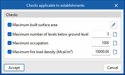
In version 2024.b, establishments have been included. Establishments are building zones that group together the different fire sectors designed and that are under the same ownership.
The following checks can be carried out on establishments:
- Maximum built surface area
- Maximum number of levels below ground level
- Maximum occupancy
- Maximum fire load density
Protected lobbies - Update
The "Protected lobbies" were the only types of compartments that could be assigned directly from the space itself.
From now on (version 2024.b), "Protected lobbies" shall be entered in the same way as all other compartments (fire compartments, risk rooms, stairways, protected zones) to make it easier to use the "Assign" tool.
Also, as of version 2024.b, the "Minimum built surface area" check for "Protected lobbies" has been included.

Risk rooms
As of version 2024.b, users can force the program to set the occupancy of risk rooms to zero. If this is done, all the spaces assigned to risk rooms will not contribute any occupancy to the evacuation, regardless of the occupancy set in them.
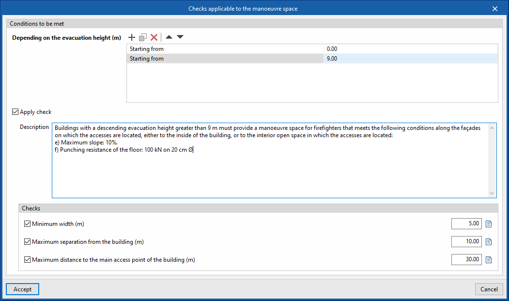
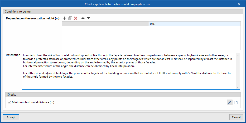
Outdoor propagation and firefighter intervention depending on evacuation height
In order to make CYPEFIRE more versatile, both in the different cases of outdoor propagation (vertical, horizontal and roof-façade) and in firefighter intervention (access road and manoeuvre space), the possibility of requiring more demanding checks as the evacuation height of the building increases has been implemented.
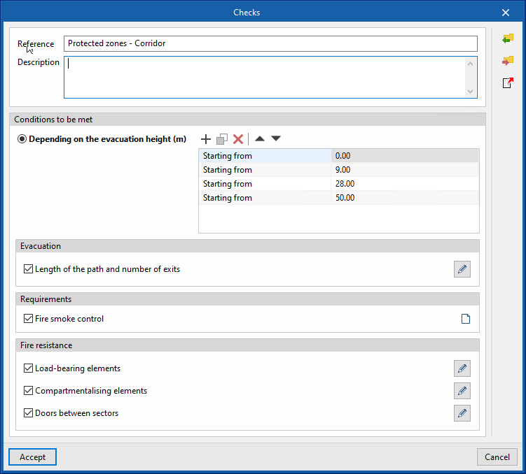
Protected zones
In version 2024.b, protected zones have been included. Protected zones are spaces enclosed by fire-resistant compartmentation elements, designed to allow users to evacuate the building and even to remain inside if necessary.
As well as being enclosed by fire-stopping elements, protected zones may also require the installation of a smoke control system and that the distance to one or more exits does not exceed the maximum permitted distance.
Installation in Polish
As of version 2024.b, CYPEHVAC Radiant Floor can also be installed in Polish. This application can now be installed in the following languages:
- Catalan
- Spanish
- French
- English
- Italian
- Polish
- Portuguese
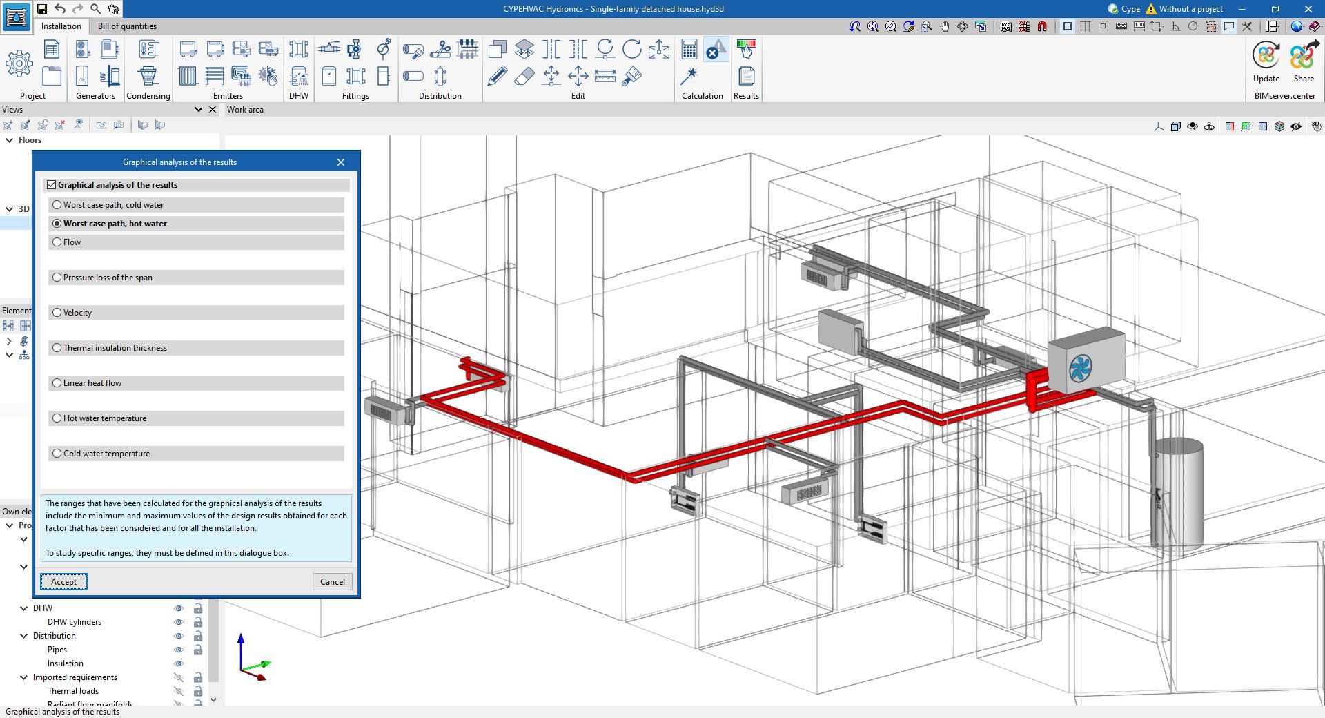
Worst case path in terms of pressure loss
It is now possible to display the worst case path in terms of pressure loss. This path determines the necessary pressure increase in the circulation pump.
To view it, after the "Calculation", select the "Graphical analysis of the results" option in the toolbar and click on the new options in the pop-up dialogue box "Worst case path, cold water" or "Worst case path, hot water". This will cause the pipes that are part of this path in each circuit of the building to be highlighted in blue if they are cold water pipes or in red if they are hot water pipes.
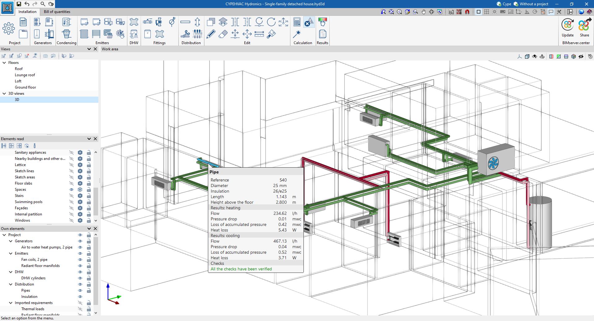
Loss of accumulated pressure
The calculation result of the "Loss of accumulated pressure" of the pipes has been included, both in the results displayed on the screen and in the results report.
After the calculation, when hovering the cursor over a pipe, the pipe’s data is displayed on the screen, and among the data, the result of the "Loss of accumulated pressure" will be shown. This value is the sum of the pressure losses in the elements located between the generator and the indicated pipe, which are both included.
Indoor hydraulic unit
A new unit has been added to the program: the hydraulic indoor unit. This is a commercial unit that brings together all the hydraulic accessories needed in domestic air-source heat pump systems, such as circulating pumps, expansion tanks or buffer tanks, in the same unit. In order to have access to these accessories, simply connect this unit between the air-to-water heat pump and the circuit inside the building.
To place a hydraulic indoor unit in the circuit, click on its icon in the "Fittings" section of the toolbar and place it on the drawing. To define its properties, a unit must be selected from the "Library". Once it has been correctly connected to the circuit, when analysing the system, the hydraulic indoor unit will display the results corresponding to the accessories it contains.
Adding a pipe from an existing pipe
A new tool for drawing pipes in the circuit has been added, which allows the properties of an existing pipe to be copied when adding a new pipe.
To use this tool, click on its icon in the "Distribution" section of the toolbar. First, click on the existing pipe to be copied. The new pipe definition panel will appear, containing the properties of the existing copied pipe. Edit the panel if desired and click on "Accept" to start drawing the pipe.
Installation in Polish
As of version 2024.b, CYPEHVAC can also be installed in Polish. This application can now be installed in the following languages:
- Catalan
- Spanish
- French
- English
- Italian
- Polish
- Portuguese
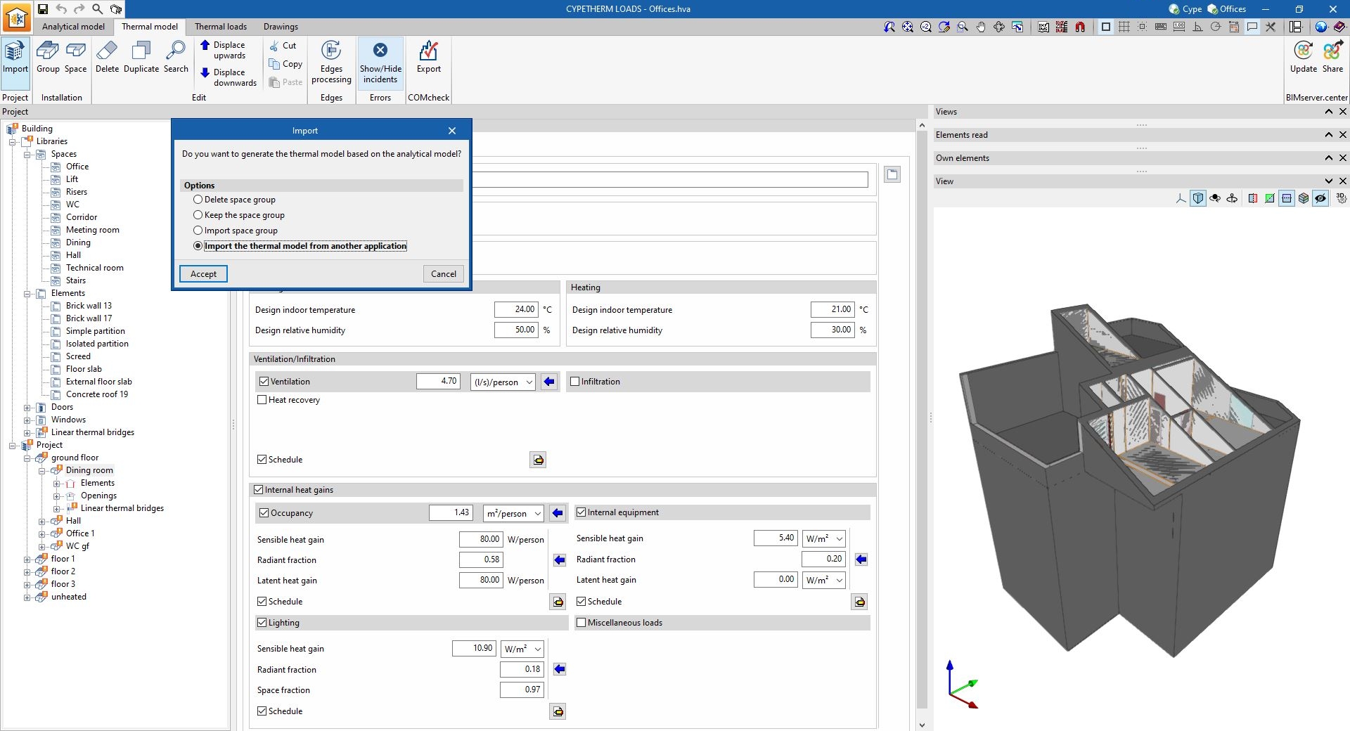
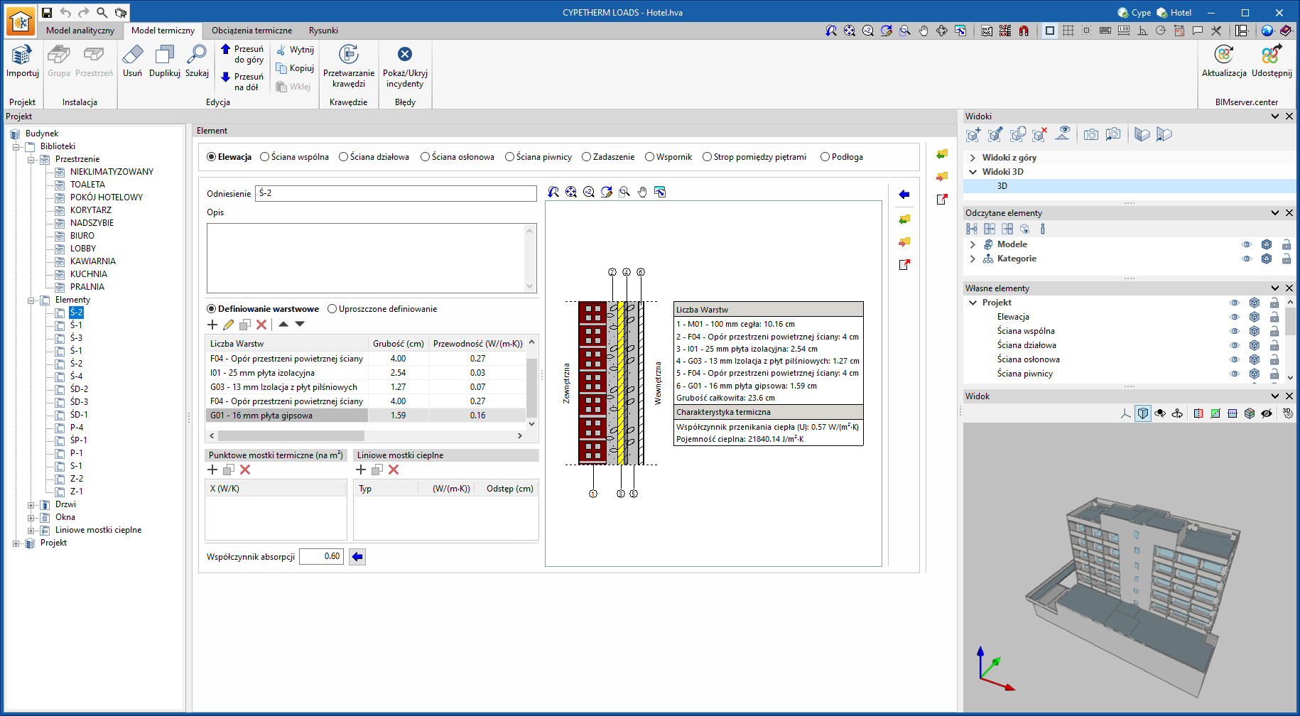
Reading the thermal model
As of version 2024.b, CYPETHERM LOADS can share its thermal models in a BIMserver.center project. Likewise, by selecting contributions from a project containing thermal models, CYPETHERM LOADS can read the information and integrate it into its own thermal model. This feature allows for greater interoperability and efficiency between applications, as it avoids duplications and errors in data entry.
To make use of a thermal model from a BIMserver.center contribution, the "Import the thermal model from another application" option has been added by clicking on the "Import" button in the toolbar corresponding to the "Thermal model" tab in the application. This will be available when contributions containing thermal model definitions have been read. Once the option has been selected, a list with the name of the contributions appears so that users can select one of them to import the thermal model.
Installation in Polish
As of version 2024.b, CYPETHERM LOADS can also be installed in Polish. This application can now be installed in the following languages:
- Catalan
- Spanish
- French
- English
- Italian
- Polish
- Portuguese
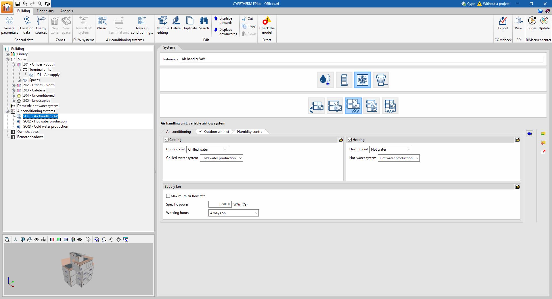
Improved air conditioning system models
The EnergyPlus calculation models used to simulate the air handling units in air-air conditioning systems have been changed. In the previous version (2024.a), this transformation began with the air handling unit of the constant air flow system. In version 2024.b, this change has been completed by also transforming the air handling units of the variable-flow and dual-duct air-air conditioning systems.
In previous versions, a "template" type model available in the calculation engine was used, which presented configuration and combination restrictions with other systems in the same job. With the change of model in version 2024.a and 2024.b, these restrictions have been removed. In addition, the definition interface of these systems has been organised into tabs to make it clearer.
Removal of restrictions on the combination of air conditioning systems
As of version 2024.b, it is possible to combine air-air conditioning systems in the same building. The following exceptions remain:
- No more than one constant performance unit can be defined in the same zone.
- No more than one terminal unit with a ventilation function can be defined in the same zone.
- Combinations of air conditioning terminal units associated with different systems in the same zone are not permitted.
In previous versions, when defining air-air-conditioning systems in the building, there were restrictions that prevented placing more than one terminal unit of any type in the same zone or using more than one water-air conditioning system. As a consequence of the improved models for air-air conditioning systems (also implemented in version 2024.b), these restrictions have been removed.
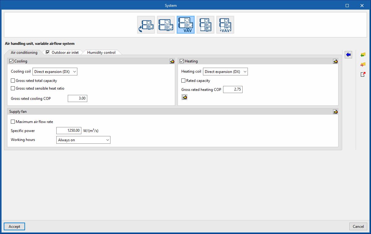
Direct expansion heating coil in the variable air flow air handling unit
In the air handling unit of the variable airflow system, under "Heating" users can now choose the Direct expansion Heating coil. This way, it is possible to simulate a compact rooftop unit with a variable airflow system and with both cooling and heating provided by the compressor.
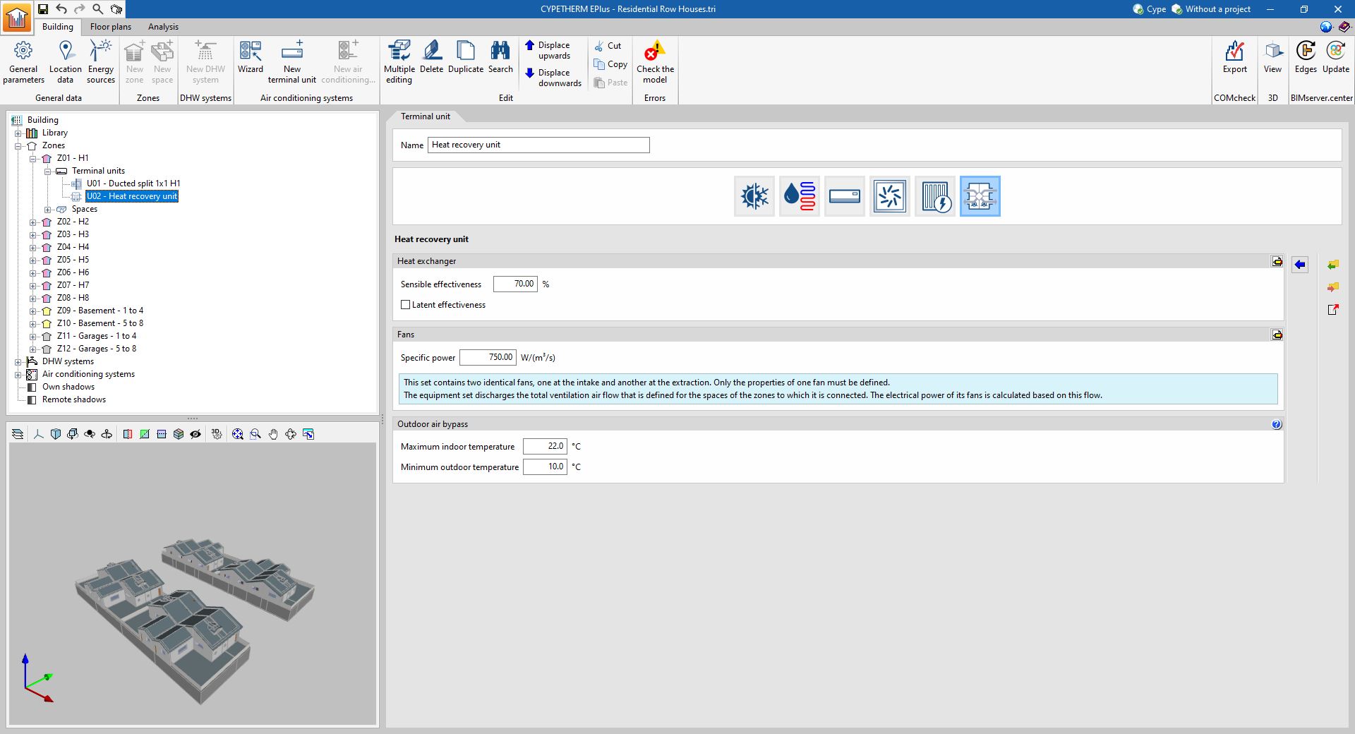
Heat recovery unit with an automatic bypass damper
A new automatic control of the heat recovery unit bypass damper has been included, which allows outside air to pass through when it is convenient to reduce cooling demands.
In previous versions, the bypass damper of the heat recovery unit was activated if the outside air temperature was within the limits selected by the user. In this new version, the damper will be activated automatically whenever the following conditions are met:
- The outside temperature is higher than the "Minimum outside temperature".
- The indoor air temperature is higher than the "Maximum indoor temperature".
- The outside temperature is lower than the inside temperature.
As of version 2024.b, the control of the heat recovery bypass damper is included in the calculation of the building's energy demand, which will lead to a reduction of the calculated cooling demands in buildings with air conditioning systems or ventilation systems that include this unit.
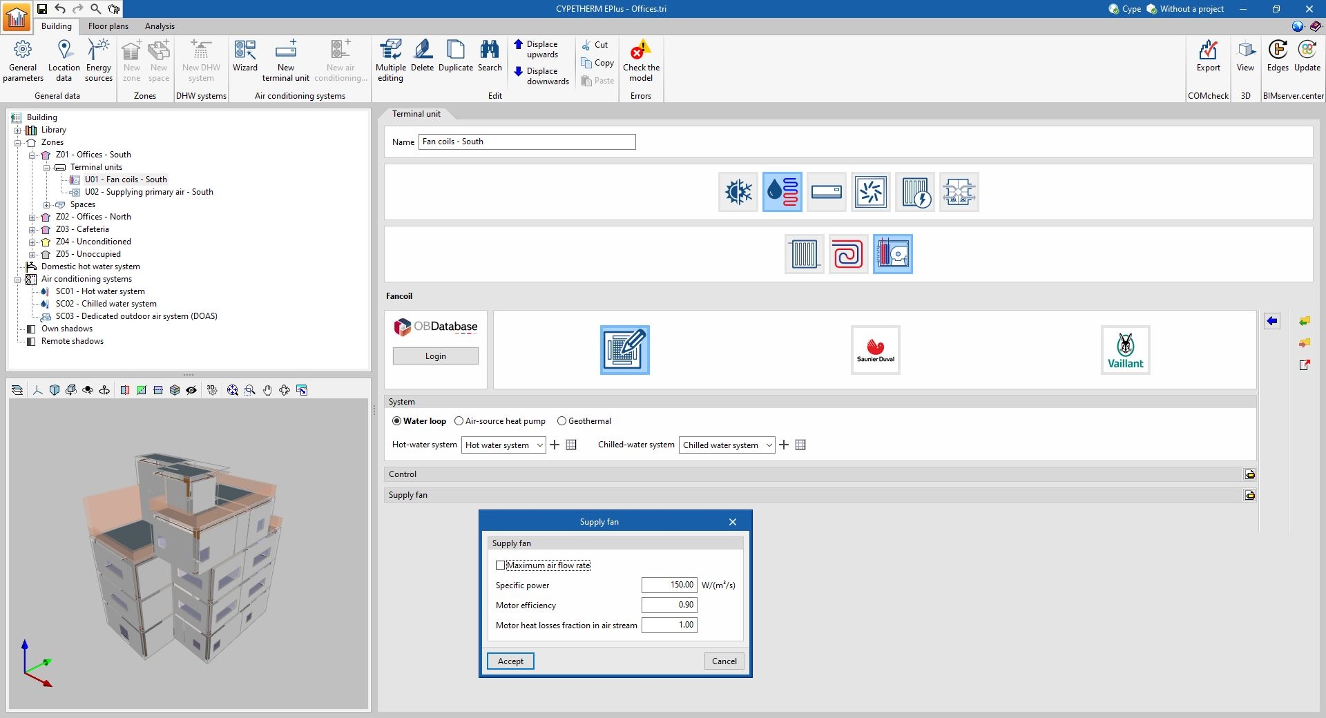
Specific power for fans
As of version 2024.b, the energy consumption of fans included in air conditioning systems is defined by their specific power, i.e. their energy consumption per unit of air flow rate. This value is standard in the documents for these appliances and replaces the previous parameters of "Total pressure rise" and "Total efficiency". The program calculates these parameters, which are the input for the calculation engine, on the basis of the new "Specific power".
Available at BIMserver.center
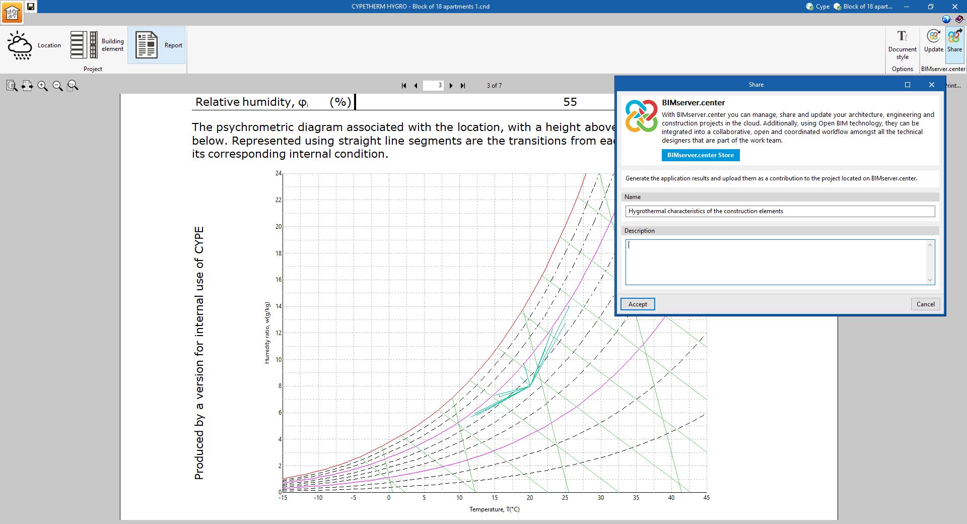
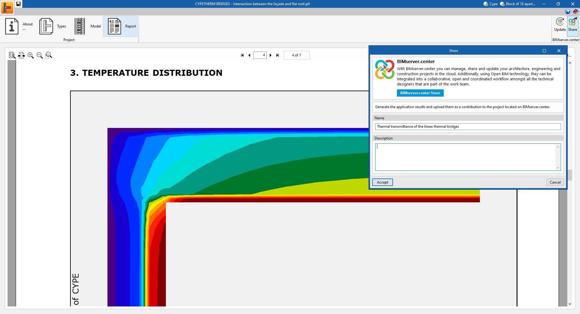
As of version 2024.b, the CYPETHERM HYGRO and CYPETHERM BRIDGES applications are now available for download from the BIMserver.center platform. In previous versions, they were only available in the classic menu of CYPE programs.
Connection with the BIMserver.center platform
As of version 2024.b, the CYPETHERM HYGRO and CYPETHERM BRIDGES applications can access the collaborative work platform BIMserver.center. A link can now be established with a BIMserver.center project and the "Report" generated by each application can be shared. For this purpose, the "BIMserver.center" group of options with the "Update" and "Share" buttons has been added to the toolbar of CYPETHERM HYGRO and CYPETHERM BRIDGES.
Reading construction systems from the BIMserver.center project
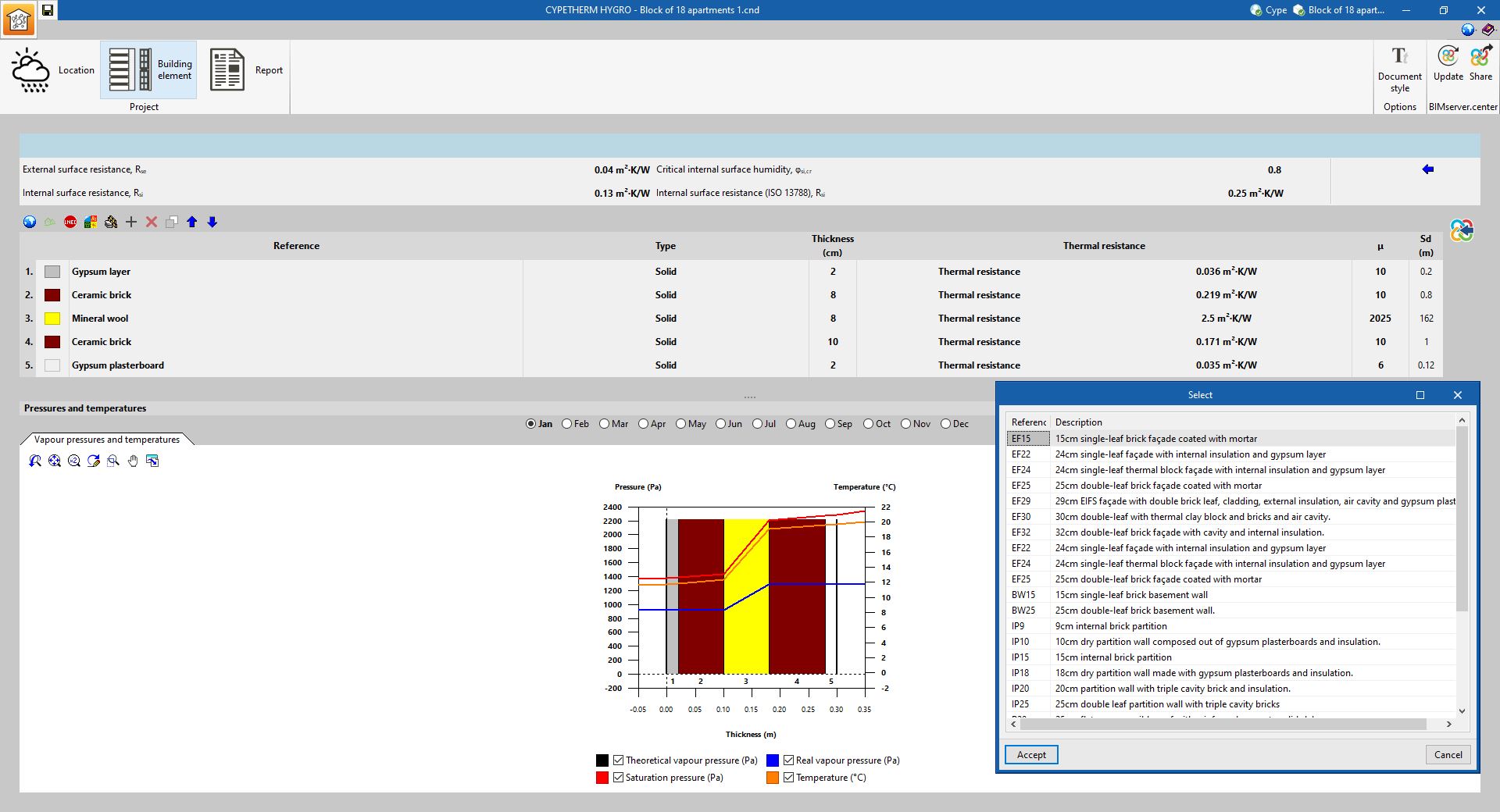
As of version 2024.b, CYPETHERM HYGRO can read the construction systems contained in the project from BIMserver.center. These can now be defined and shared in the project via the CYPE Construction Systems application.
To use the properties of a construction system from the project, a new button has been added to the "Building element" section in CYPETHERM HYGRO. When clicking on it, a list of all available construction systems from the project contributions is displayed. Once the element has been selected, the material layers and their properties are added automatically. This way, their internal surface resistance factor and interstitial condensation can be easily calculated.
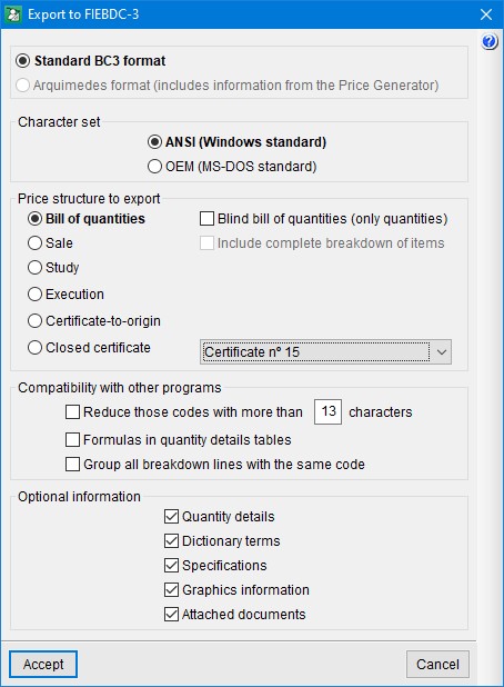
Improvements in the export to FIEBDC-3
The export to FIEBDC-3 format has been improved. Now, when exporting to this format, users must select the export type:
- Standard BC3 format
This option must be selected if the BC3 file is to be imported from any application that supports the FIEBDC-3 standard. - Arquimedes format
This option can be selected if the BC3 file is to be imported by Arquimedes. With this option, information from CYPE's construction cost database "Generador de precios" is included in the generated BC3 file. The information from the "Generador de precios" is included in the "Technical information" section of the FIEBDC-3 standard. This section allows the standard FIEBDC-3 format to be extended and, in this case, with the additional information relating to the construction cost database used that other applications cannot interpret.
Arquimedes may import the BC3 file generated by both types of export, but if importing the BC3 file generated with the "Arquimedes format" option, it will import the information from the "Generador de precios" if the job with which the export is generated has used this cost database.
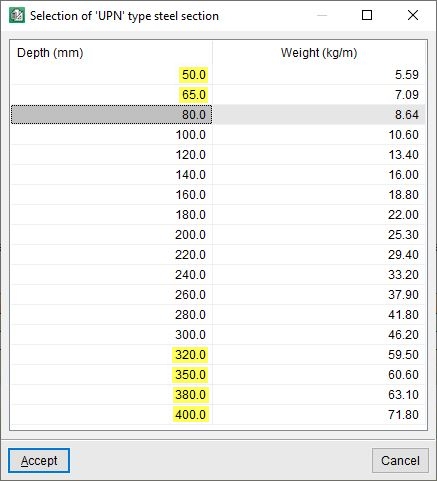
Quantities of UPN steel sections
When a quantities sub-table of the type "Weight of UPN type steel section" is added, the program will ask for the value of the edge (E), particularly when entering the values of its formula.
In Arquimedes version 2024.b the UPN section table has been extended with six new values for edges:
- 50 mm
- 65 mm
- 320 mm
- 350 mm
- 380 mm
- 400 mm
Information in the status bar
Since version 2023.g, Open BIM Quantities includes a status bar at the bottom of the main window. In addition to displaying contextual information about what is being carried out in the application, the status bar indicated the reference of the active sets of measurement rules. In version 2024.b, the status bar has been improved and now also displays the following information:
- Active filter reference.
- Active certificate reference.
- Reference of the active cost database.
Items with a negative quantity
In previous versions, when selecting "Update the quantities" and applying the active "Set of measurement rules" on the model, items with a negative quantity value were not taken into account when generating the quantities. As of version 2024.b, Open BIM Quantities can generate items with a negative quantity and use them for indicating deductions or allowances in the bill of quantities, among other functions.
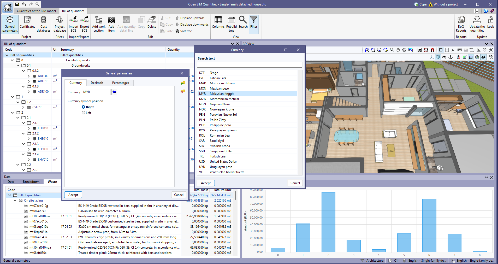
New currency codes
In the help tool for filling in the currency code, within the general parameters of the project, the following references from ISO 4217 have been added:
- EGP. Egyptian pound
- KZT. Tengue
- MYR. Malaysian ringgit
- PHP. Philippine peso
- SAR. Saudi riyal
Improvements in the checking of the "Maximum buildable area, depending on use"
To make it easier for users to view the "Maximum buildable area, depending on use", two improvements have been implemented in its check:
- New arrangement in the tree structure by floor and type
In previous versions, each computable built area was shown separately in a table. This made it more difficult to review the check due to the large number of areas that a building could contain.
As of version 2024.b of the program, the table of computable built areas is arranged in a tree structure that shows which floors have the types of computable built areas that exist on that floor. This makes it much easier to check by floor and by type of area. - Highlighting computable built areas according to type
In previous versions of the program, the check would highlight all areas in green if they met the check and in red if they did not.
The purpose of the check, as well as finding out whether an area is compliant or not, is to quickly and easily view the computable built areas, depending on use. For this purpose, as of version 2024.b, the lighting of the area is carried out according to the colour assigned to the type.
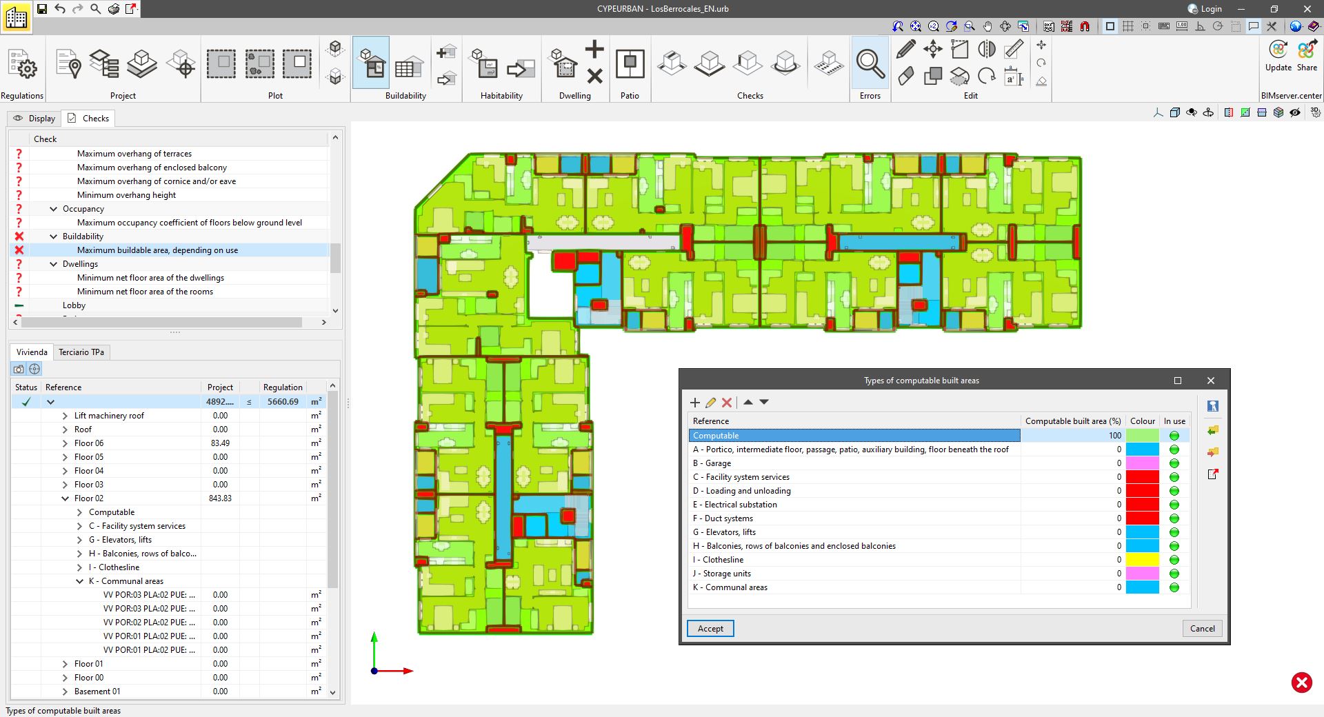
Both improvements allow for a highly intuitive and fast viewing of all types of computable built areas that exist on a floor.