
Options in the "3D view" group
The program allows for a detailed three-dimensional view of the model or parts of the model in a separate window. To access this, open the "Project" tab at the top of the interface and use the options available in the "3D View" panel.

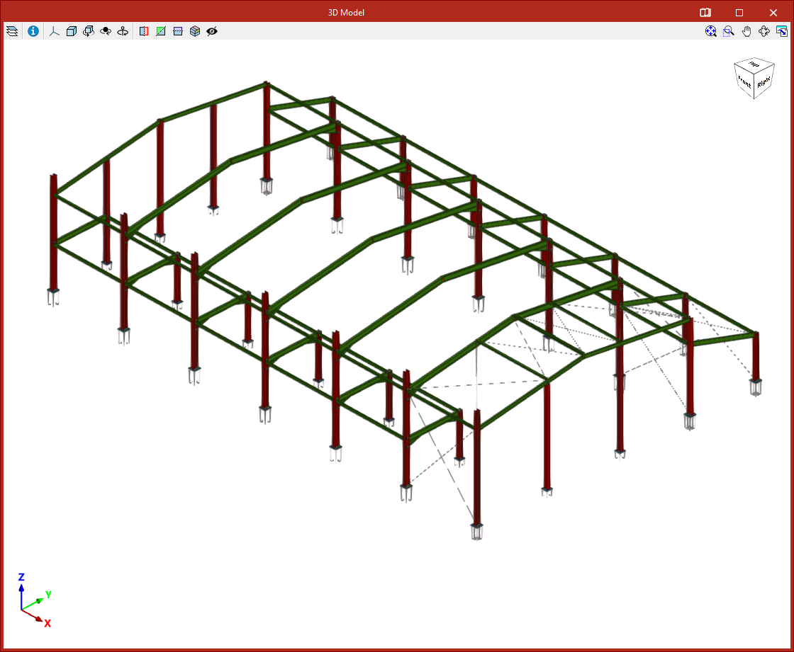
3D view of the complete structure
The "Complete structure" option generates a 3D view that includes all elements of the project with their actual shapes and dimensions.
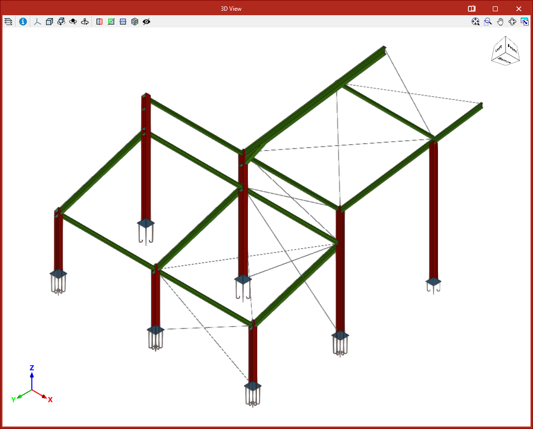
3D view of the active window
Using "Active window" generates a 3D view that includes only the elements contained in the window that is active at the time the option is selected.
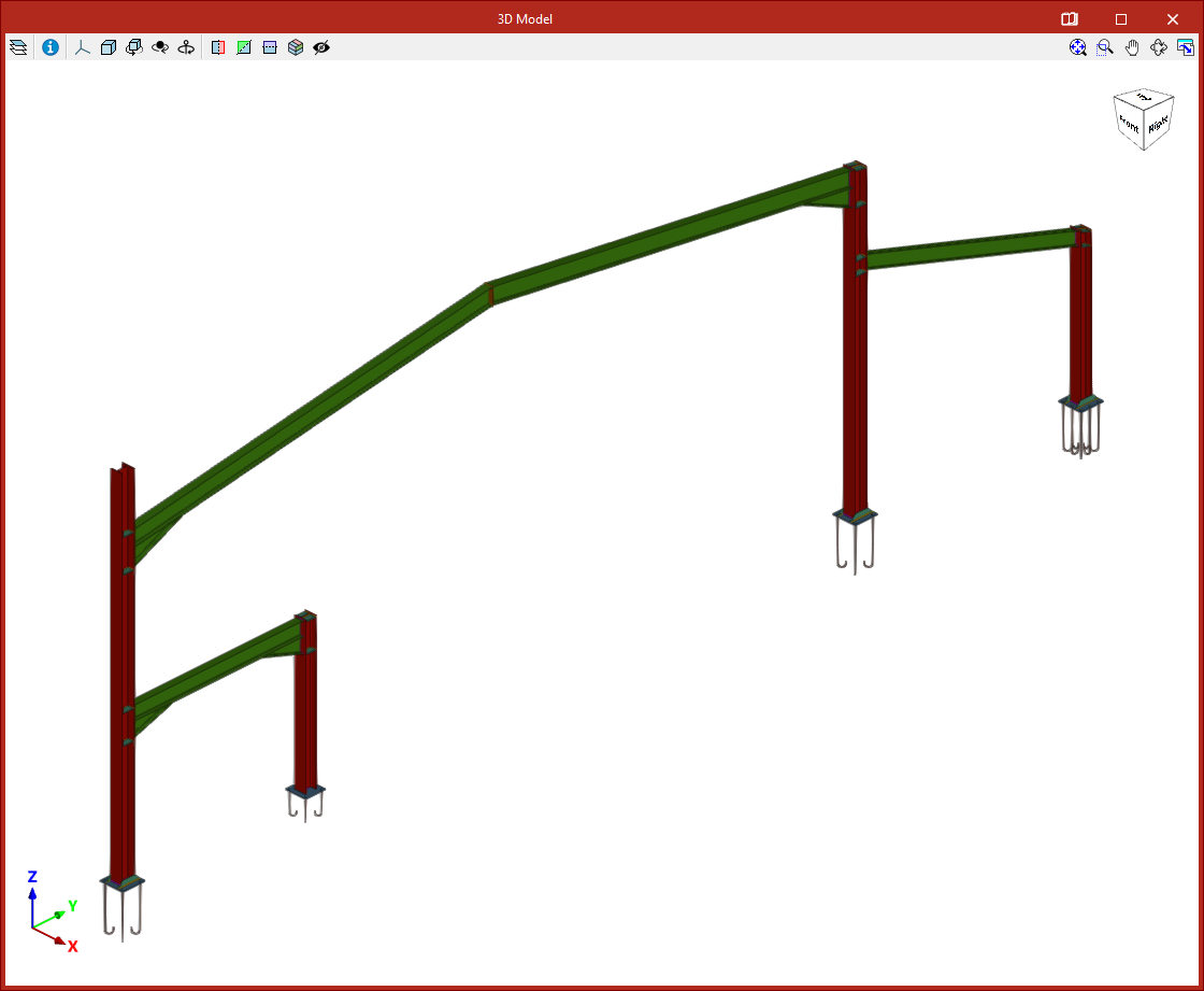
3D view of a selection of elements
The "Selection of elements" option generates a 3D view that includes only the selected elements.
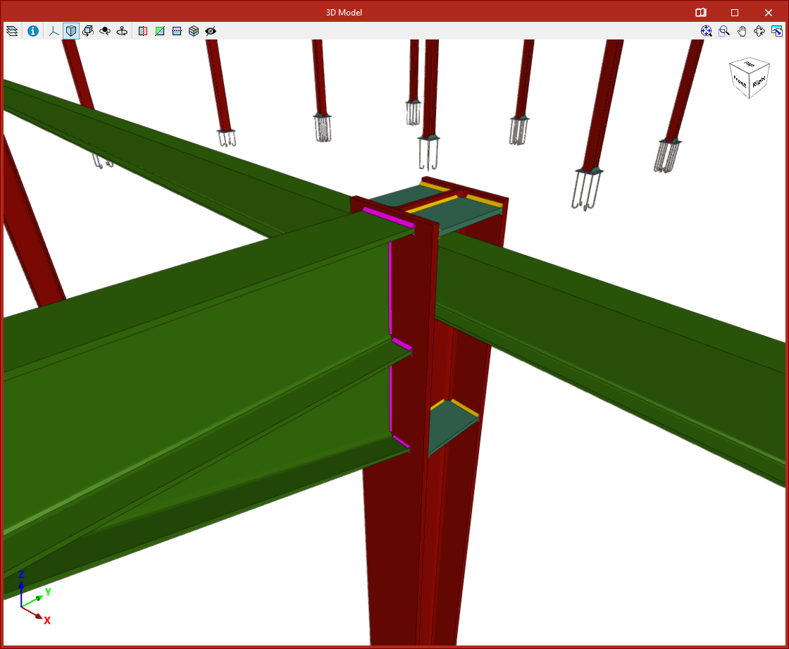
Displaying connections in the 3D view
Clicking the last button enables you to "Draw the 3D view with the applied connections". This way, the analysed connections are shown in detail in the 3D view obtained from any of the other options.
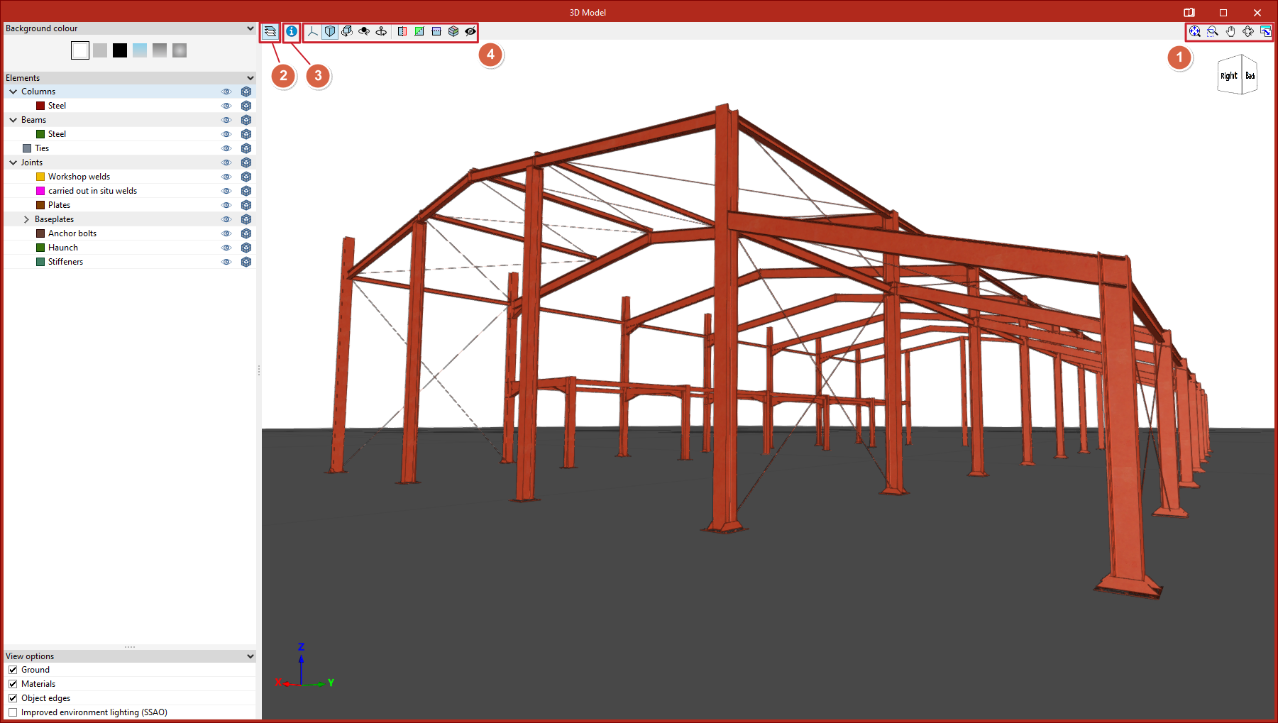
"3D model" window
Selecting any of the above options opens a window displaying the "3D model".
Orbiting, zooming, and framing
The program offers the following controls:
- Orbit the model by holding the left or right mouse button while moving the mouse.
- Zoom using the mouse wheel.
- Change framing by holding and dragging with the mouse wheel or middle button.
- Double-clicking the mouse wheel or middle button centres the view on the entire drawing.
These actions can also be performed using the options in the upper right corner (1), which are similar to those found in the program’s main interface. From here, you can view the entire drawing in "Complete window", "Highlight zoom", "Move image", or perform a "3D orbit". You can also "Print" the current view in various file formats.
Side panel options
From the "Elements" option (2) in the upper left, a side panel opens where the visibility of elements in the view is managed.
- First, you can change the "Background colour".
- In the next section, "Elements", you can toggle the visibility of different groups of structural elements, as well as adjust their opacity and transparency.
- At the bottom, other "Display options" can be activated, such as "Ground", "Material textures", "Object edges", and "Improved environment lighting (SSAO)".
Checking element information
By clicking on "Consult the information of the element" (3), you can double-click on any element to obtain information about its properties.
Model visibility control tools
At the top of the viewer (4), a series of tools are available to control model visibility:
- Use "Projection" to access preset views of the model, such as axonometric, elevation, or plan views.
- Clicking the "Type of projection" option switches between axonometric and perspective projections.
Further tools allow you to rotate the model:
- First, "Rotate about the vertical axis" continuously rotates objects in the view.
- Then, activating "Rotate around a point" rotates the scene around an object located under the mouse cursor.
- "Rotation about the camera" rotates the scene around the vertical axis at the camera's position.
Next, there are options to create a "Perpendicular section" to any of the three global axes: X, Y, or Z. By clicking and dragging the arrow and arc symbols that appear, you can move or rotate the section plane. Double-clicking the arrow reverses the direction of the cut.
You can also define a "Clipping volume" using six cutting planes generated from the geometric envelope of the scene content.
Finally, the last option allows you to "Show/Hide section planes".