Analysing the structure, checking and designing sections
The analysis, checking, and automatic design of the sections and connections in the structure is carried out using the "Analyse" option, available in the "Stress/Strain" group in the top toolbar, under the "Analysis" tab (in the "Structure" tab):

Analyse
Clicking this option opens the "Analysis" window, where various analysis parameters can be configured under the following sections:
Analysis to be carried out
This section appears if nonlinear combinations have been defined and/or nonlinear elements have been inserted in the model. In that case, the following analyses can be activated. One or both of the following must be selected:
- Linear stress/strain analysis
Performs a linear analysis of the structure. Nonlinear elements are treated as linear for this analysis. - Nonlinear stress/strain analysis
Performs a nonlinear analysis of the structure.
A nonlinear analysis can be carried out without having defined nonlinear combinations in advance. In this case, the program will determine which combinations need to be analysed based on the results of the linear analysis, displaying the message:
"The program will automatically generate nonlinear combinations after the linear analysis."
If nonlinear combinations have been defined, a checkbox will appear allowing you to "Update non-linear combinations after the linear analysis".
The checking of the bars is performed using the results available after the analysis. If both linear and nonlinear results exist, the program will combine them according to the types of combinations assigned to each element.
If no nonlinear combinations are defined and no nonlinear elements are inserted into the model, this section will not appear, and the program will default to a linear stress/strain analysis.

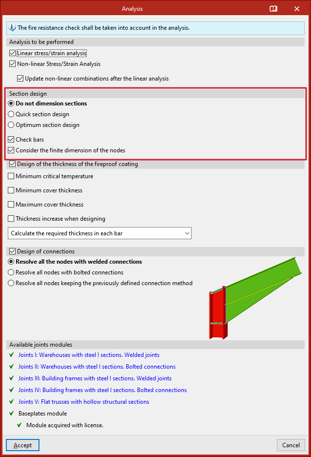
Section design
In the "Section design" section, the program's behaviour is specified in case any bars do not comply.
- If "Do not dimension sections" is selected, the program will analyse the structure but will not make any changes to the input sections.
- Selecting "Quick section design" instructs the program to check each bar against the internal forces obtained during analysis. If a section fails, it is replaced with the next larger section from the same series that passes all checks. A new analysis is then performed. This process is repeated iteratively until all bars comply or the largest section in the series is reached.
- With "Optimum section design", any failing section is replaced with the next in the series (regardless of whether it complies or not), followed by a new analysis. This method is slower but reduces the risk of assigning excessively large sections.
For either method, you may specify whether the design should be carried out "Using sections of the series greater than the current section" or "Using all the sections of the series".
If the "Check bars" box is checked, the program will verify compliance of all bars. If unchecked, only internal forces and displacements will be analysed.
The "Consider the finite dimension of the nodes" option allows the program to automatically adjust bar lengths by subtracting connection dimensions at nodes. This should be enabled if an analysis is going to be carried out on the connections in the structure.
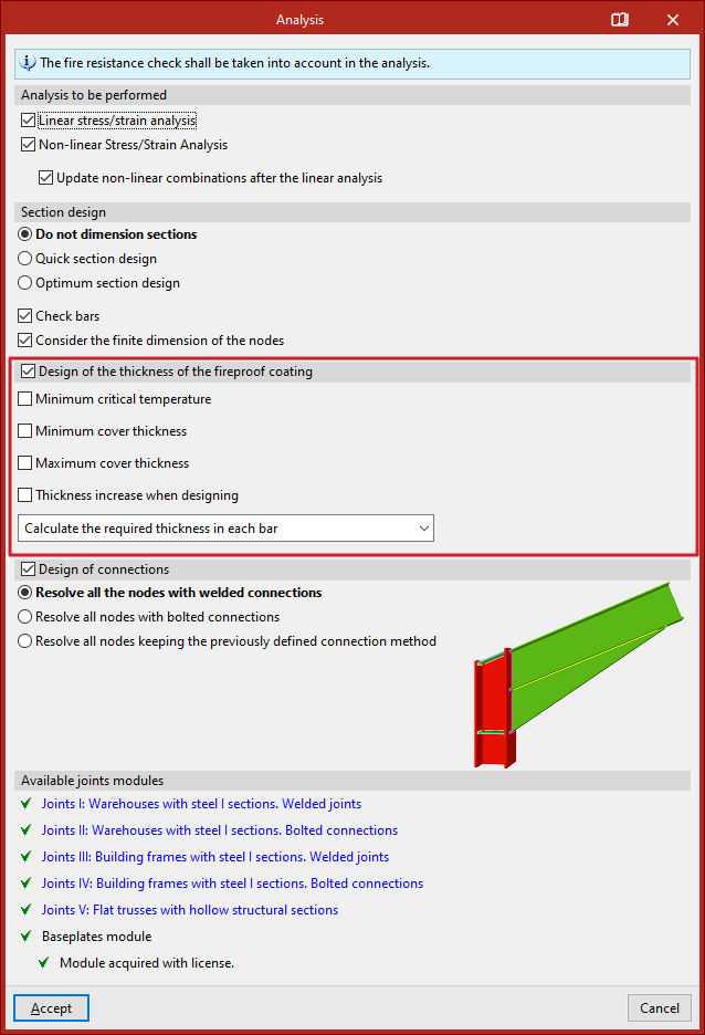
Design of the thickness of the fireproof coating
If fire resistance checking has been enabled in the "General data" and a specific fire protection coating has been selected, the "Design of the thickness of the fireproof coating" can be carried out for the bars. The following options are available:
- Minimum critical temperature
Defines the minimum critical temperature for sizing the fire protection thickness. - Minimum cover thickness
Sets a minimum value for the coating thickness. - Maximum cover thickness
Defines a maximum coating thickness. - Thickness increment when designing
- Sets the increment used by the program during the design process.
- Cover unification
In this dropdown, you select how the calculated cover thickness is applied:- Calculate the required thickness in each bar
Assigns the exact required thickness to each individual bar. - Match the thickness of all the bars
All bars will receive the thickness required by the most unfavourable bar. - Match the thickness of all the bars with the same section
Bars with the same cross-section will receive the thickness required by the most unfavourable among them. - Match the thickness of the bars belonging to the same the group
- Bars in the same group will receive the thickness required by the most unfavourable bar in the group.
- Calculate the required thickness in each bar
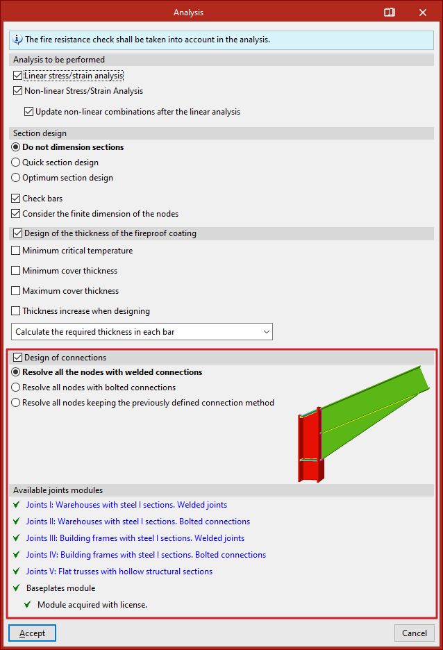
Design of connections
If connections have been generated, the "Design of connections" option can be activated to include them in the analysis process.
In the selector, choose whether to "Resolve all the nodes with welded connections", "Resolve all nodes with bolted connections", in which case you can also enable the "Use prestressed bolts" checkbox or "Resolve all nodes maintaining the previously defined joint method".
Available joints modules
In the last section, the program displays the "Available joint modules" included in the license.
You can click any of the links to consult the set of joints that can be designed within each module.
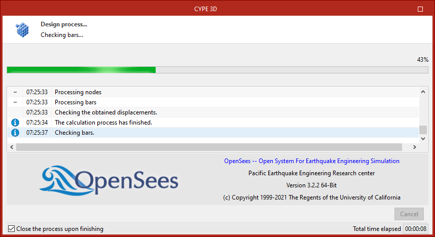
Design process
After clicking "Accept", the program launches the analysis window, which displays the different stages of the process, including component discretisation, equation solving, bar checking, and connection design.
It also displays information about the OpenSees engine (Open System for Earthquake Engineering Simulation) used during nonlinear analysis, or—if not performing a nonlinear analysis—the number of "Available processors" and "Used processors". In some stages, the program can use additional processors if a multiprocessor license is available.At the bottom of the window, you'll find the "Close" option and a checkbox "Close the progress upon finishing", which closes the analysis window automatically when the process is finished. The "Total time elapsed" since the start of the analysis is also displayed.
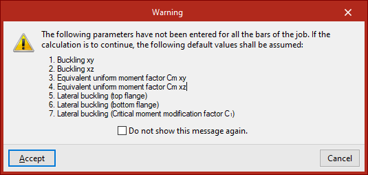
| Note: |
|---|
| Before launching the analysis, the program will display a "Warning" listing any missing parameters (e.g. buckling or lateral buckling data) for the bars. If this warning is accepted, the program will proceed using default values. |
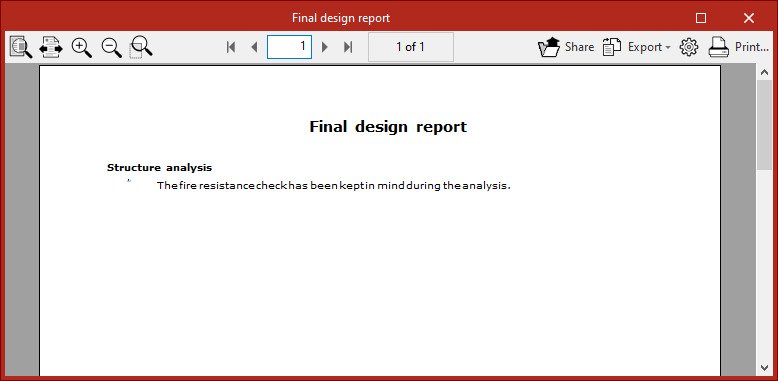
Final design report
At the end of the analysis process, the program displays the "Final design report" with any issues detected.
| Note: |
|---|
| You can select the "Issues" option in the toolbar under the "Analysis" tab to visually locate problems in the model. Hovering the mouse cursor over each issue will show a message describing the problem. |