Description of bar layout
The description of the bar layout is carried out using the following tool, available in the "Bars" group on the top toolbar, within the "Geometry" tab (under the "Structure" section).

Layout
After clicking on the "Layout" option, bars are selected individually with the left mouse button or by drawing a selection area.
Then, right-click. In the window that appears, the layout of the bar’s cross-section can be defined in relation to the line entered in the model.
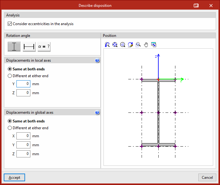
In the first section, "Analysis", you can specify whether to "Consider eccentricities in the analysis" by ticking the corresponding checkbox. If this option is not enabled, the bar will be considered centred in the design model.
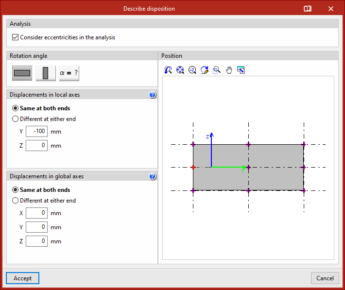
Next, the "Rotation angle" of the section is defined. It can be "0" degrees, "90" degrees, or a "Rotation angle" defined by the user with any value.
In the viewer on the right-hand side, the "Position" of the cross-section is shown relative to the local Y and Z coordinate axes, displayed in green and blue, respectively.
The reference point is marked with a red cross and is positioned at the centre of the section by default. You can click on the crosses located at the edges or corners of the section to modify the position of the reference point.On the left, under the section "Displacements in local axes", the displacement values of the section's reference point are entered relative to the coordinate system defined by the local axes of the element.
- If "Same at both ends" is selected, the displacement value can be entered for the local "Y" or "Z" axes. Doing so will display the position change of the section relative to the local coordinate axes in the viewer on the right.
- If "Different at either end" is selected, displacement values must be entered for both the "Start" and "End" of the member. In this case, the cross-section of the member is shown at both points in the right-hand viewer.
Next, under the section "Displacements in global axes", the "X", "Y", and "Z" coordinates of the ends of the element are specified in relation to its definition nodes within the global coordinate system.
Again, displacements can be "Same at both ends" or "Different at either end".
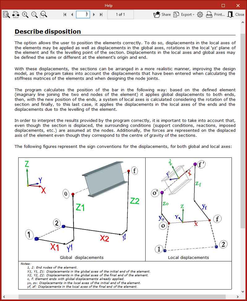
For more information about bar positioning and the sign conventions for global and local displacements, you can click on the corresponding button in the title bar of this window to consult the help provided by the program.
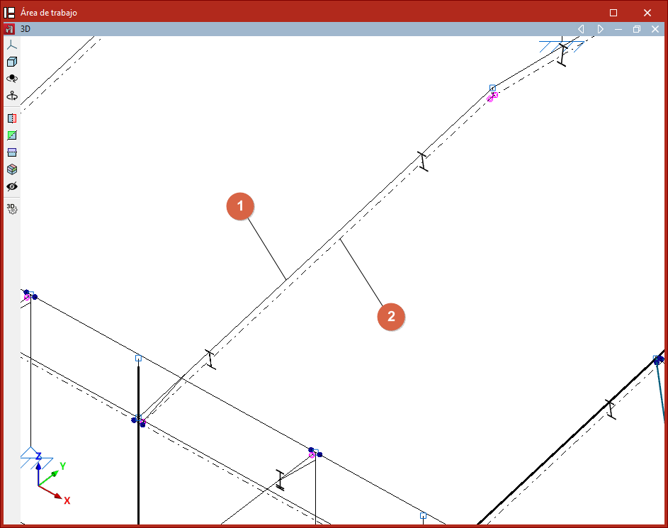
After modifying the bar layout in the workspace, the line entered in the model is shown as a continuous line (1), while the actual position of the bar's section axis is represented as a dashed or dash-dot line (2).