Editing the buckling parameters of the bars
The buckling parameters for the bars are defined using the following option, which is available in the "Bars" group on the top toolbar, within the "Properties" tab (under the "Structure" section).

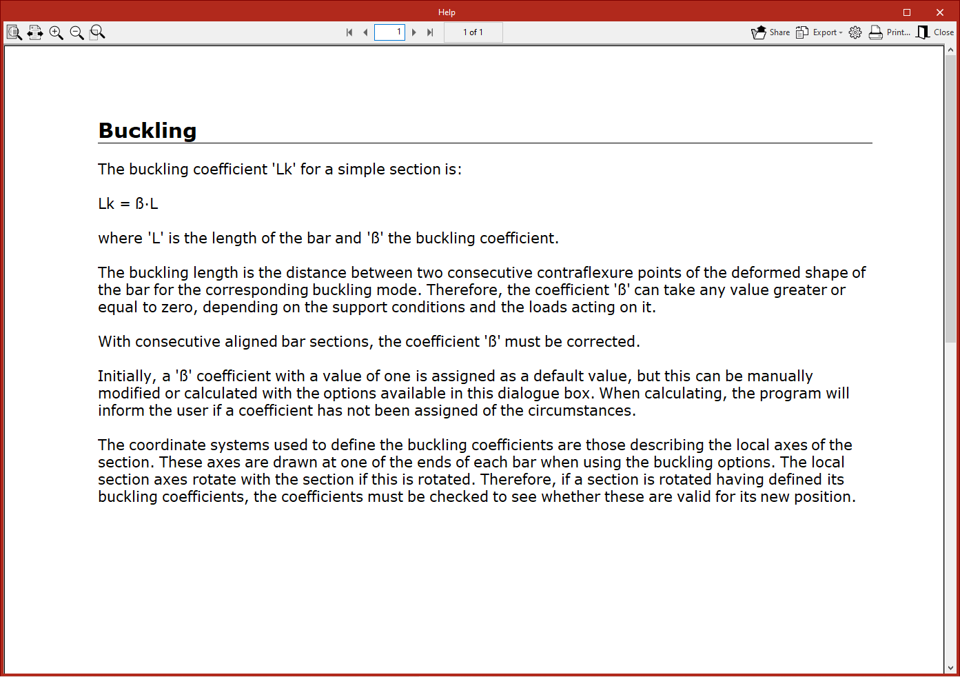
Buckling
The "Buckling" option allows you to edit the parameters relating to the buckling of the bars.
After clicking on the option, select each bar by clicking on them one by one, or highlight a capture area. Then, right-click.
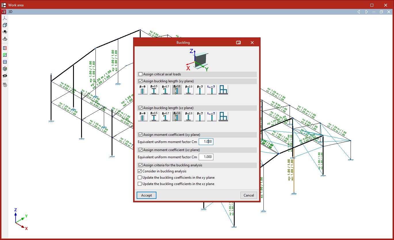
In the window that appears, you can define the buckling parameters in two different ways:
- If the "Assign critical axial loads" checkbox remains unchecked, the buckling lengths (or buckling coefficients) of the bar are entered, along with the moment coefficients in the local XY and XZ planes. In this case, the critical axes of the bar are calculated automatically by the program.
- If the "Assign critical axial loads" checkbox is checked, you can enter the values for the critical buckling axes, as well as the moment coefficients in the local XY and XZ planes.
To make it easier to identify the buckling planes, the diagram above shows the local coordinate axes of the section, using the same colour coding as in the model.
Assigning critical axial loads
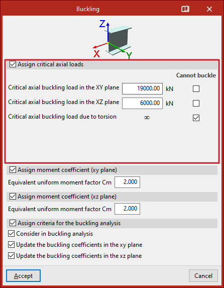
To assign critical axial loads, tick the "Assign critical axial loads" box.
This section allows you to manually enter the values for the critical axial buckling loads as an alternative to the buckling lengths:
- Critical axial buckling load in the XY plane
- Critical axial buckling load in the XZ plane
- Critical axial buckling load due to torsion
The "Cannot buckle" checkbox can be ticked in any section. In this case, an infinite critical axis is assumed.
Assigning buckling lengths or buckling coefficients
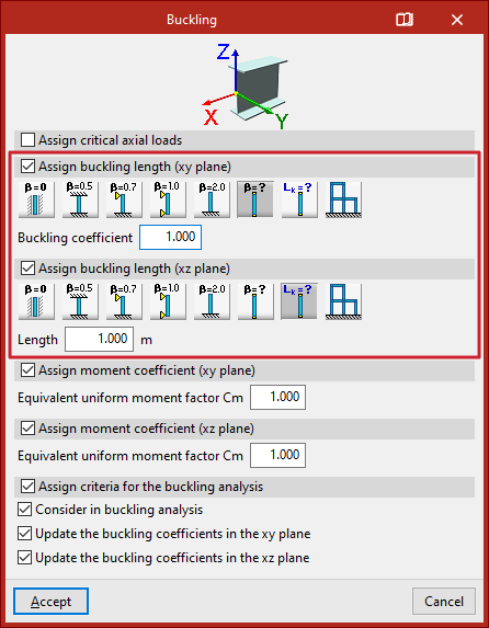
If you choose to assign buckling lengths or buckling coefficients, the "Assign critical axial loads" checkbox is deselected.
The program then allows you to assign buckling lengths or buckling coefficients to each local plane of the section by ticking the relevant boxes (“Assign buckling length (xy plane)” and “Assign buckling length (xy plane)”).
If you choose to define the buckling coefficient (beta), this value will be multiplied by the length of the bar from node to node to obtain the buckling length.
The available options include the following:
- Do not take buckling into account
In this case, the program uses a default value of 0 for the buckling coefficient. - Beam fixed at both ends
A buckling coefficient of 0.5 is assumed. - Bar, simply supported at one end and fixed at the other
A buckling coefficient of 0.7 is used. - Simply supported bar
A buckling coefficient of 1 is assumed. This is the default selection made by the program. - Cantilever bar
A buckling coefficient of 2 is assumed. - Other buckling coefficient values
This option allows you to manually enter the "Buckling coefficient" in the field below, rather than using one of the predefined values. - Assign buckling length
This option allows you to enter the buckling length directly, rather than using a coefficient to multiply the bar length. To do this, select the relevant option and enter the "Length" value in the units of measurement defined in the project. The buckling length corresponds to the distance between two consecutive inflection points in the bar’s deformed shape. - Approximate calculation of buckling lengths
This option allows you to perform an approximate calculation of buckling lengths, specifying whether the structure is a "Sway frame" or "Non-sway frame" type. The validity of this approximate analysis is limited to substantially orthogonal structures. There are other conditions and limitations for this analysis, which can be found in the help text that appears when you hover the pointer over the option.
| Note: |
|---|
| The approximate analysis of buckling lengths is based on commonly accepted formulas whose validity is limited to substantially orthogonal structures. The user must specify, at their discretion, whether the structure is translational or intranslational. Furthermore, the following assumptions are accepted - The supports buckle simultaneously - Elastic shortening of the supports is neglected - The beams behave elastically and are rigidly connected to the supports - The stiffness of the beams is not altered by normal forces. There are a number of limitations regarding the validity of the buckling coefficient results provided by this method, which must be taken into account - The presence of intermediate nodes in continuous bars, to which no other bars are connected, invalidates the method; therefore, in such cases, the necessary manual corrections must be made. - The method requires the structure to be classified as translational or intranslational; care must therefore be taken with this definition. - If the structure entered is a plane frame, the values obtained are valid in its plane but may not be valid in the perpendicular plane (for example, because bracing elements exist in reality that are not defined in the calculated structure). |
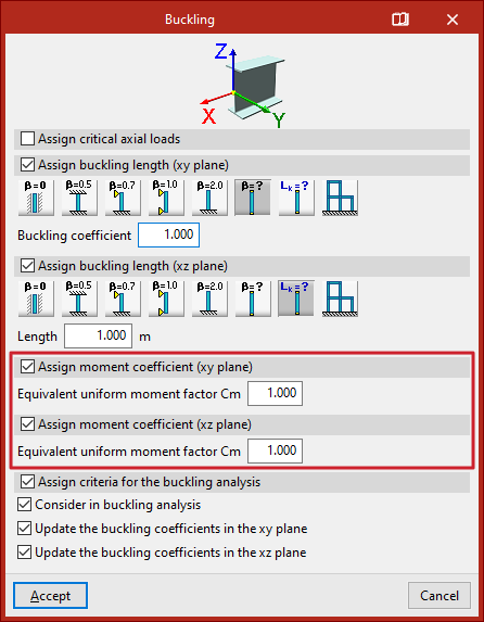
Assignment of moment coefficients
You can then enter the moment coefficients in the local XY and XZ planes.
To do this, tick the boxes "Assign moment coefficient (xy plane)" and/or "Assign moment coefficient (xz plane)", then enter the "Equivalent uniform moment factor Cm" for each plane.
Each standard provides values for these coefficients based on the different bending moment distributions between bracing points.
By default, the program uses coefficients equal to one.
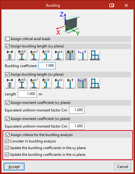
Assignment of criteria for buckling analysis
The "Assign criteria for the buckling analysis" section relates to the linear buckling analysis performed by the program using the options in the "Buckling" group on the "Analysis" tab. This analysis allows the buckling coefficients of the bars to be obtained and updated automatically.
This section contains three options:
- Include in buckling analysis
By ticking or unticking this box, you can specify whether or not the bar is included in the buckling analysis. - Enable updating of buckling coefficients in the XY
plane
Ticking this box allows the program to update the bars' buckling coefficient in the local XY buckling plane. - Enable updating of buckling coefficients in the XZ
plane
Ticking this box allows the program to update the bar’s buckling coefficient in the local XZ buckling plane.
Updating the buckling coefficients requires a buckling analysis to be carried out. When assigning buckling coefficients to the bars, the program will automatically select "Other buckling coefficient values" and enter the updated buckling coefficient values in the "Buckling coefficient" field in this window.
| Note: |
|---|
| You can manually set the buckling coefficient and disable the option to update the coefficients so that the program does not modify them; for example, if you wish to force the program to assume that a bar does not buckle in a particular plane because it is braced. If these boxes are left ticked, the program will assign the buckling coefficients based on the calculation performed. |
Results
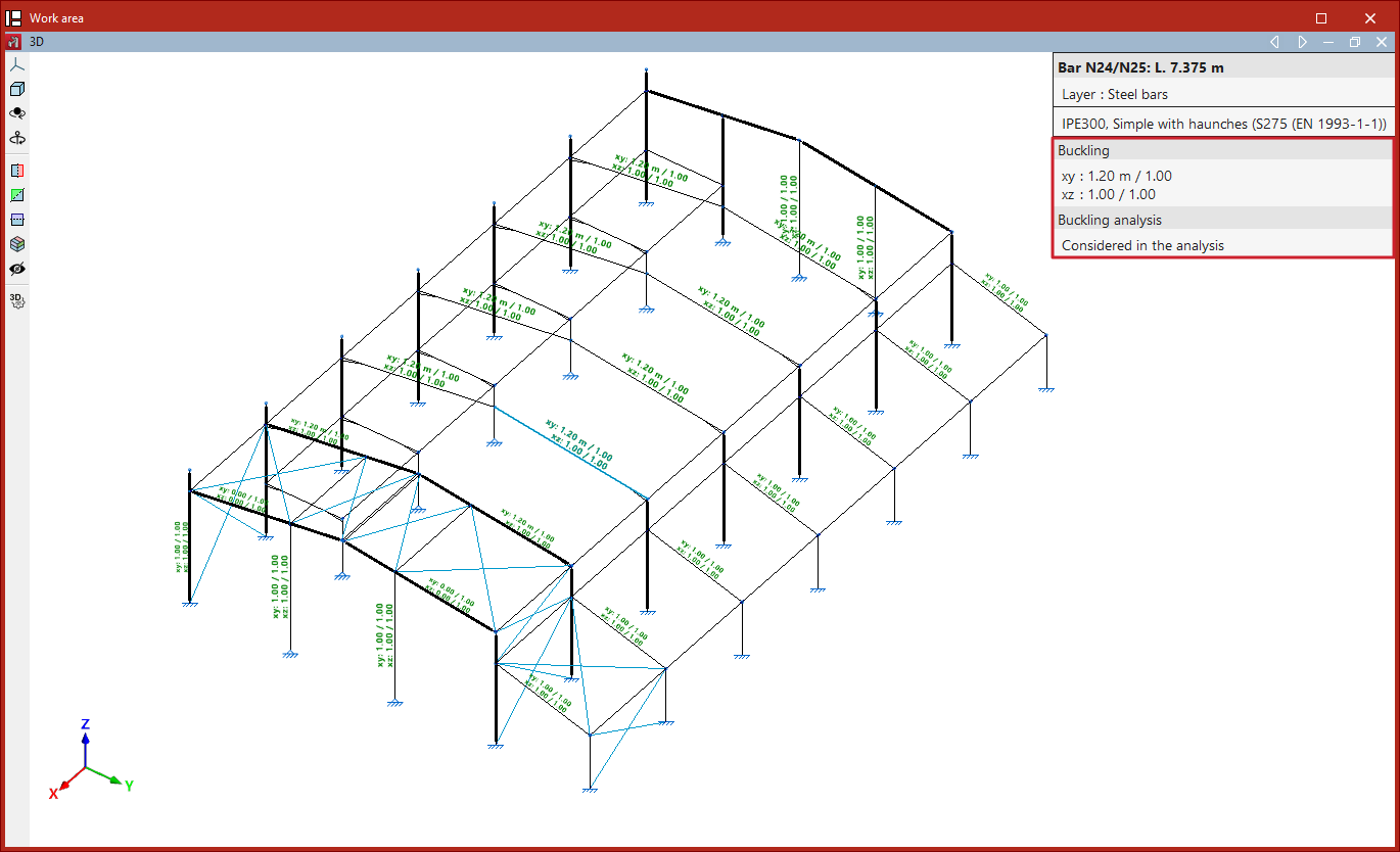
Finally, click "Accept". As you move closer to the bars, the program displays text above them showing the parameter values entered for the XY plane and the XZ plane.
This information is also displayed in the pop-up window that appears when you hover the cursor over the bars, under the "Buckling" section. Furthermore, it indicates whether the bar is "Included in the buckling analysis" or not.
If no coefficients have been assigned to the bars when clicking "Analyse", the program displays a "Warning" message to this effect. If you continue, the default values will be used.
| Note: |
|---|
| Buckling parameters have a significant impact on certain bar checks. These checks vary depending on the selected code and can be viewed in the "U.L.S Checks" lists under the "Analysis" tab. Examples include the "Compression resistance" and "Combined bending and axial resistance" checks. |