Defining deflection groups and limiting deflection for bars
You can create and edit deflection groups, as well as define the limiting deflection of the beams, using the options in the "Deflection groups" menu, which is available in the "Beams" section of the top toolbar, within the "Properties" tab (under the "Structure" sub-tab).

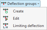
They are as follows:
- Create
- Edit
- Limiting deflection
Creating deflection groups
First, click on the "Create" option to create deflection groups.
A deflection group is a set of aligned bars that are considered together when calculating deflection, even if there are intermediate nodes.
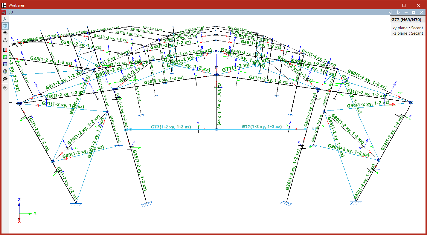
When this option is selected, the program displays text above the bars indicating the deflection group to which they belong and, in brackets, the type of deflection in each of the two local planes of the section. By default, each bar is a single secant deflection group.
If desired, you can group several aligned bars together to calculate their deflection as a single unit. To do this, left-click on the start node and then on the end node of the group of aligned bars.
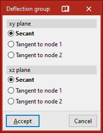
This opens the "Deflection group" window, where you can select the deflection type for each of the two local XY and XZ planes of the section.
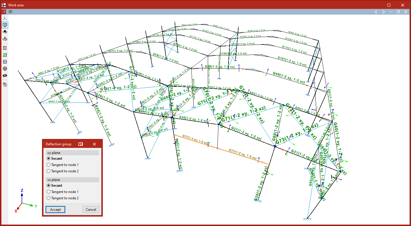
This could be "Secant", "Tangent to node 1" or "Tangent to node 2":
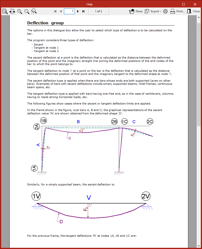
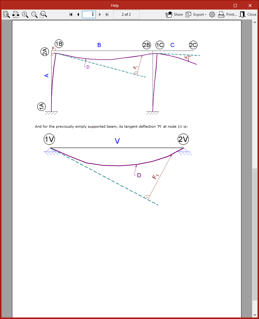
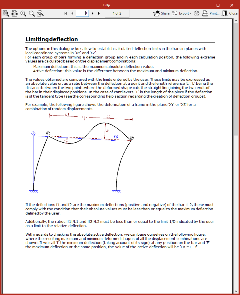
- The secant deflection is defined as the distance between the curved line and the straight line connecting its two endpoints.
- The tangent deflection, on the other hand, is the distance between the curved line and the straight line tangent to the curved line at one of its endpoints.
| Note: |
|---|
| Typically, the secant deflection is used for interior spans between columns, and the tangent deflection for cantilevers or columns with drifts. |
For more information on calculating deflection, click on the button at the top of the window’s title bar to access the program’s "Help" section.
After clicking "Accept", the program creates the deflection group between the selected nodes.
Editing deflection groups
The next menu option is "Edit", which allows you to change the deflection style of groups that have already been created.
When you hover the cursor over each deflection group, a box appears on the screen displaying the information entered. In addition, the two end nodes are identified in the model.
You can select the groups by clicking on them one by one or by using a selection window. Then, right-click.
This brings up the "Deflection group" window, where you can modify the deflection types selected for each of the section's local planes.
Defining the limiting deflection
Finally, use the "Limiting deflection" option to set the deflection limits for each group. After selecting the groups, right-click to open the settings window.
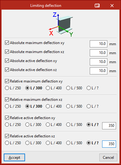
To make it easier to identify the local section planes, a diagram showing the local coordinate axes is provided at the top; these use the same colour coding as in the model.
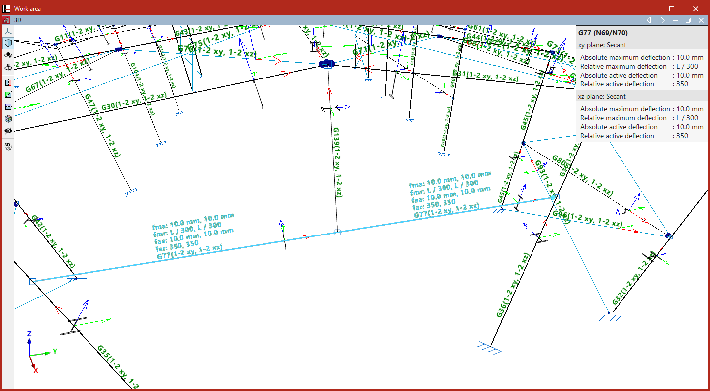
You can then tick the various boxes to apply the "Absolute maximum deflection", "Absolute active deflection", "Relative maximum deflection" and "Relative active deflection" to both planes.
Absolute deflection limits are entered in the units of measurement defined in the project, whilst relative deflection limits are specified as a specific fraction of the reference length "L".
The maximum deflection refers to the maximum deflection in the specified plane for all combinations of displacements.
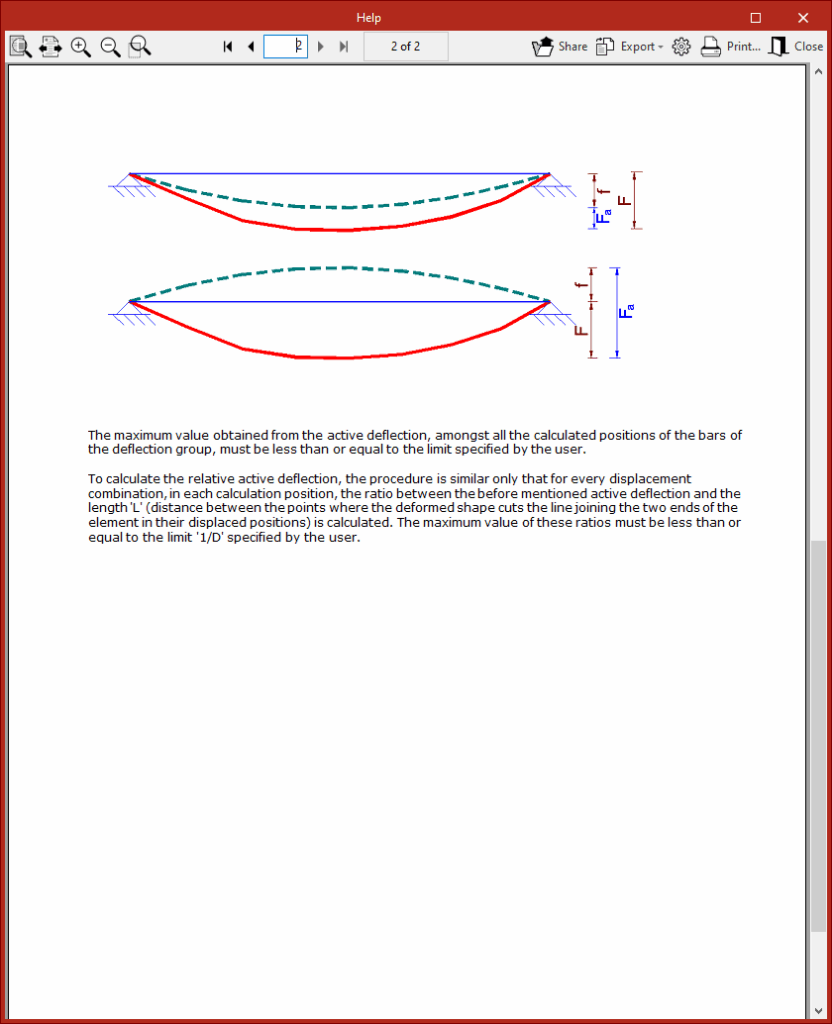
Furthermore, the active deflection is defined as the difference between the maximum and minimum deflections.
The top button on the title bar of this window allows you to access the program’s “Help” section regarding the definition and calculation of the values mentioned.
After clicking "Accept", the applied limit values will be displayed on the beams in the model and in the tooltip that appears when you hover the cursor over them.
| Note: |
|---|
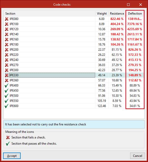
| Next, from the "Analysis" tab, you can use the "Check elements" option to verify whether the sections in the series comply with the specified limit deflection values. |